 Alpenglow Industries
-
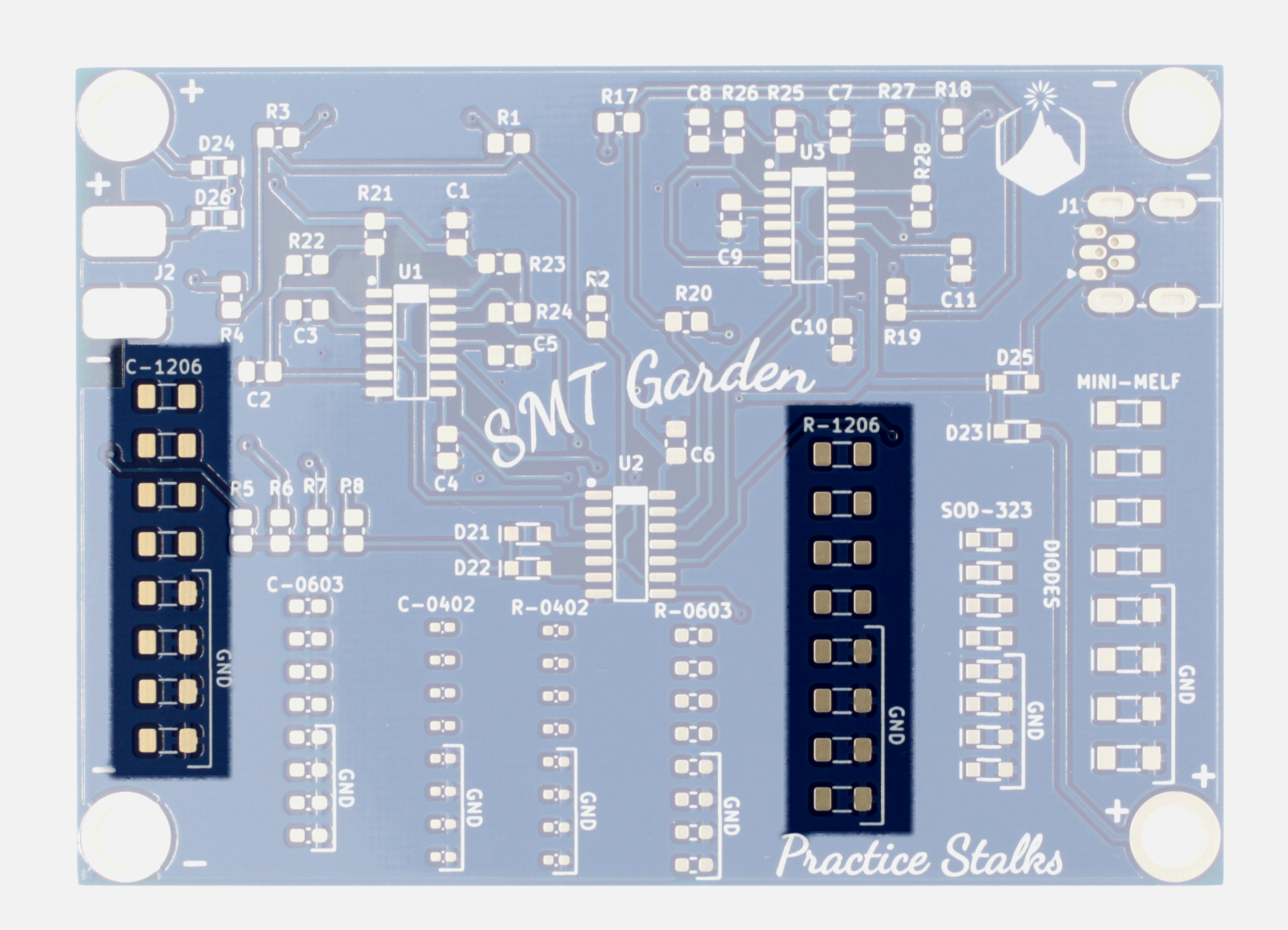
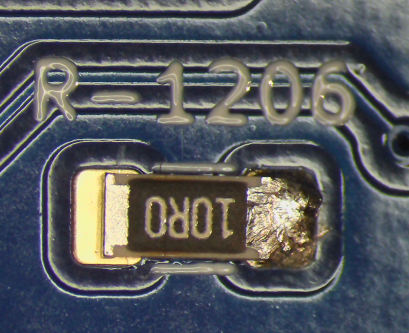
1Solder 1206 capacitor and resistor practice stalks
![]()
![]()
Gather your supplies. You'll need:
- a soldering iron (60W min) set to 700-750F (370-400C)
- a fine but not sharply pointy tip (0.8mm is good and we prefer bent tips)
- a flux pen (rosin RMA or water-soluble, most no-clean is not active enough)
- small diameter solder (0.4mm or below is best)
- tweezers (we like curved tip ones, but straight work too. They need to be very pointy to pick up small components.)
If you need a soldering iron kit with the above supplies, we sell those!
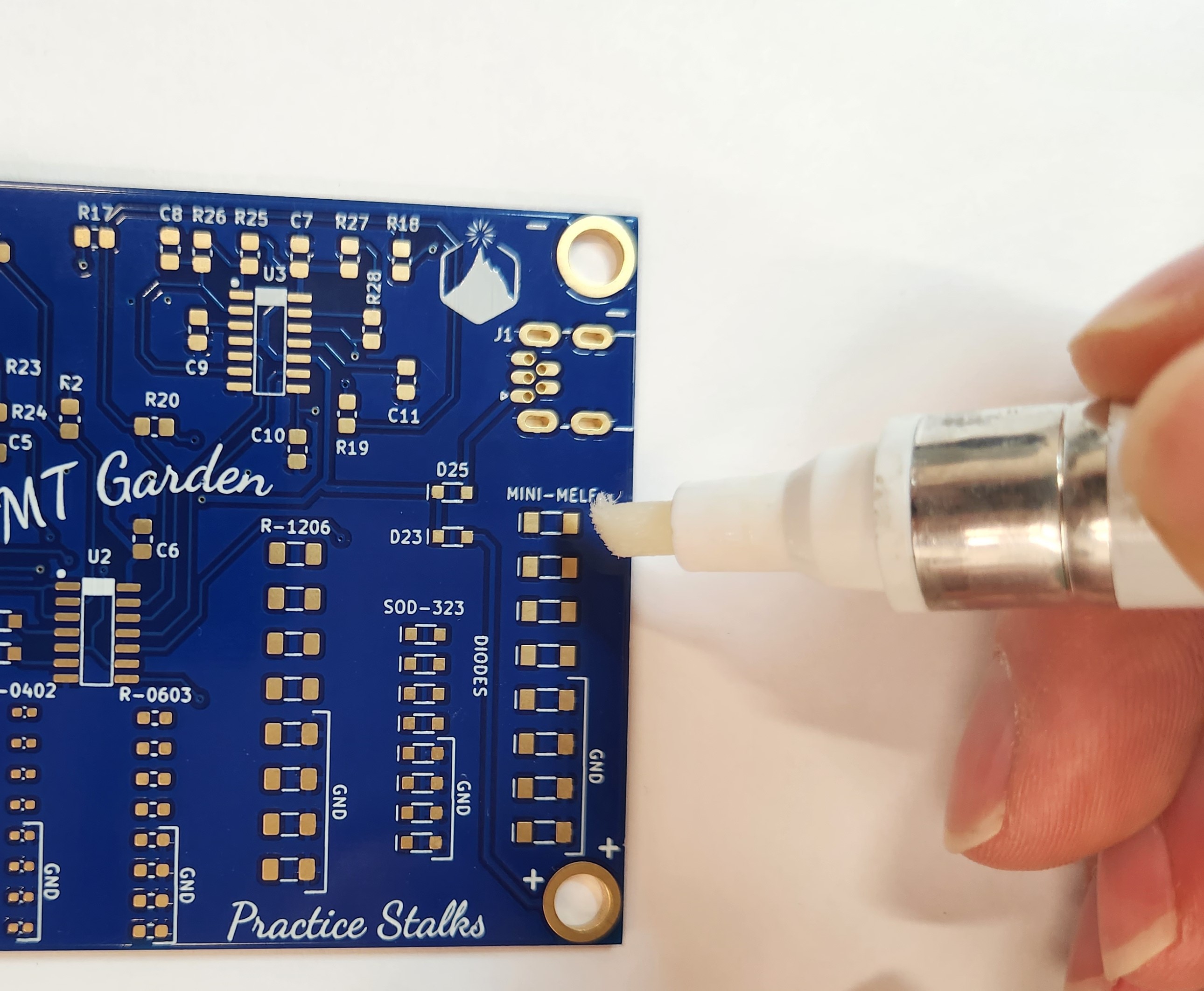
Flux is very important for surface mount soldering. You'll be using smaller diameter solder (we like 0.4mm), and it will contain less flux than typical larger-diameter solder. So the first step before you start to solder is: always coat the pads with flux.![]()
![]()
How to Use Flux:
We like using a flux pen, as it adds just enough. The type of flux is also important, most no-clean flux will dissipate way too quickly for easy surface mount work. We like using rosin RMA (rosin mildly activated) or water-soluble flux. Water soluble is the best, but you must wash it off with water after you're done. Keeping it on for days can cause the joints to corrode, and it's also mildly conductive and can wreak havoc with small analog signals. Rosin RMA flux can be easily removed with 90% isopropyl alcohol, but it's much less aggressive and is often not necessary to clean (though we think clean boards look better, probe better, and make it easier to spot problems!).
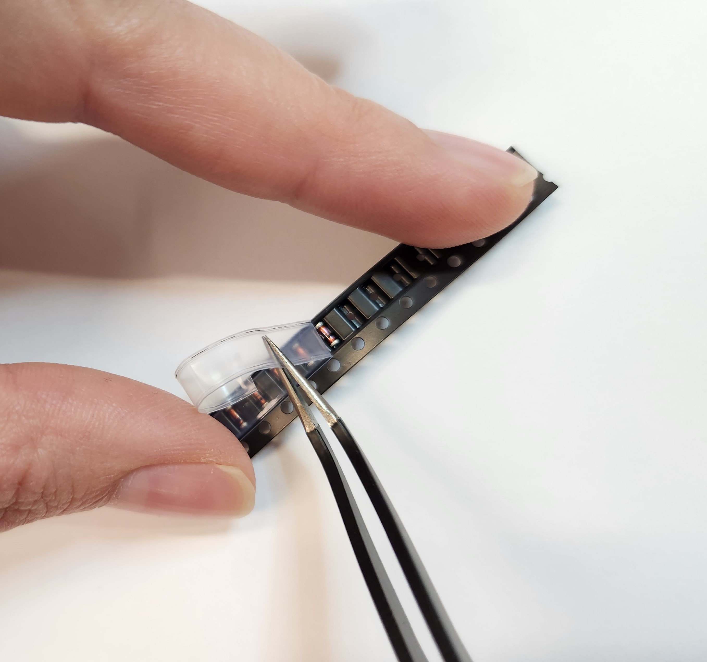
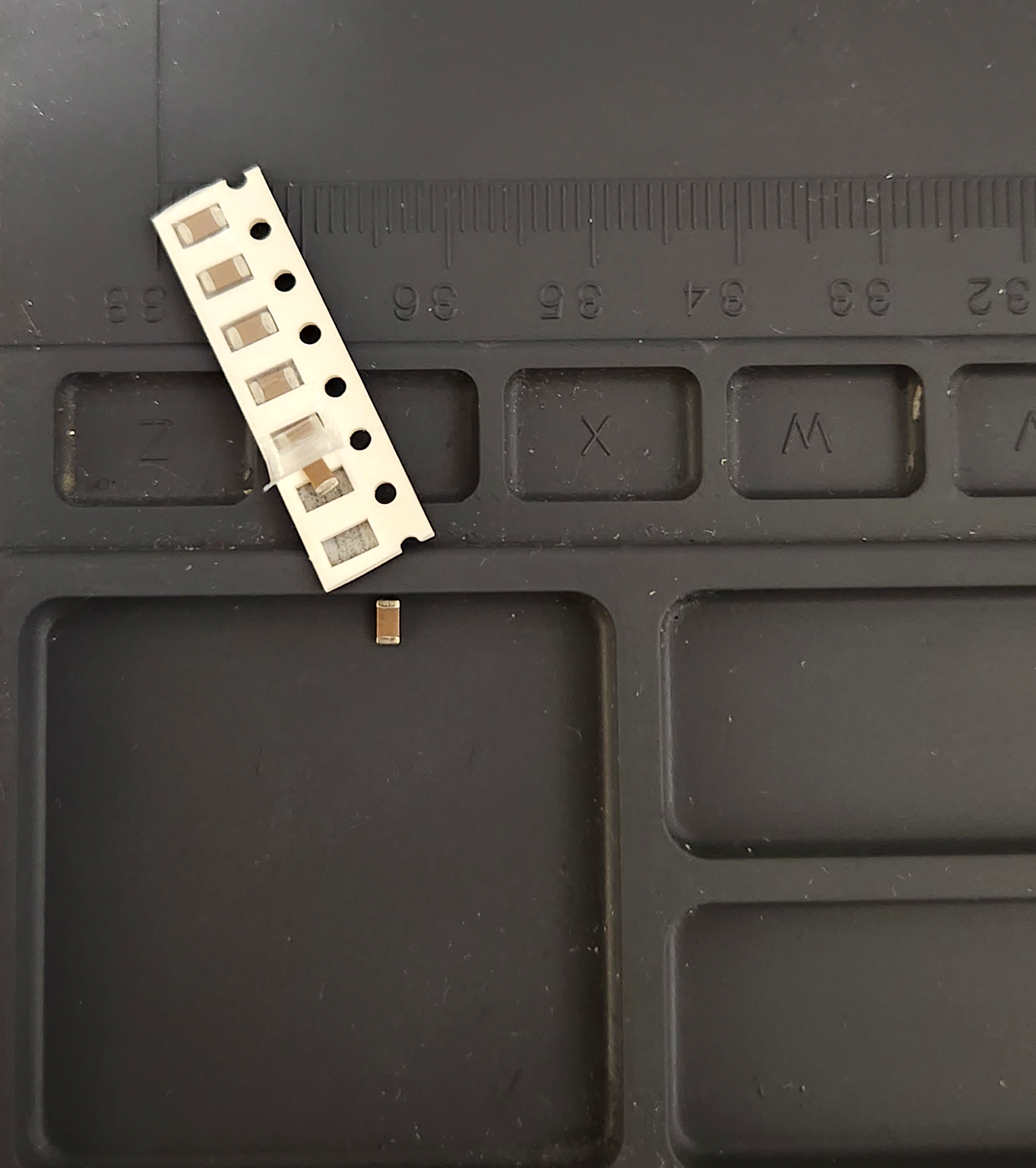
How to Remove Components from Tape:
Do this over a desk so that your components drop straight to your work surface. A soldering mat is very handy, especially the ones with small compartments molded in. Either use a fingernail, or grab your tweezers and insert under the clear tape at the end. Then slowly pull back. Your components might jump out at this point, that's OK. Turn the tape over and tap to release all components.
Note: When soldering the actual circuit, only release the number of parts needed! This helps you detect mistakes - if you find you have an extra or are one short, you may have soldered a component in the wrong place!![]()
![]()
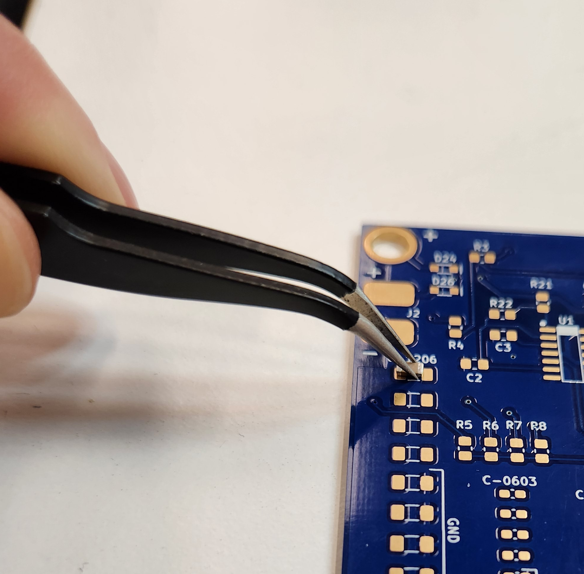
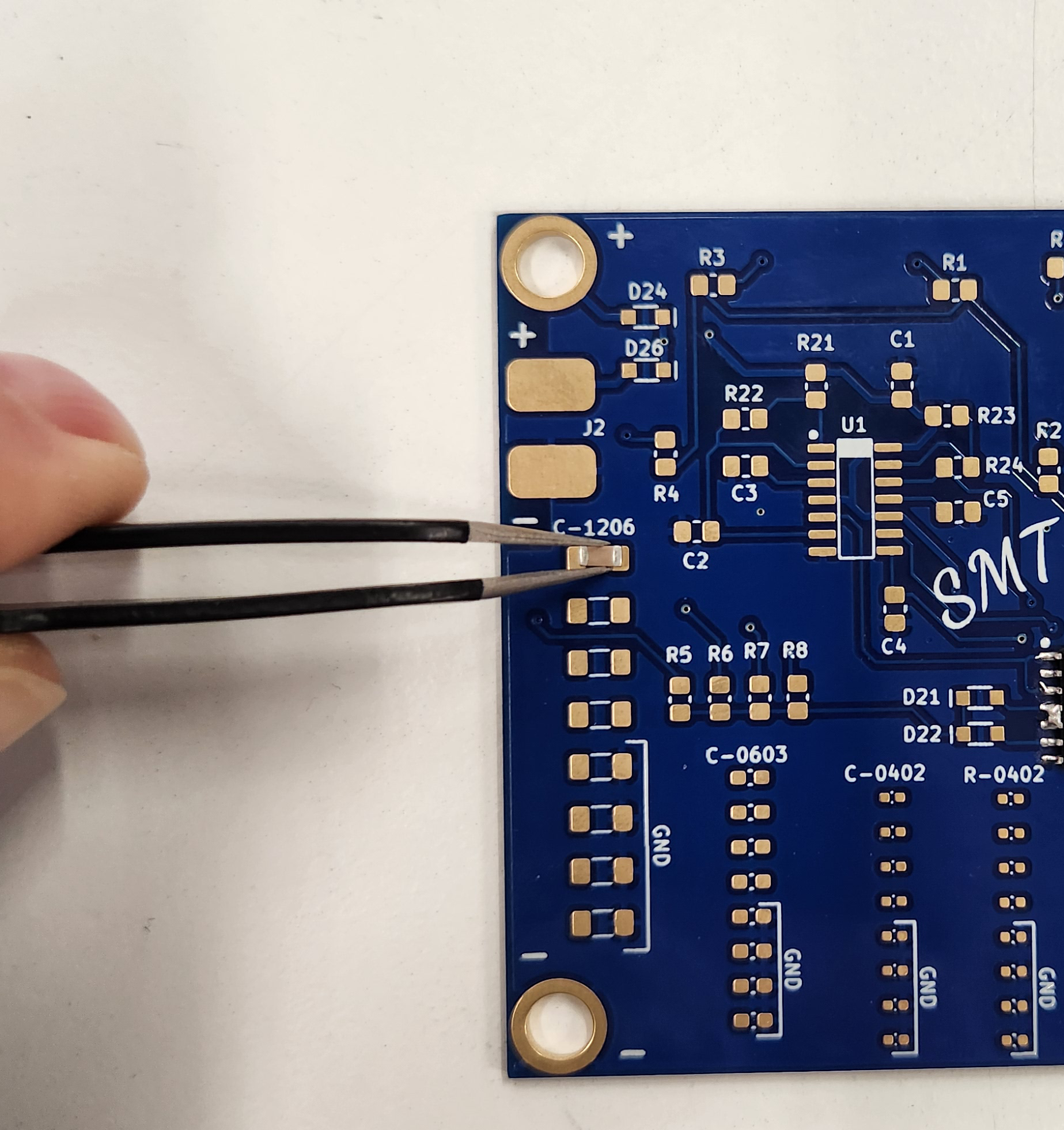
How to Hold Tweezers:
When soldering surface mount components, hold the component with tweezers in your non-dominant hand and the soldering iron in your dominant hand. Getting the hang of how much pressure to use with the tweezers takes a little practice - don't worry if you accidentally fling components across the room at first! Practice holding a component just above your table with tweezers, and gradually lighten your grip until the component falls to the table. Do this a few times to get a feel for how light your grip can be. Ideally, you want to hold a component with just enough force that it doesn't fall out of the tweezers. We like using curved-tip tweezers, you can use them with either the tips "up" or tips "down", both are shown below. Tips up can be a more stable way to hold a component, and make it easier at first to place your components flat, but it also requires a lot of component-free space around them, and may be a little less ergonomic. Eventually, you'll need to get into tight areas, so it's good to get the hang of using the tweezers tips-down.
![]()
![]()
How to SMT Solder
Technique 1 - "Tacking":
Step 1: Gently hold the component with tweezers and get a small ball of solder on the tip of your iron. Touch it to the fluxed pad (important that the pad already have flux on it!). This will create a not-so-great solder joint, but it'll suffice to hold the component in place.
Step 2: Now solder the other side normally, by holding the solder in your non-dominant hand, and touching it to the iron and the pad simultaneously. This will create a nicely flowed solder joint.
Step 3: Add flux to the first not-so-great solder joint with the flux pen. Reflow the joint with the iron. Now it should be a nice smooth solder joint![]()
How to SMT Solder
Technique 2 - "Blobbing":
Step 1: Coat one already-fluxed pad in a blob of solder. (Use one of the non-grounded pads).
Step 2: While reflowing the solder with one hand, hold the component with tweezers in the other hand and scoot it onto the pad with solder. Make sure the component is flat, and that there's enough space on the non-soldered pad for the iron tip!
Step 3: Solder the other pad normally, by holding the solder in one hand, and touching it to the iron and the pad simultaneously. This will create a nicely flowed solder joint.
Step 4: Add flux and reflow the first solder joint if needed.![]()
If you have trouble with solder joints at any time, don't always add more solder! Try just adding flux, and reflowing them with the iron.
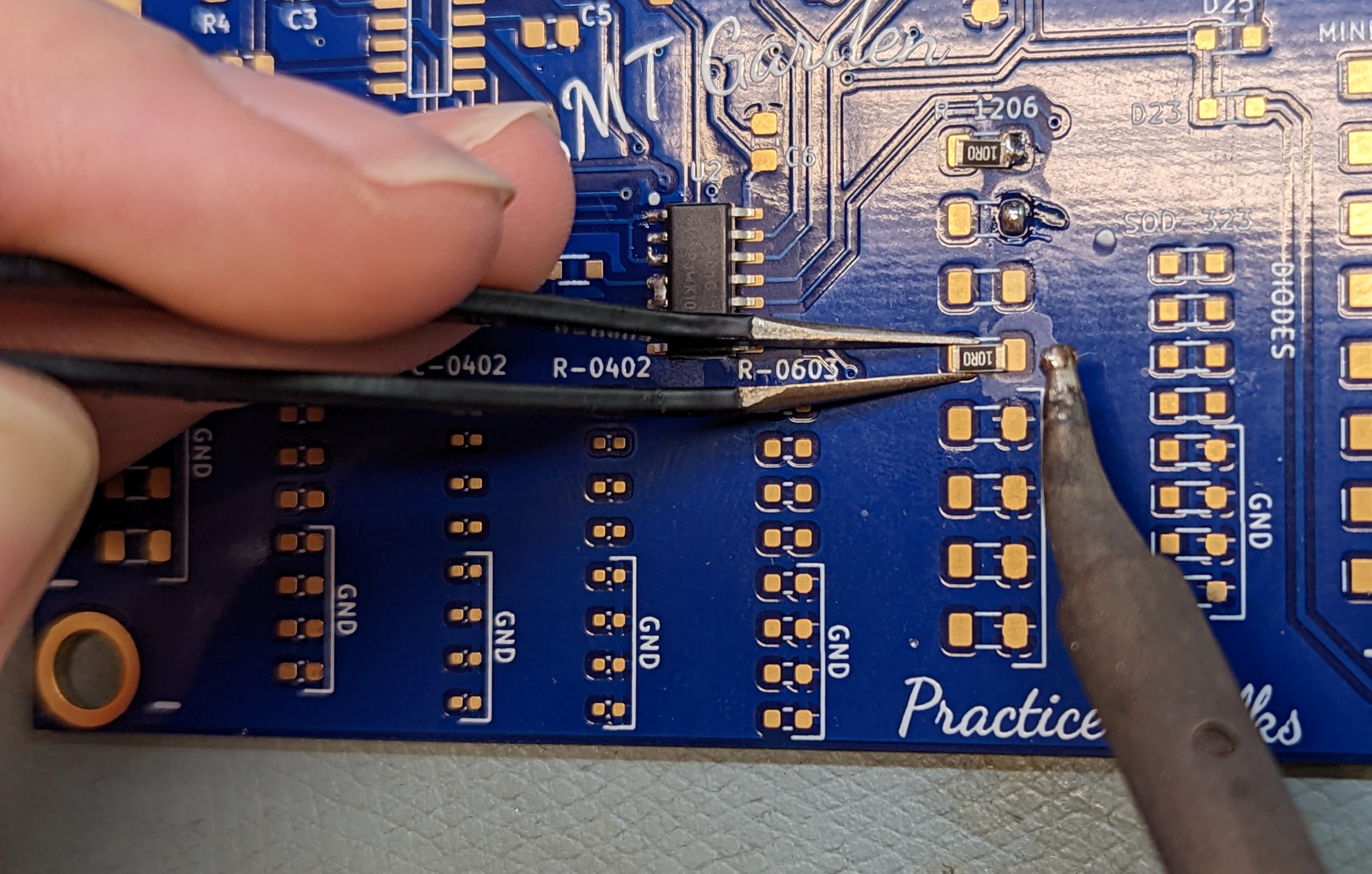
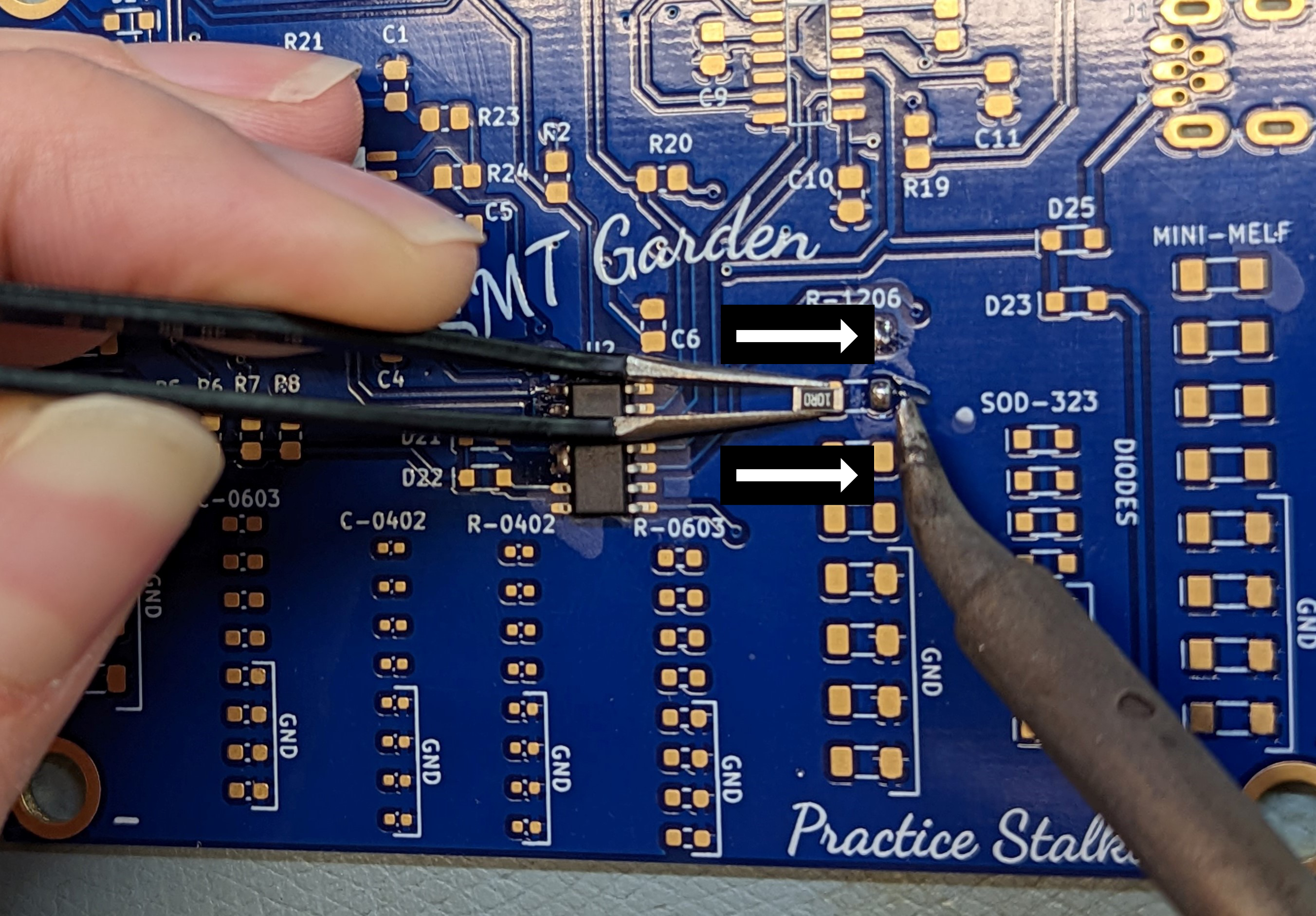
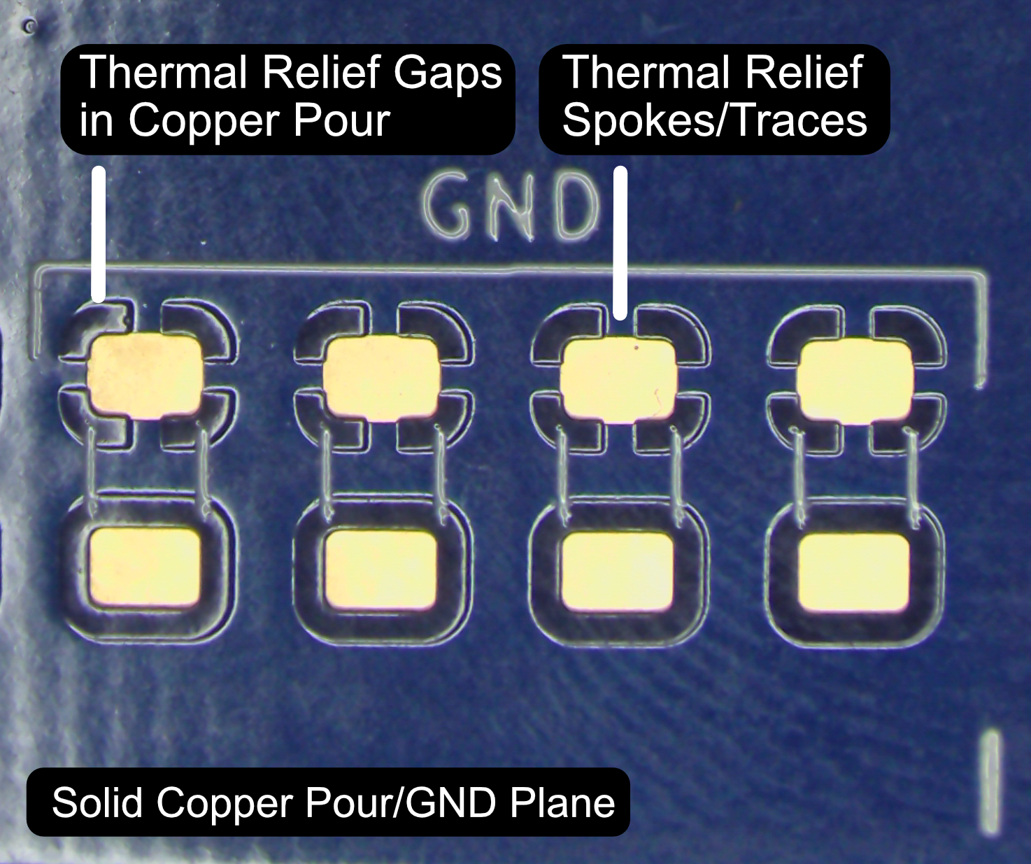
Soldering GND Pads:
You might notice that the pads attached to GND are harder to solder! That's because there's a greater volume of copper attached to these pads, which conducts the heat from the soldering iron away from them. We have used thermal reliefs on our pads, which is a gap between the solid copper pour and the pad with small traces connecting them. While these help, you'll still notice a difference when soldering. Be patient, make sure you're using the side of the tip of the iron (this is the hottest part), and make sure your tip is in good condition. Flux can also help conduct heat in that first second, as can adding more solder. Don't worry if you get more solder on these pads at first, or if these joints don't look as good. Just keep practicing!
![]()
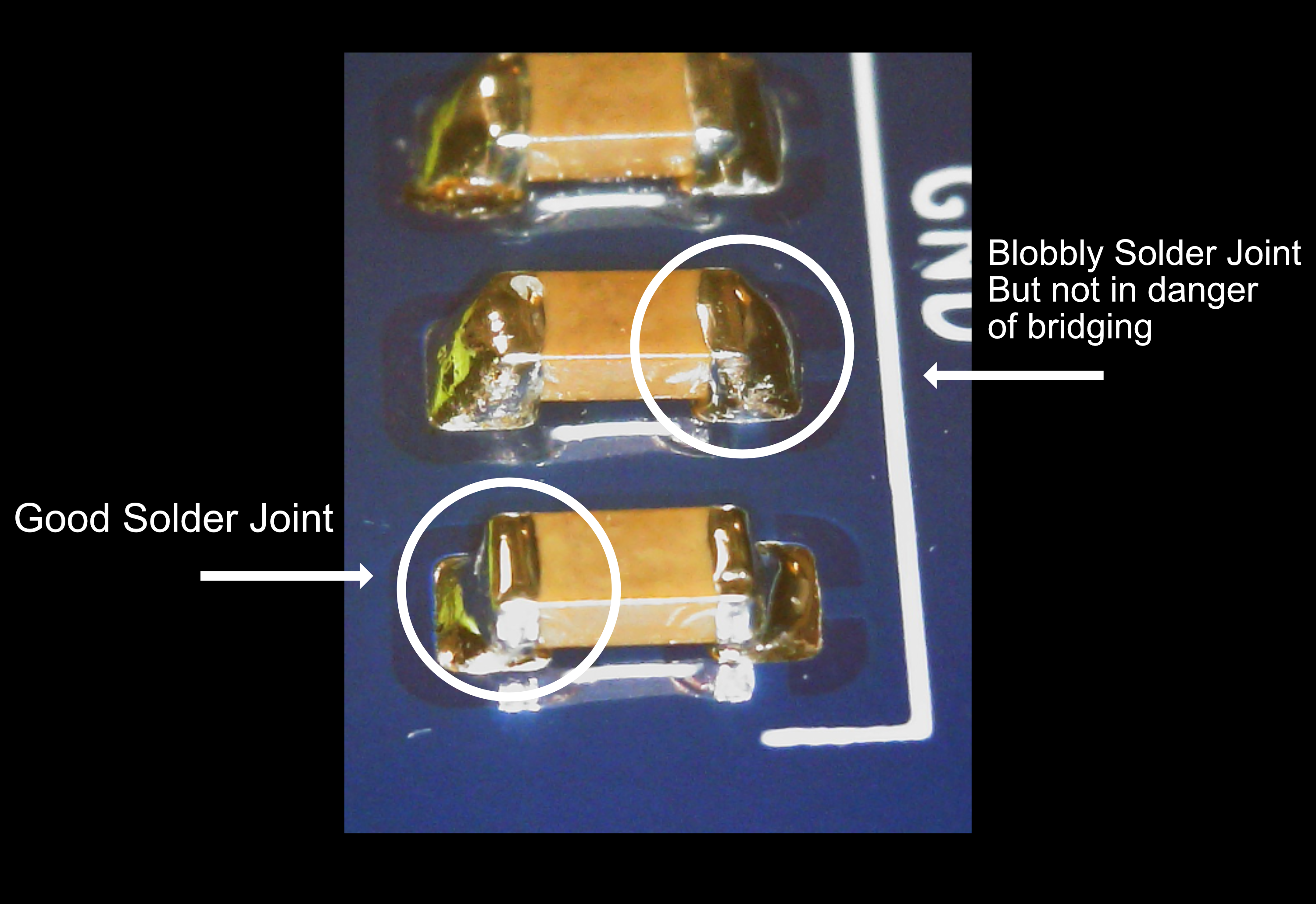
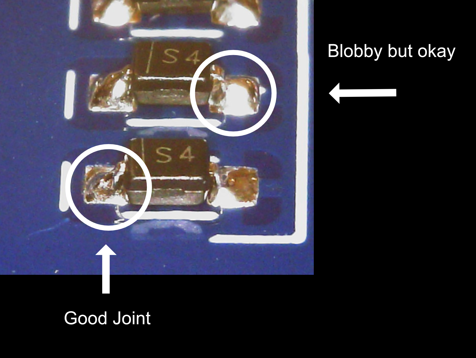
How to Identify a Good Joint:
A good joint should have just enough solder to create a nice concave "fillet" between the pad and the metallized side of the component. If yours is convex and blobbly, it's OK as long as it's not in danger of touching (or "bridging" to) a nearby component.
People make a lot of fuss about leaded solder making nicer joints. While they are shinier, lead-free solder is much more environmentally friendly, so you might as well get used to it from the start. All these examples use lead-free solder, and it's not hard to tell a good joint from a bad one. Note that it's normal for good joints to appear very shiny when the solder is still molten, and then "dull over" as it hardens.![]()
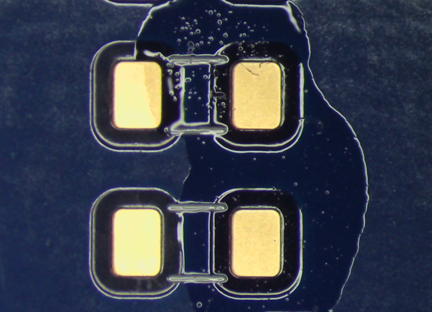
How to Identify a Bad Joint:
Bad solder joints can also be referred to as "cold" solder joints. While lack of heat can cause these, the more frequent cause of "cold" joints is lack of flux. The flux boils off very quickly when solder is heated with the iron, and oxidation causes the solder to look crystallized, like in the photo. These joints are both mechanically weaker and have higher resistance. They often will eventually fail, causing an intermittent open or flaky circuit. But do not fear, they are super easy to fix! Just add flux with a flux pen, and reflow the joint.
![]()
SMT Soldering Tips and Tricks:
- If the board is moving around too much on you, just tape it down to the table. Eventually, you'll develop enough dexterity to hold the board down with one finger on your non-dominant hand, while holding the component with the tweezers.
- If you're finding it hard to get the correct angle, don't move your hands to an awkward position, just move or rotate the circuit board!
- If your hands are shaking - do not fear, mine do too, this is normal! You can steady your hands by touching the heels of your palms to the surface of the table you're working on. This stabilizes your entire hand and allows your fingertips to do the more dexterous work of finely positioning the component and soldering iron tip.
- If you're having trouble with the solder flowing, check a few things. You can try increasing the temperature, but if you're still having trouble at 750F, it's probably not the temperature. 60W or higher irons are recommended for being able to heat up GND pads. The very tip of the iron tip is the coldest part, so if your iron tip is extremely sharp, it might not be getting hot enough. Try a wider one. Check your solder - formulations with silver (SAC - Sn/Ag/Cu) flow much better than Sn-Cu only formulations. Your tip may be oxidized - try cleaning it (when cool) with a bit of brass wool. You can use tip tinner for stubborn tips, but note it will decrease the life of the tip. Get in the habit of always putting away your tip "dirty" - meaning tinned/coated with solder. Check the type of flux, use rosin RMA or water-soluble, and add more.
-
2Solder the practice diodes and circuit diodes
![]()
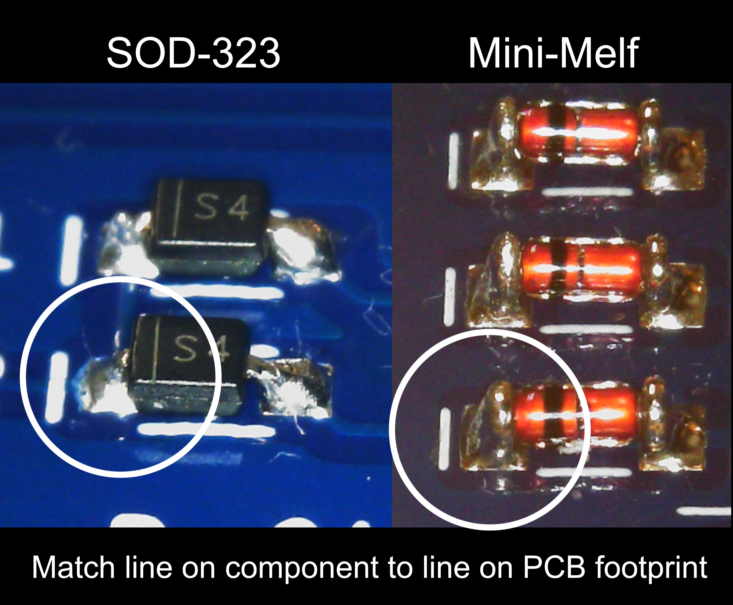
Note: Diodes are directional! be sure to match the line on the footprint to the marking on the component. The line should always denote the cathode.
Use the same techniques described above to solder the diodes, and all subsequent components. We've provided two styles of diodes - the orange glass ones are mini-melf packages, and the black ones with legs are SOD-323 packages. Other styles with flat or J leads exist too.
After soldering the SOD-323 diodes to the practice stalk, you can solder the ones that are part of the circuit (D21-D26 shown above).![]()
![]()
-
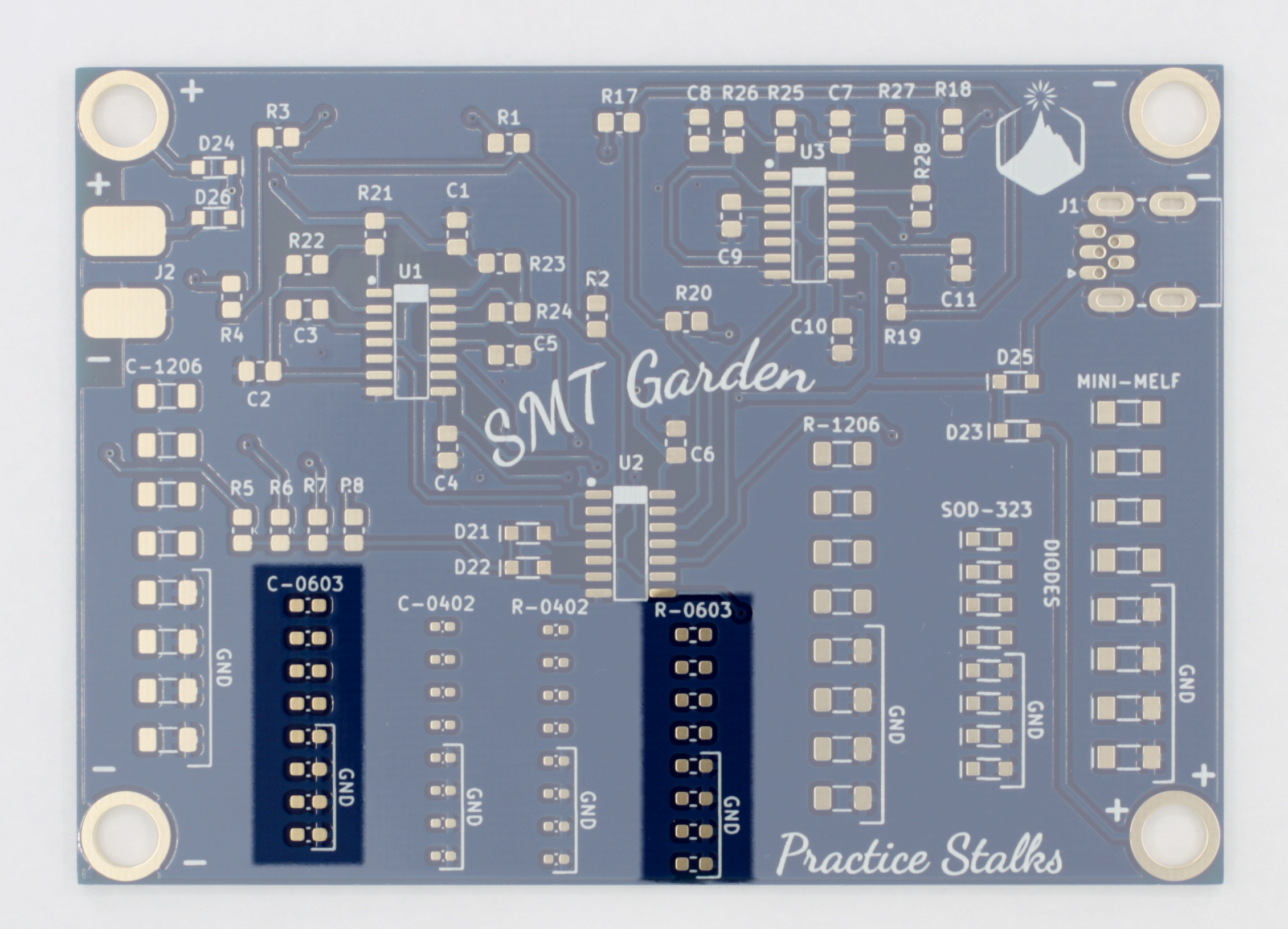
3Solder 0603 capacitor and resistor practice stalks
Now that you've aced 1206's and diodes, let's jump to smaller 0603 footprints. These you will likely want magnification for. Even if you can see them well enough with your bare eyes to solder, you'll still want magnification to fully inspect your joints! Several different tools can be used: a magnifying glass or magnifying ring light, magnifying head-mounted glasses, or a stereo microscope. It is more difficult to solder well under a USB camera microscope or a monocular microscope because you lose all depth perception.
Soldering these is the same process as the above, they're just smaller components. You might fling them across the room with your tweezers more, practice that just-enough pressure holding. If you don't have magnification, you can always save these for later and jump to soldering the chips (aka ICs) and the 0805s in the actual circuit. The 1206s and 0805s are good enough practice to start!![]()
-
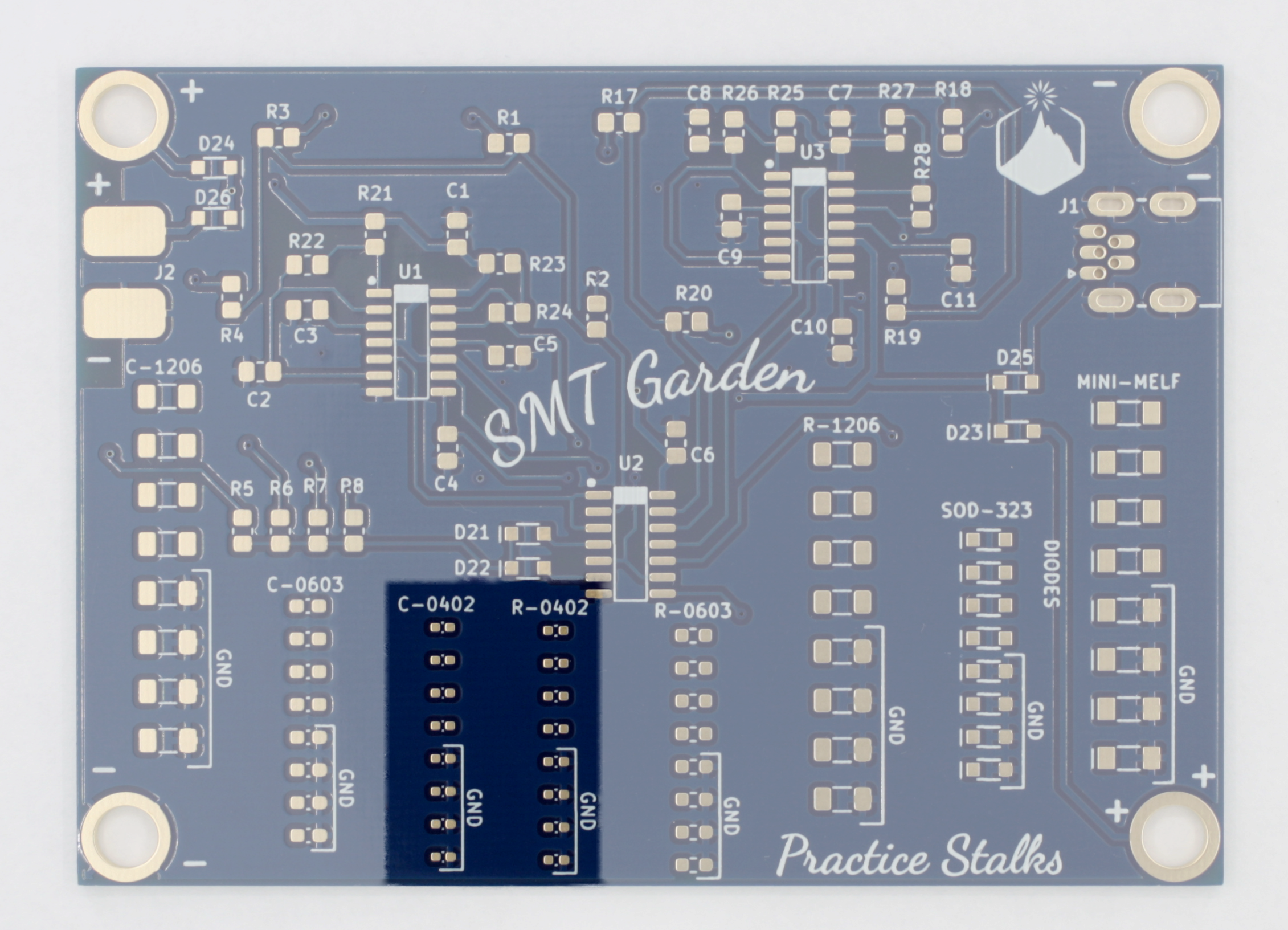
4If you're feeling confident move on to the 0402 practice stalks
If you're up for a harder challenge than 0603s, try the 0402s. These are definitely advanced, and a 90W iron with a very pointy tip, water-soluble flux, 0.3mm solder with water-soluble flux core, and a stereo microscope are all recommended. What I'm saying is don't feel bad if you find these to be extremely difficult or impossible. You can always come back to these after a few months of SMT practice on other boards!
![]()
-
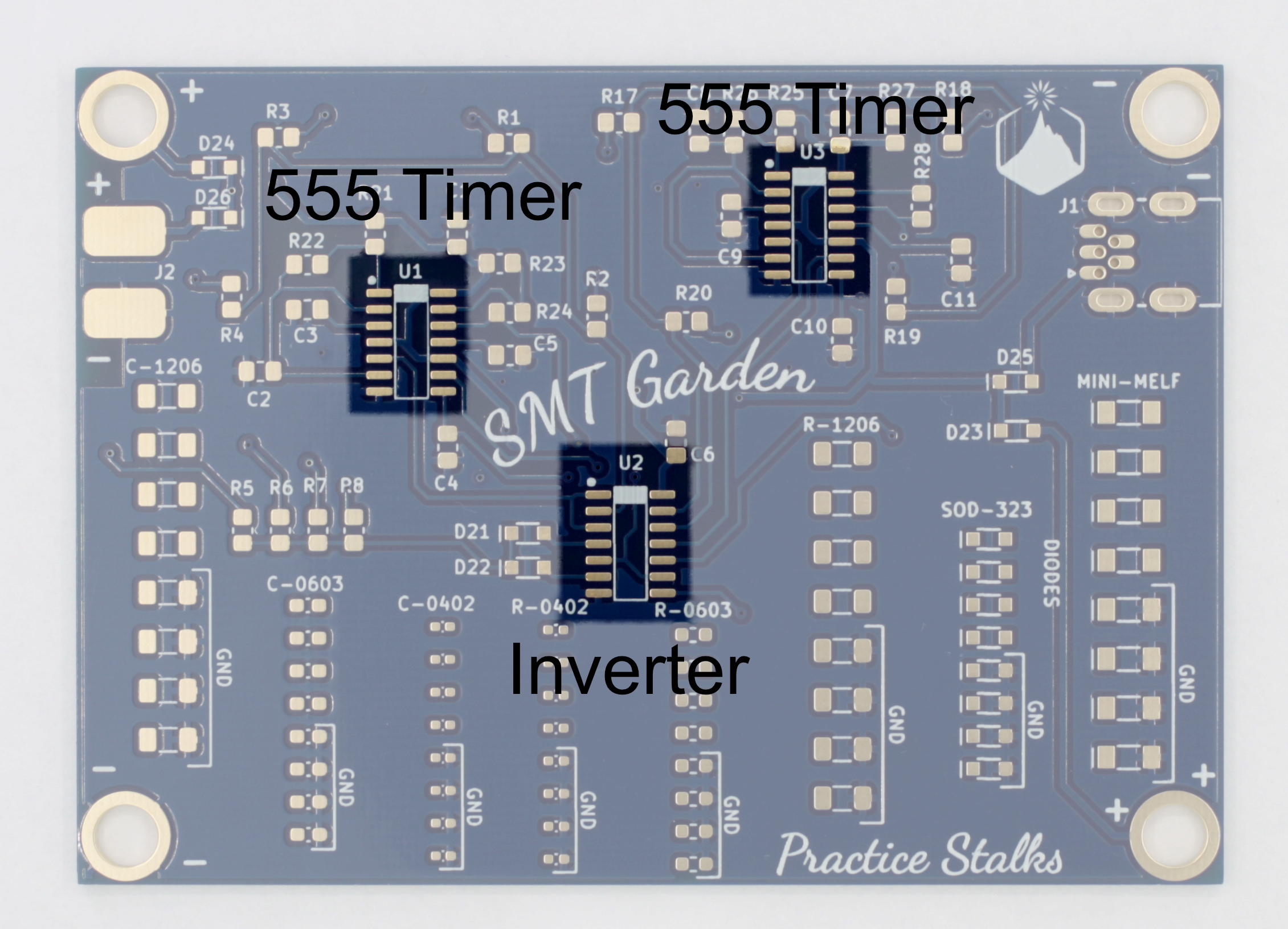
5Solder the Chips - Dual 555 timers and Inverter
Now you're ready to solder the actual circuit! These components are generically known as "chips" or "ICs" which stands for "integrated circuits." It's just a generic name that indicates a component is made up of many many subcomponents, and performs a more complex task (or set of tasks). ICs come in many flavors, there are: microprocessors, voltage regulators, timers, digital logic, sensors, and many more! The ICs on this board are two dual 555 timers (aka 556) and a hex (6-input) inverter.
Dual 555 timers (556 chips) (U1, U3)
Inverter (U2)![]()
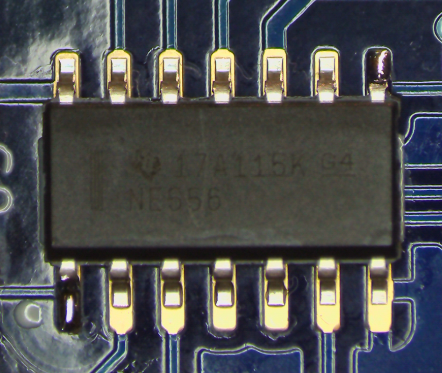
These components are directional! When soldering chips or components with multiple legs, start with fluxing the pads. Then tack down pin 1 and the diagonally opposite corner pin. To find pin 1 look for the silkscreen dot on the top corner of the footprint, match that dot to the dot or line on the component. After the 2 pins have been tacked down go through and solder the remaining pins, then go back and add flux and reflow the first two solder joints.
![]()
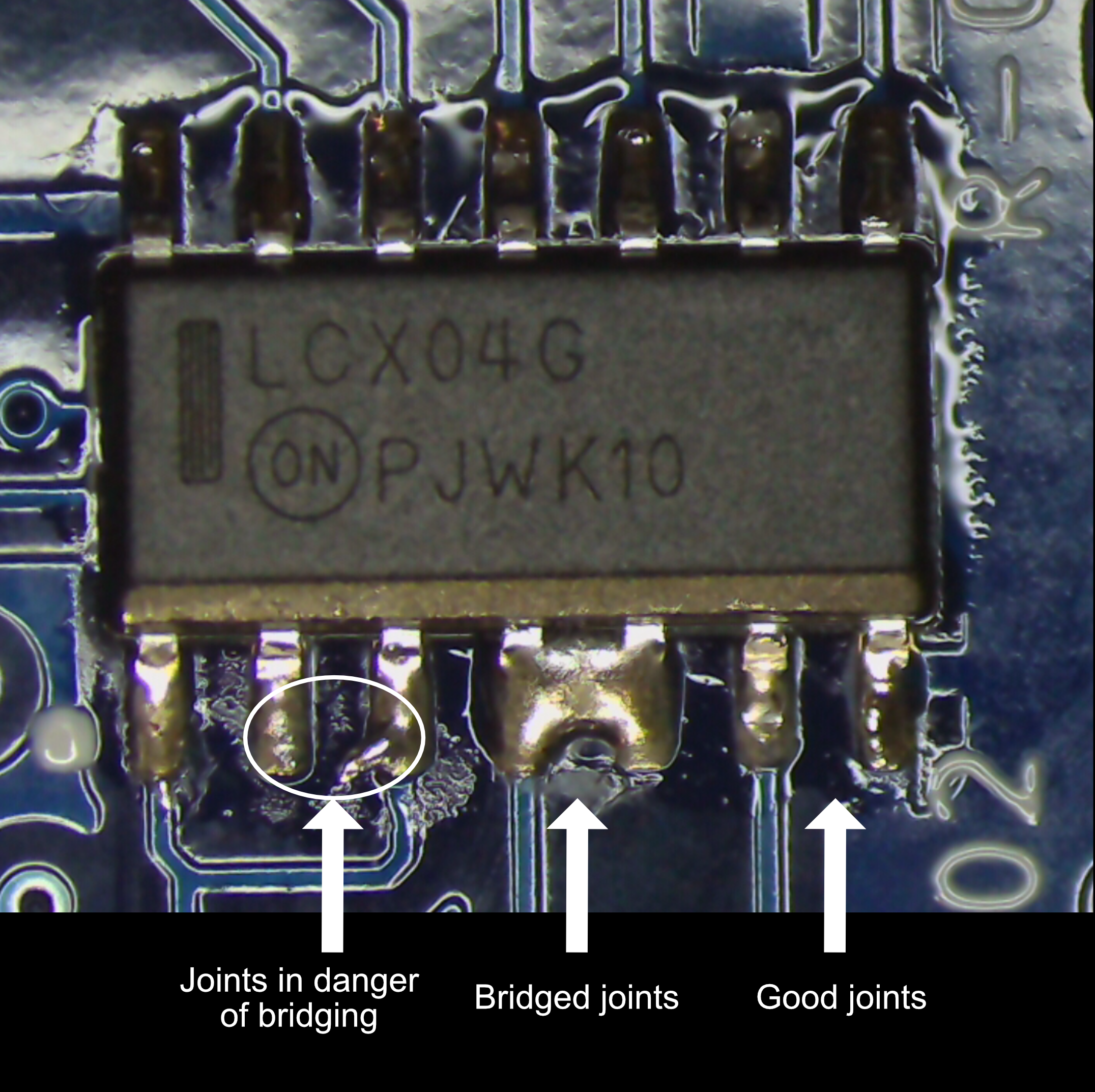
Here are some examples of good and bad soldering on an inverter chip:
![]()
-
6Solder 0805 capacitors
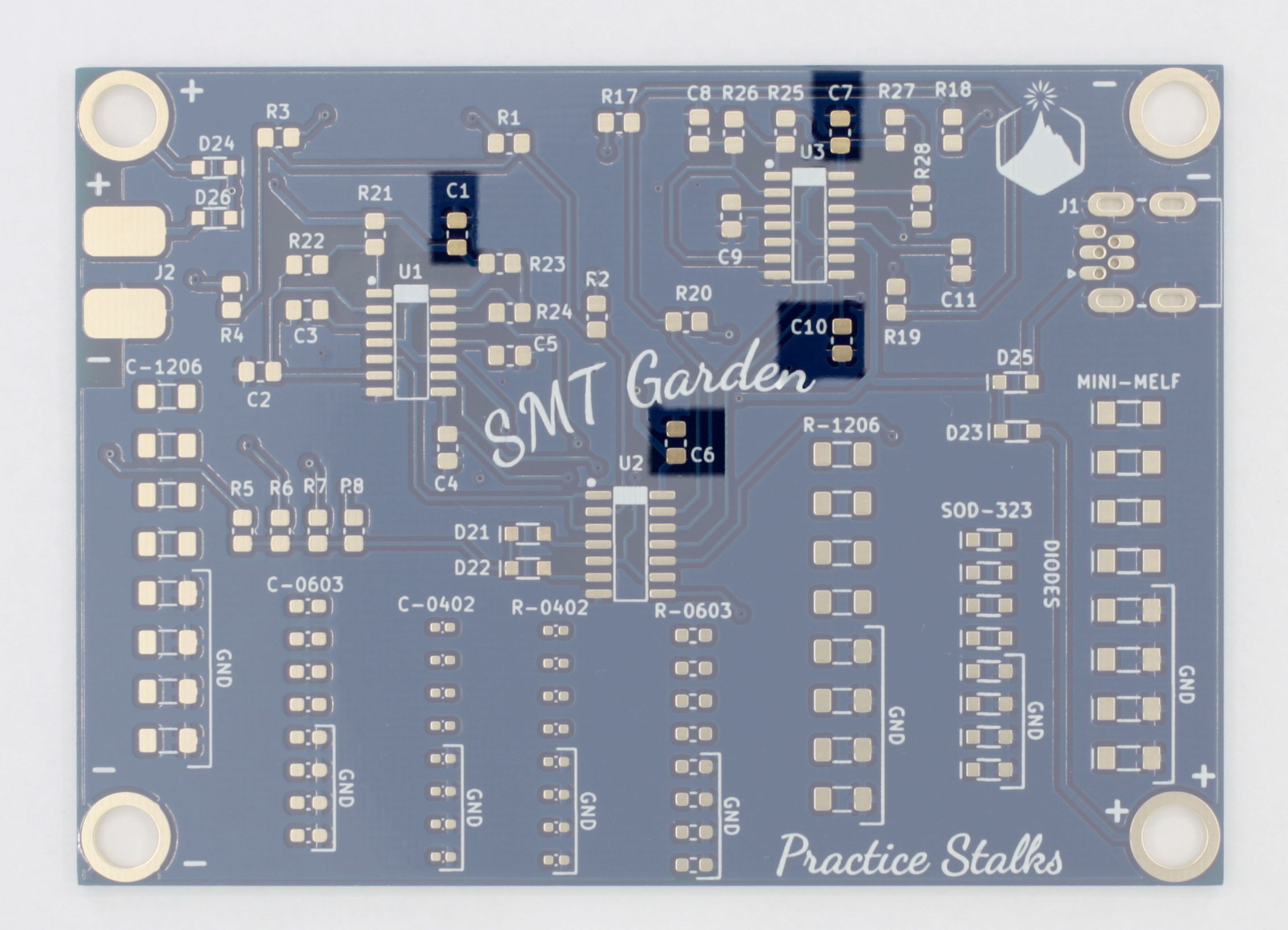
The SMT Garden uses a few different values of capacitors, all in the 0805 package. And surface mount capacitors of different values all look alike! That makes them very easy to mix up if you have several values out on the bench. We find it best to only take one component value out at a time, and only release the amount you need from the tape strip. That ensures that no extras will get mixed up with any subsequent values you solder.
0.1uF capacitors (C1, C6, C7, C10)
![]()
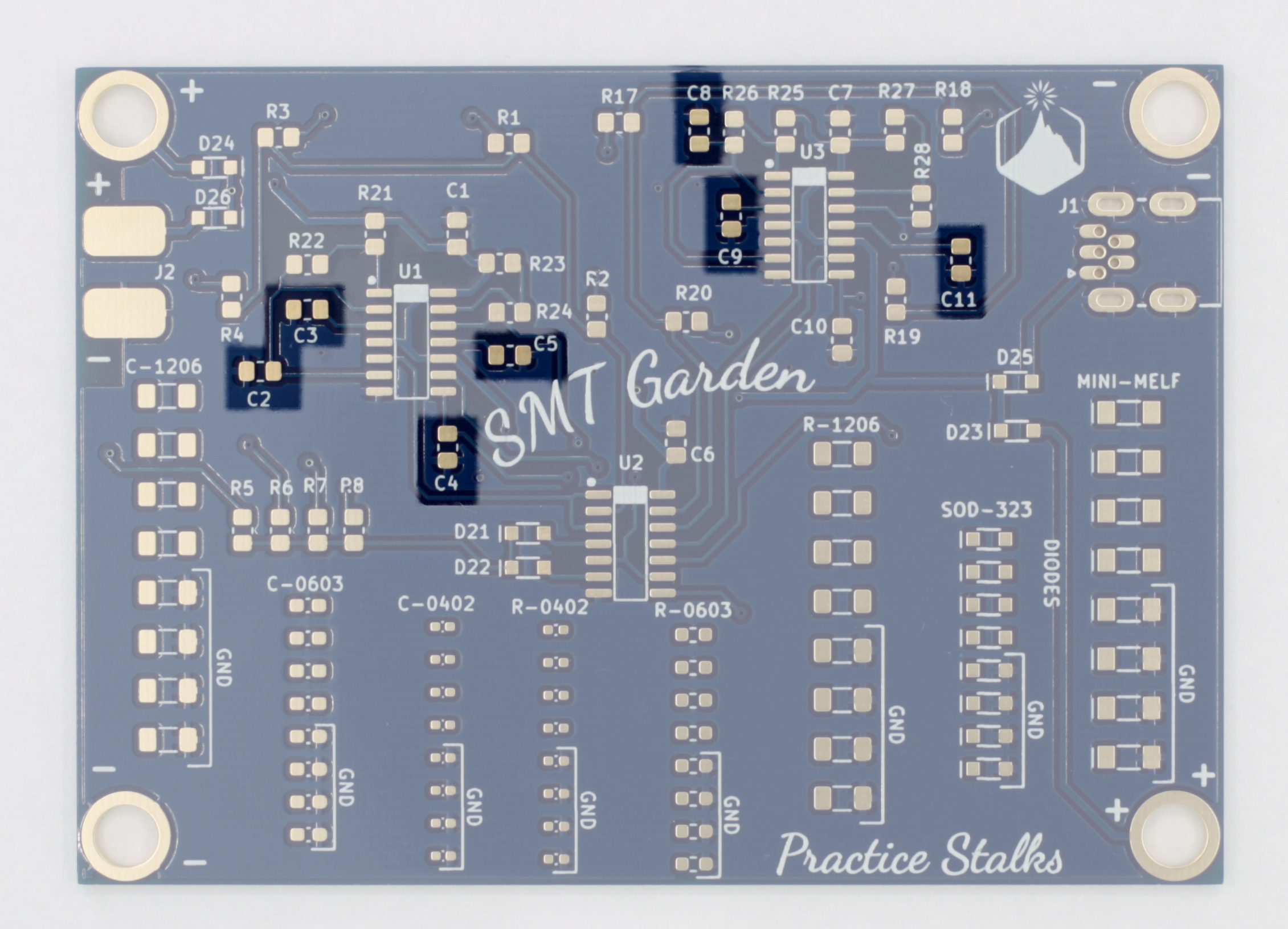
0.01uF capacitors (C2-C5, C8, C9, C11)
![]()
-
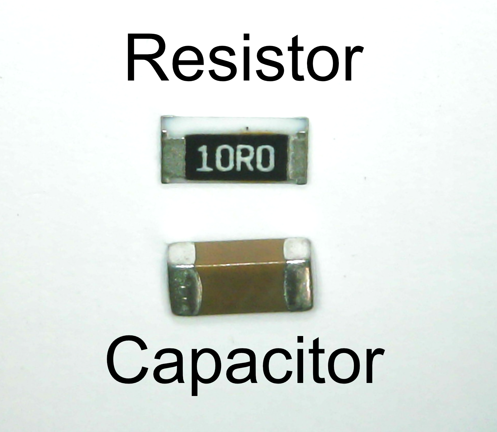
7Solder 0805 resistors
Resistors will often have their values marked on top of them with a 3 or 4-digit code. 4R7 means 4.7 ohms. 473 means 47X10^3, or 47 with 3 zeros after it, or 47,000 ohms, or 47k ohms.
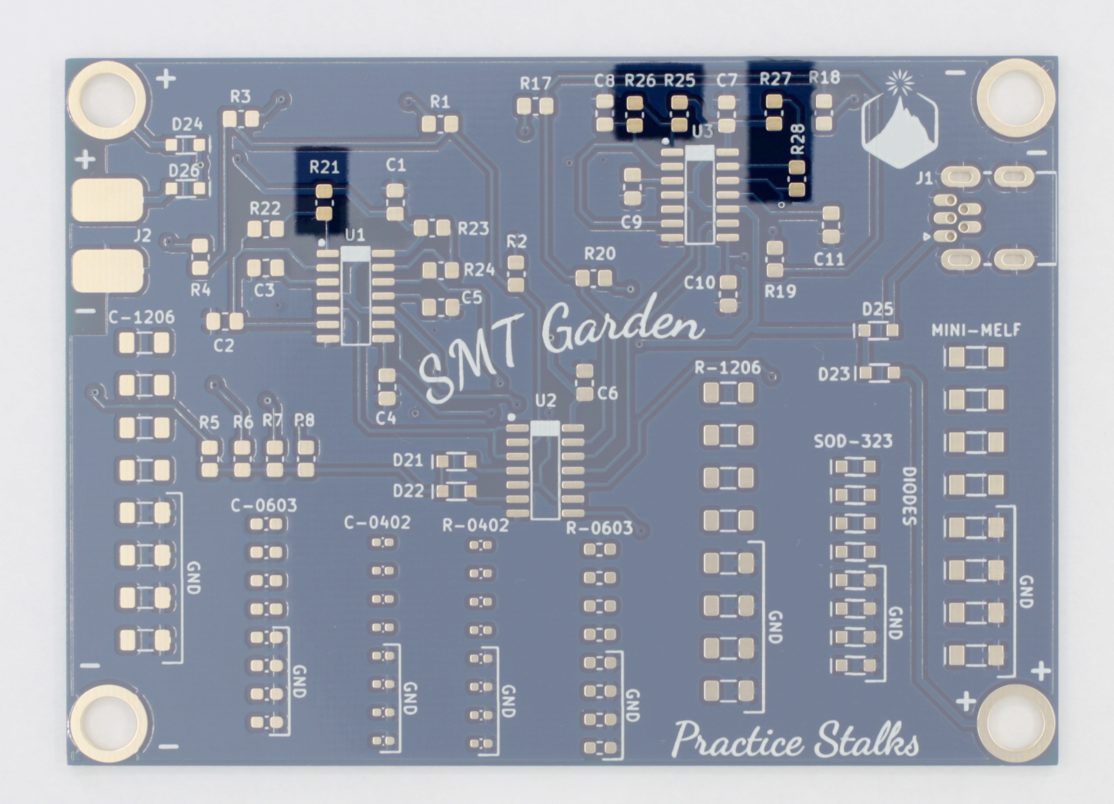
10M resistors (R21, R25 - R28)
![]()
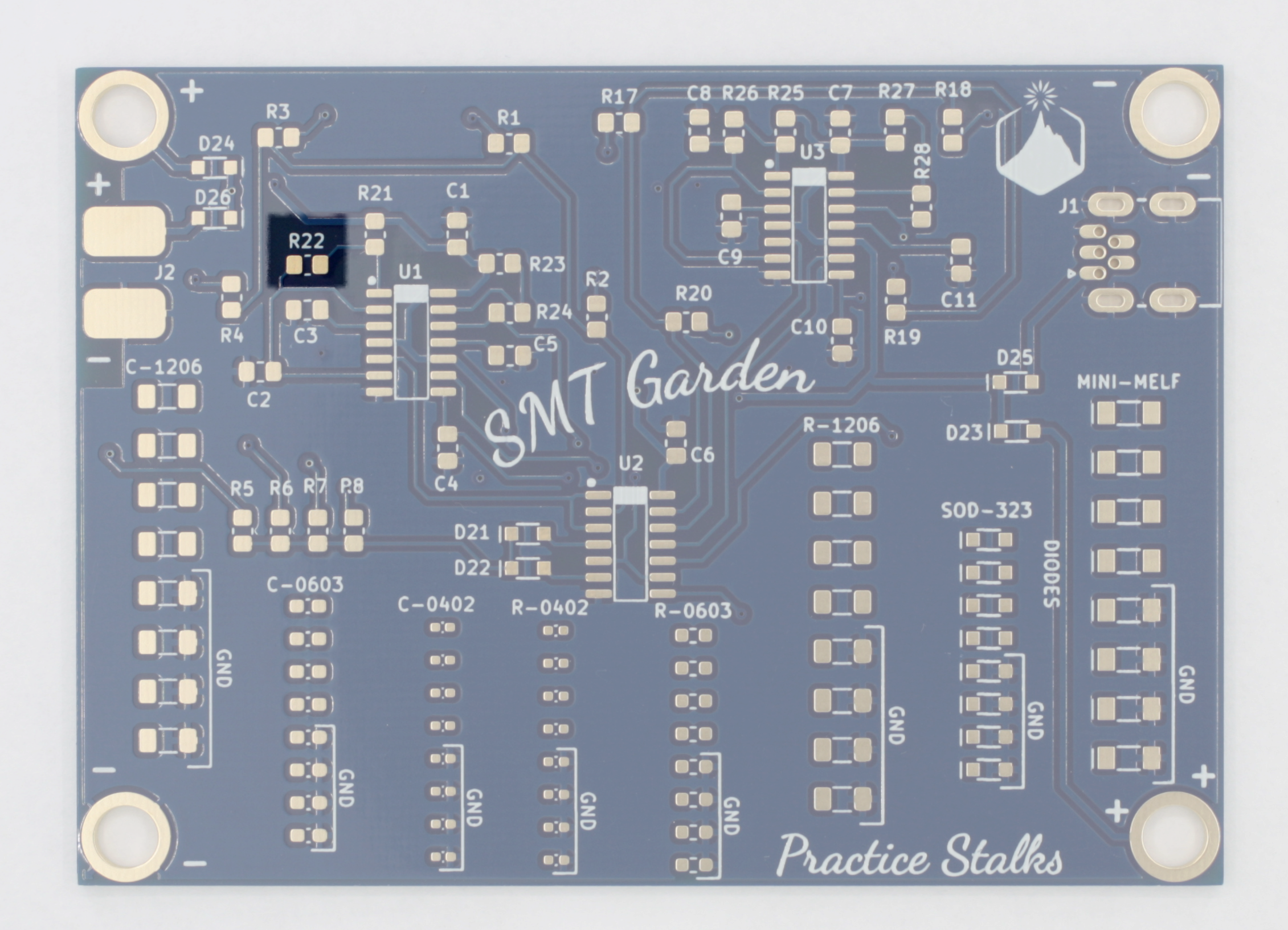
2.2M resistor (R22)
![]()
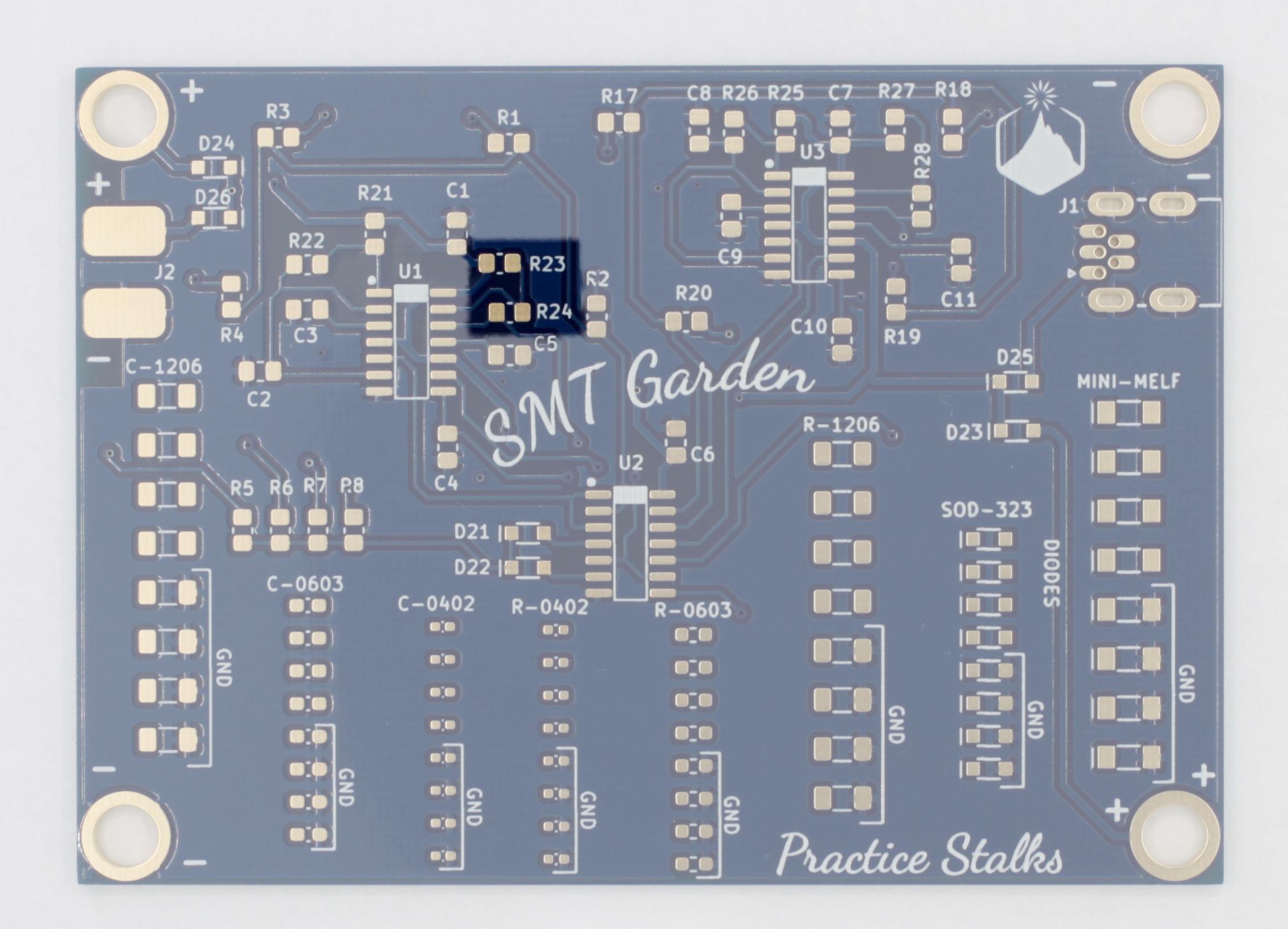
4.7M resistors (R23, R24)
![]()
-
8Solder LED resistors to the back of the board
Resistor numbers match up with LED numbers, so R17 is the resistor that feeds D17. We've made it easy for you and are using the same value of resistor for all LEDs, so you don't have to worry about mixing them up and your LEDs being much different in brightness. They're all pretty bright! After soldering, all the LEDs in each flower will blink simultaneously, but each flower will blink at a different rate! You can make each flower a different color, or each flower multiple colors. Get creative!
Note that half the resistors for the LEDs are on the back of the board, and half are on the front (you'll solder those soon).
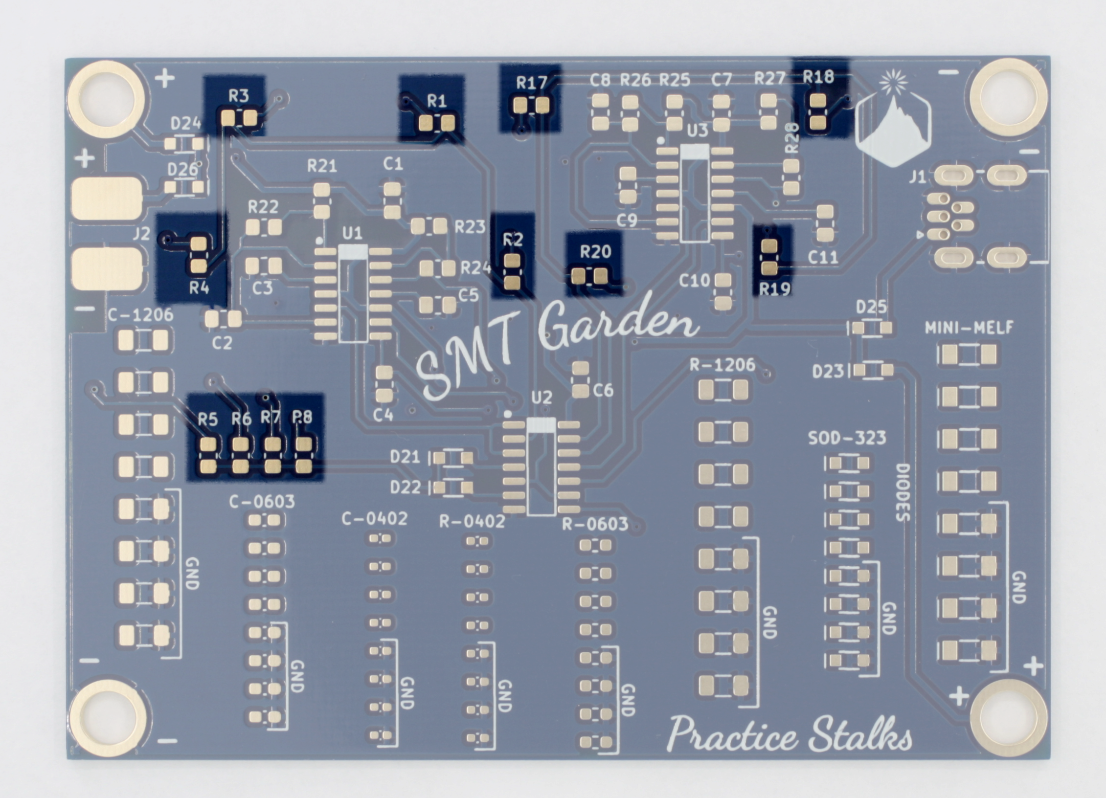
0805 resistors 1k ohm (R1-R8, R17-R20)
![]()
-
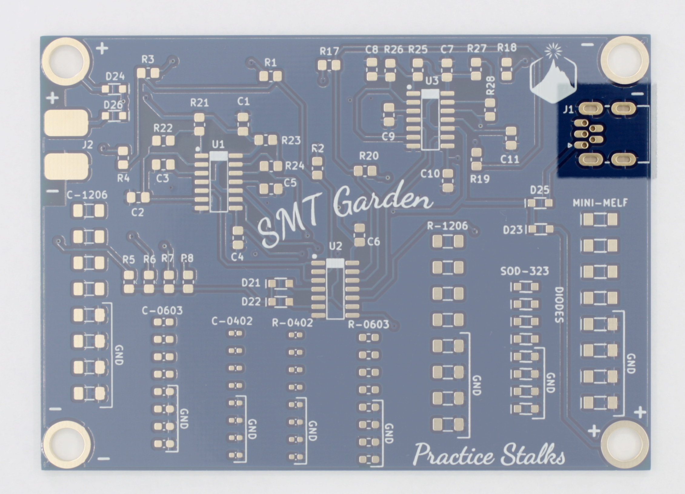
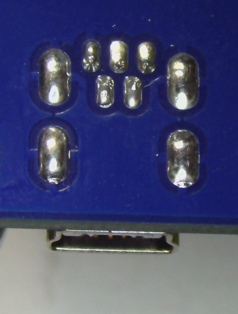
9Solder USB Connector
The USB connector is a nice through-hole connector. Even though it has tiny legs, you should have no problem with it with your new surface mount skills! We've also extended the pads in opposite directions to give you plenty of space for the iron tip. Coat all pads with flux first, and solder two of the 5 main pins to tack it in place. Then solder the larger mounting pins (these are connected to the shell of the connector - don't try to hold the connector in place while soldering these, otherwise you will get burned!). Then solder all remaining pins and go over anything that needs to be reflowed with a little flux and the iron tip. If you accidentally bridge solder between the pins, use solder wick to remove it.
![]()
![]()
-
10Add magnetic standoffs to each corner
This will raise the PCB off the table and make soldering the top of the PCB much easier. Just sandwich the board between the screw and the standoff, and tighten the screws with a Phillips screwdriver.
![]()
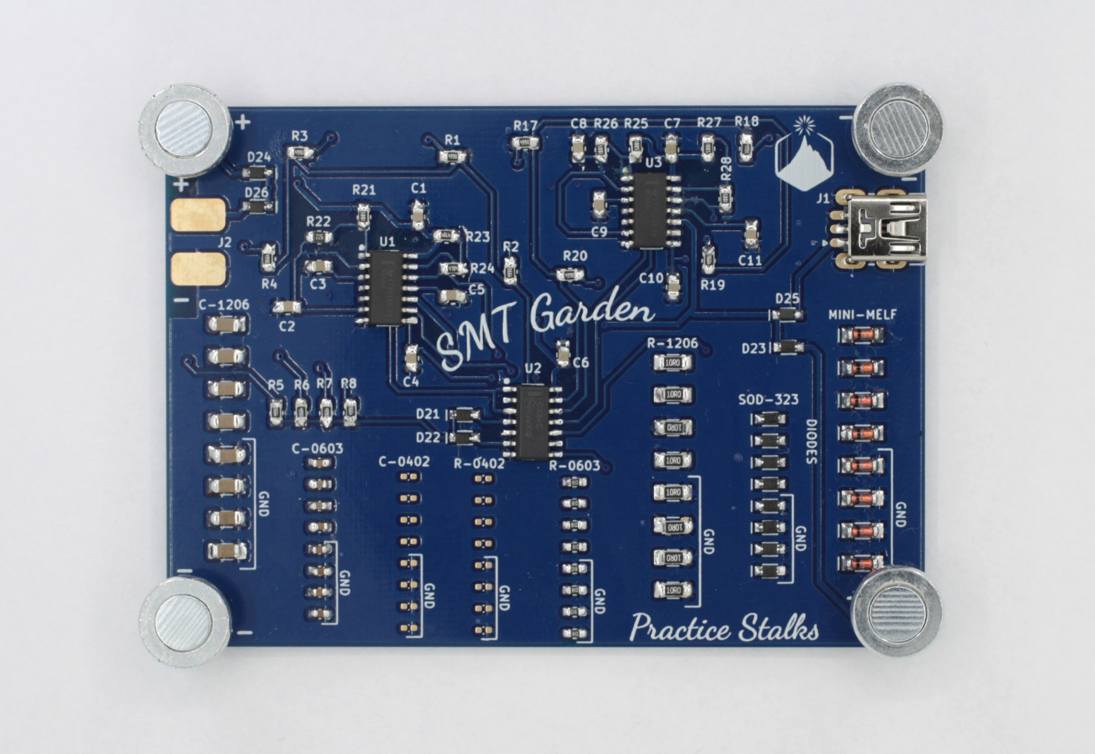
SMT Garden
Step by step instructions for our Learn to Surface Mount Solder board.
Discussions
Become a Hackaday.io Member
Create an account to leave a comment. Already have an account? Log In.