# Jog wheel board
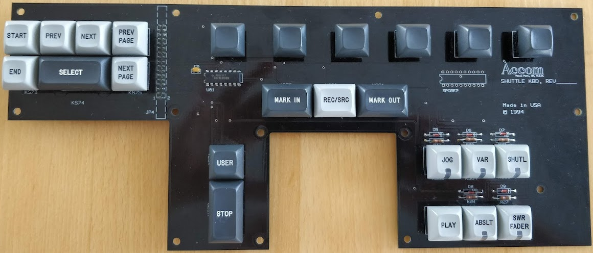
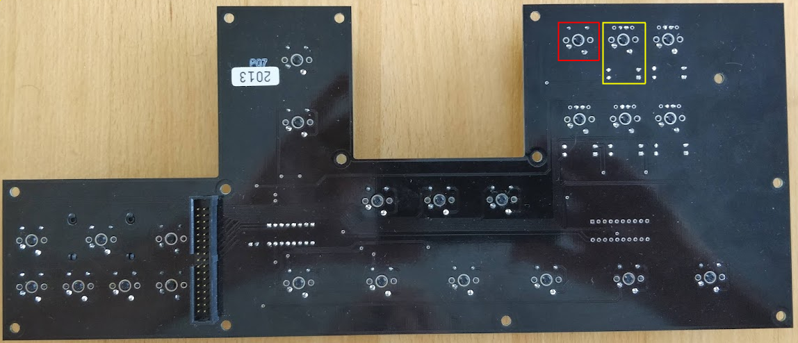
This board holds 24 keys and 5 LEDs.


The keys on this board are far from as orderly laid out as on the function board, so mapping them is also rather more messy.
Arbitrarily numbering things:
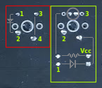
- key switches (red frame in above image):
- pin 1 is connected across various keys
- pin 2 is connected across various keys
- pin 3+4 are shorted to pin 2 when the switch is pressed
- between pins 1 and 2, there is a diode within the switch casing
- lighted key switches (yellow frame in above image):
- pin 1 is connected across various keys
- pin 2 is connected across various keys
- pin 3 is negative terminal for LED
- in this case, the pin 1 diode is external to the switch casing
Surprise: this board uses the same demultiplexer select lines (23, 25, and 27) as the function board. Perhaps other G1/G2 settings, then? Yes: G1 is pulled high and G2B is pulled low as above, but G2A is routed to its own ribbon line (19), and should be pulled low when scanning.
As before, pin 1 on the key switches are run directly to the ribbon cable, and pin 2 on the key switches are run through a demultiplexer. Also as before, the demultiplier outputs and the return lines are active LOW, so all except the signalled line(s) will be set HIGH.
Demultiplexer
|
Pin |
In |
Out |
|
1 |
Select A |
|
|
2 |
Select B |
|
|
3 |
Select C |
|
|
4 |
G2A |
|
|
5 |
G2B hardwired to GND |
|
|
6 |
G1 hardwired to 5V |
|
|
7 |
|
unused |
|
8 |
GND |
|
|
9 |
|
unused |
|
10 |
|
unused |
|
11 |
|
unused |
|
12 |
|
unused |
|
13 |
|
[REC/SRC], [MARK OUT], [JOG], [VAR], [SHUTL], [PLAY], [ABSLT], [SWR FADER] |
|
14 |
|
[END], [SELECT], [NEXT PG], [STOP], [MARK IN] [VFD 1], [VFD 3], [VFD 5] |
|
15 |
|
[START], [PREV], [NEXT], [PREV PG], [USER], [VFD 2], [VFD 4], [VFD 6] |
|
16 |
5V |
|
So it would seem that, to scan this board, I need to run a binary sequence 0-2 through ribbon lines 23, 25, and 27 to power the jog board keys (pin 2) as follows:
|
int |
bin |
r27 |
r25 |
r23 |
IC pin |
output (to key switches pin 2) |
|
0 |
000 |
L |
L |
L |
Y0, pin 15 |
[START], [PREV], [NEXT], [PREV PG], [USER], [VFD 2], [VFD 4], [VFD 6] |
|
1 |
001 |
L |
L |
H |
Y1, pin 14 |
[END], [SELECT], [NEXT PG], [STOP], [MARK IN] [VFD 1], [VFD 3], [VFD 5] |
|
2 |
010 |
L |
H |
L |
Y2, pin 13 |
[REC/SRC], [MARK OUT], [JOG], [VAR], [SHUTL], [PLAY], [ABSLT], [SWR FADER] |
|
3 |
011 |
L |
H |
H |
Y3, pin 12 |
unused |
|
4 |
100 |
H |
L |
L |
Y4, pin 11 |
unused |
|
5 |
101 |
H |
L |
H |
Y5, pin 10 |
unused |
|
6 |
110 |
H |
H |
L |
Y6, pin 9 |
unused |
|
7 |
111 |
H |
H |
H |
Y7, pin 7 |
unused |
Any pressed key switches (pin 1) should then be signalled on (odd-numbered) ribbon lines 1-15:
|
key switches pin 2 output |
ribbon line |
|
[PREV], [MARK IN], [REC/SRC] |
1 |
|
[START], [END], [MARK OUT] |
3 |
|
[SELECT], [NEXT], [PLAY] |
5 |
|
[PREV PG], [NEXT PG], [JOG] |
7 |
|
[VFD 1], [VFD 2], [VAR] |
9 |
|
[VFD 3], [VFD 4], [SHUTL] |
11 |
|
[VFD 5], [VFD 6], [ABSLT] |
13 |
|
[USER], [STOP], [SWR FADER] |
15 |
Additionally, 5 of the keys have LEDs; these are all supplied with the same 5V from ribbon line 6/8/10 and individually lighted by pulling pin 3 down via separate ribbon lines.
So in short, here is my new knowledge about the ribbon cable:
|
Ribbon line |
Source |
Signal |
|
1 |
Jog board |
[PREV], [MARK IN], [REC/SRC] |
|
2 |
Main board |
GND for [VAR] LED |
|
3 |
Jog board |
[START], [END], [MARK OUT] |
|
4 |
Main board |
GND for [JOG] LED |
|
5 |
Jog board |
[SELECT], [NEXT], [PLAY] |
|
7 |
Jog board |
[PREV PG], [NEXT PG], [JOG] |
|
9 |
Jog board |
[VFD 1], [VFD 2], [VAR] |
|
11 |
Jog board |
[VFD 3], [VFD 4], [SHUTL] |
|
13 |
Jog board |
[VFD 5], [VFD 6], [ABSLT] |
|
15 |
Jog board |
[USER], [STOP], [SWR FADER] |
|
19 |
Main board |
Jog board G2A |
|
29 |
Main board |
GND for [SWR FADER] LED |
|
31 |
Main board |
GND for [ABSLT] LED |
|
33 |
Main board |
GND for [SHUTL] LED |
 noughtnaut
Discussions
Become a Hackaday.io Member
Create an account to leave a comment. Already have an account? Log In.