It's time to implement keypress detection for the 18 lighted switches. The two demultiplexers "M" and "N" share a number of their inputs; "DMX SEL" (pins 1, 2, and 3), as well as "G2B" (pin 5) and "G1" (pin 6). Again, both these demultiplexers are socketed, allowing me easy access to tap into their pins. However, "G2A" (pin 4) are addressed separately; and the respective outputs go to the "output enable" pins ("G1" and "G2", pins 1 and 19) on the bulb control chips "D", "E", and "F" (for "M") and the key sensors "J", "K", and "L" (for "N").

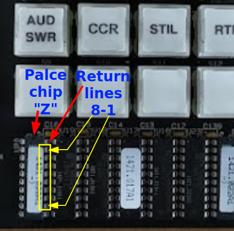
As stated previously, I'll need to provide DMX SEL signals for the LS138 "N", and read out signals on pins 12-19 of one of the PALCE chips ("T", "V", "X", and "Z" -- they're all connected in parallel). I'm going to solder leads from the ribbon cable to a chip header which I can then drop into one of the PALCE sockets on the board. Oddly, the long green patch wire connects "B Select" from "M"/"N" to pin 31 on the VFD daughter board; this is not used by the VFD, so what is its purpose?

On the Teensy side, I can re-use the same pins for the "DMX SEL" and return signals as for the rest of the keyboard interface, and I'll dedicate two pins for "G2A" signals.

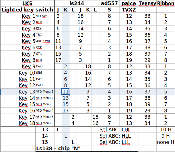
So for instance, to test whether the [VFD Menu 1] key (#13) is being pressed, I should set the VFD ribbon line 9 to HIGH, and lines 10, 11, and 13 to LOW, and then check for a LOW return on ribbon line 5. Why this is, is a bit convoluted:
Pressing LKS #13 sets pin 11 on "K" to LOW. To enable the output pins on K", we'll also need to set pins 9+19 (corresponding to VFD ribbon line XXXXXXXXXXXX) to LOW. This signal we get from pin 14 on "N", where configuring its "DMX SEL" to "H/L/L" (corresponding to ribbon lines 9-11), as well as setting its "G2A" LOW, will output a LOW. Now that "K" has a LOW input from LKS #13 and its outputs enabled, it can pass that LOW state to pin 16 on the "TVXZ" sockets, which is connected to VFD ribbon line 5.
I've expanded my existing kepboard driver to include the "G2A" pin of demultiplexer "N" to scan the lighted keys. The "DMX SEL" signals are used differently than for the other keyboard parts; rather than using the entire binary sequence they are simply addressed one-by-one. Therefore, I've modified my driver's sequencing to not run through the full 0b000-0b111 sequence but only 0b000, 0b001, and 0b010, so that the scanner doesn't waste time checking dead leads. For code efficiency, on the "L" chip 6/8th of the return line scan will be superfluous, but in terms of response time that's (hopefully 🤞) negligible.
Update: The problem with the stricken section is that the keypress return lines of the VFD ribbon cable are active LOW, while the keypress return lines of the keyboard ribbon cable are active HIGH. 😑 I will need to add some TTL components to invert the 8 return lines of the VFD ribbon cable, and I plan to do so in the form of a daughter board in between the 34-pin box socket and the VFD ribbon cable.
I've yet to do the solder work to see if it works as intended (ominous foreshadowing).
 noughtnaut
Discussions
Become a Hackaday.io Member
Create an account to leave a comment. Already have an account? Log In.