-
14.10.2022 First Milestone Achieved
10/12/2022 at 21:45 • 0 commentsUpdate on 14.10.2022:
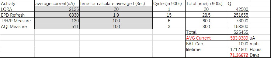
1. In order to calculate the estimate battery life time, we need to know the current consumption for the sensor node at different stages. In this case it's mainly include:
A. All the devices sleep/suspend (around 1.5uA to 2.5uA)
B. EPD refresh
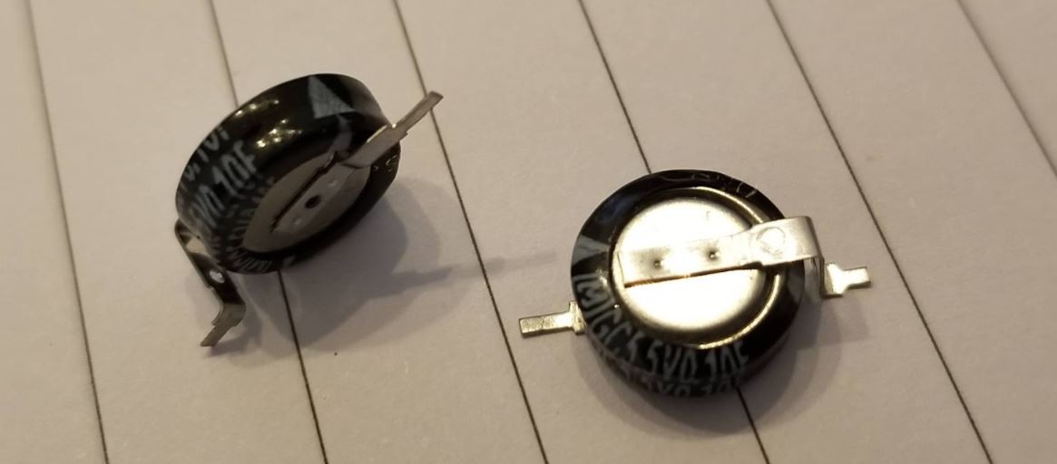
C. BME680 measure T&H&P
![]()
D. BME680 measure AQI(gas)
![]()
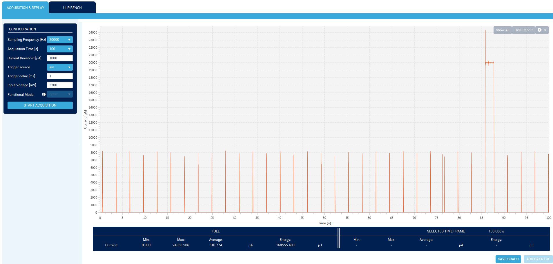
E. STM32WL send data to LoraWan(TTN) and open receive windows(RX1/RX2)
![]()
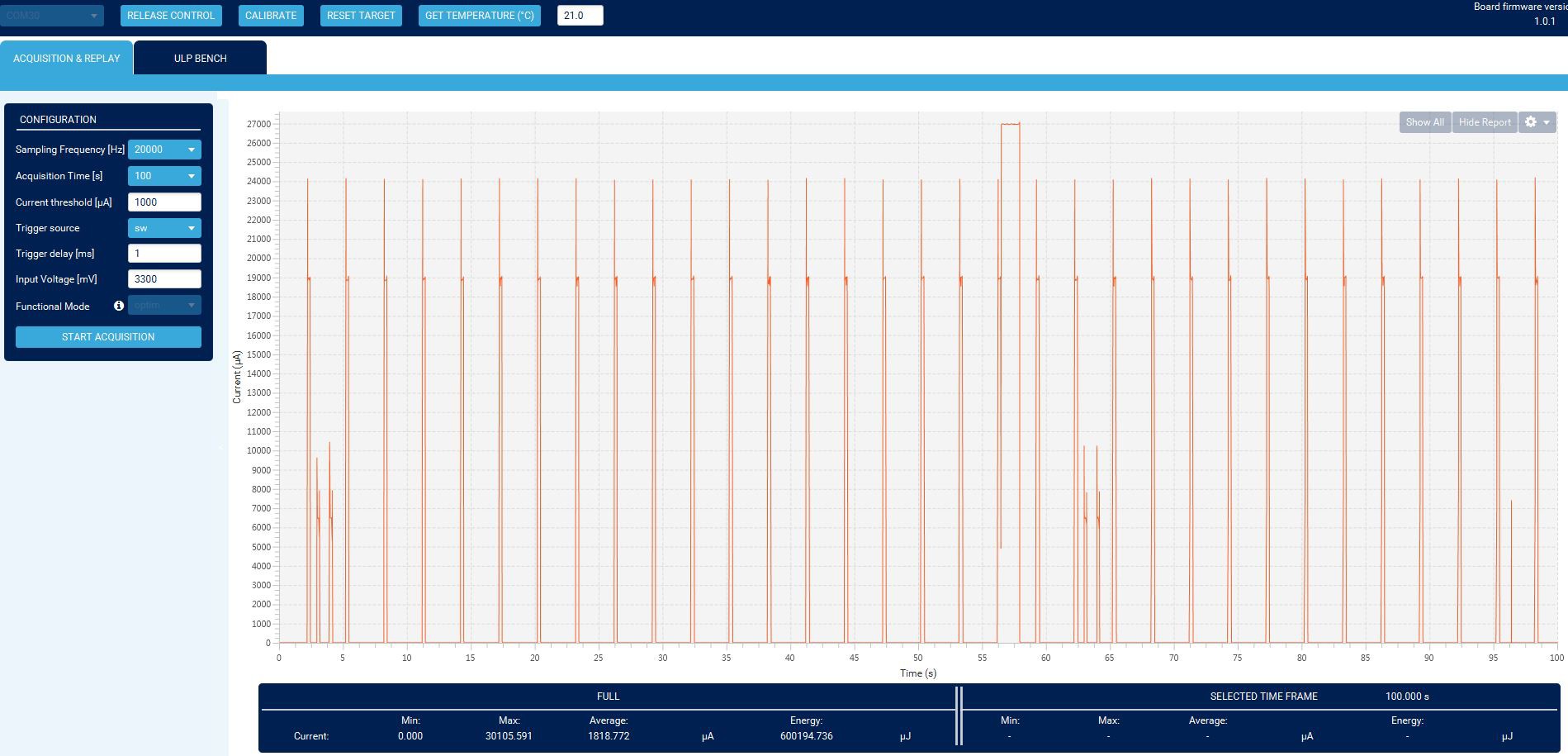
make a rough calculation, the system can running around 2 months, with EPD refresh once every minute, AQI update every 5 mins, and commit date to TTN every 15 mins. And it seems not bad.
![]()
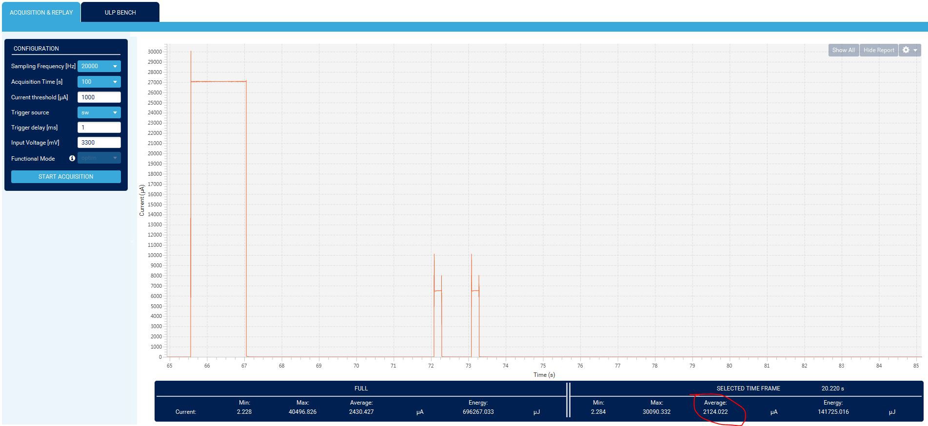
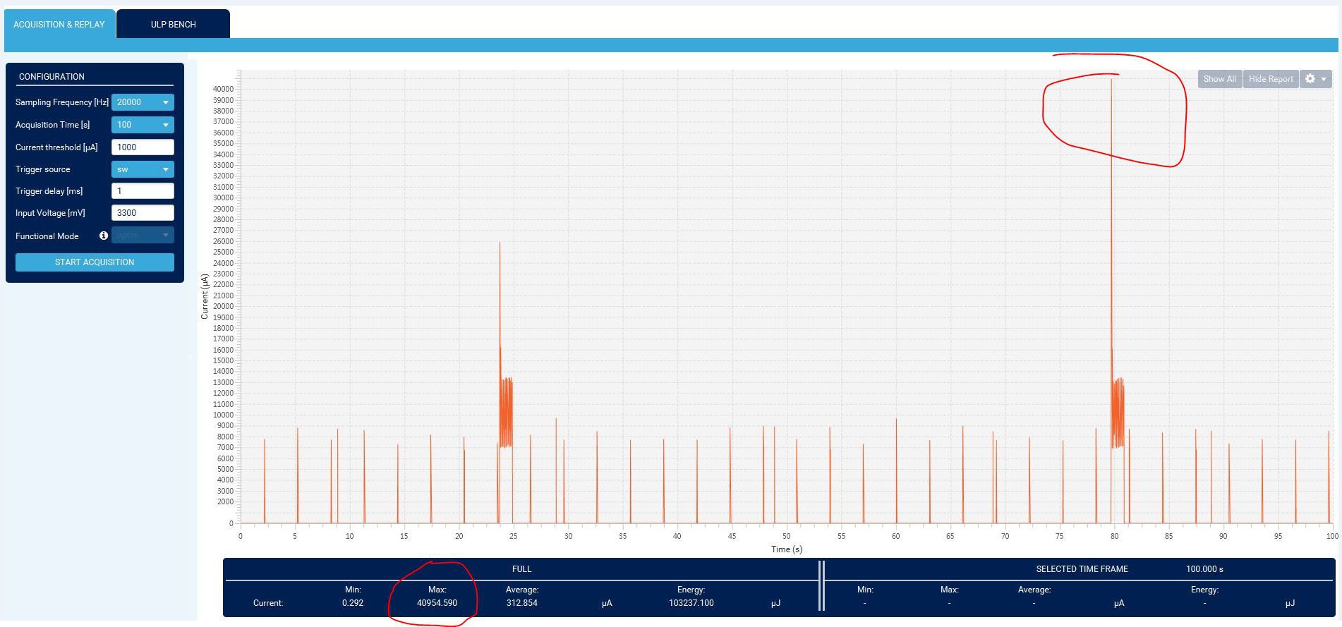
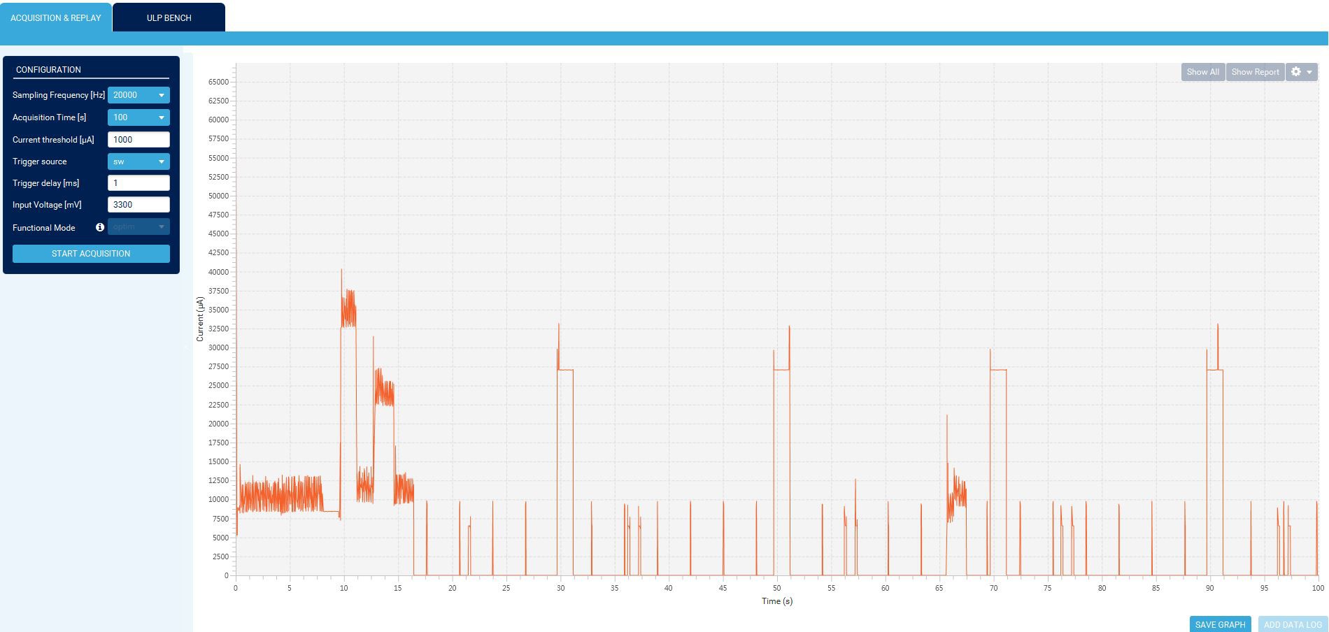
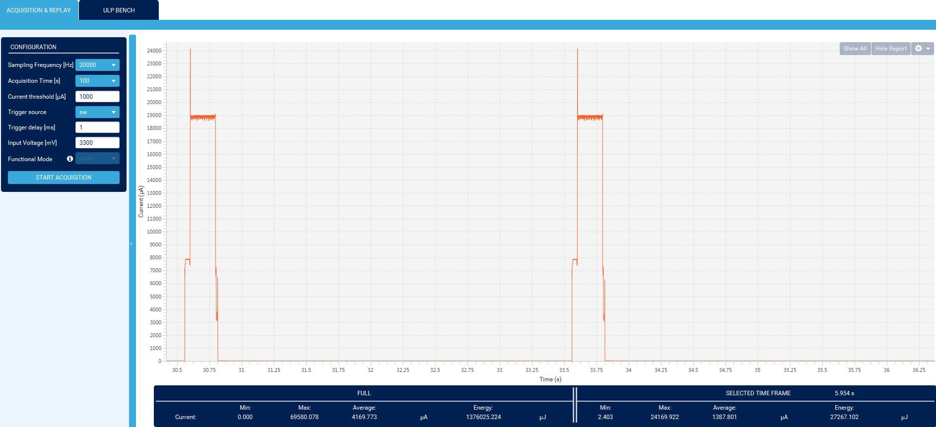
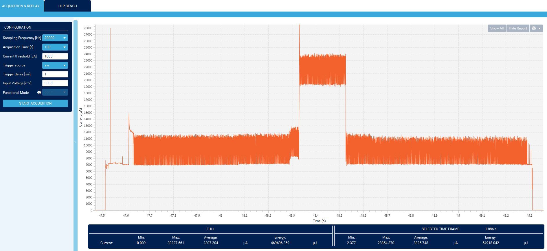
But when I build another one in order to test the real battery lifetime, the Node stopped working after several hours, even it equipmed with 2 new CR2450 batteries. then check the battery voltage, it's only around 2.6V, the nominal value is 3V, and new battery voltage is 3.3v, it's dropped to fast. Then reconnect the 2.6V batteries with the node, it works again. After analysis, found it's caused by the peak current when the RF working together with EPD refresh, in some conditions the BME680's heater also workings in parallel. At this moment, the peak current is more than 100ma, which is far beyond the poor battery's capacity. There is no detail specification for the peak current of CR2450 battery, Energizer said it's 9mA(https://data.energizer.com/pdfs/cr2450.pdf), Murata said it's new battery CR2450R: "The maximum pulse discharge current*1 has been doubled to 50mA compared to that of Standard. "(https://www.murata.com/en-global/products/productdetail?partno=CR2450R), which means the standard CR2450 can provide 25mA peak current.
This current waveform captures the EPD refresh and Lora send, it's already over 40mA, and the battery doesn't survive when the AQI sensor's heaters (plus ~16mA 1.6s) work in parallel..
![]()
I want to order Murata's CR2450R battery, but found the delivery time is quite long due to they are "dangerous goods". Then using supercapacitor is also may a solution, even it may has several uA leakage current , I found out out 2PCs 0.1F/5.5V supercapacitors which purchased 2 years ago, but found they are defected, they don't have any capacity anymore.
![]()
I nearly want to give up, then checked the STM32WL55 datasheet again, found there is an application note to reduce the RF power. After optimization, the peak current for RF reduced from 33mA to 20.5mA, the SNR seems not influnced by the optimization.
Before RF Optimization:
![]()
After Optimization:
![]()
encouraged by this, I creat a new Look Up table for the EPD partial refresh, which reduce the partial refresh time from 1.8s to 1.2s, the payback is stronger afterimages. but it doesn't matter, after 10 cycles(equal 10 mins) faster refresh execute one time slower partial refresh. And make a full dispay refresh every 2 hours.
Then add status machine to avoid EPD/RF/AQI_Gas heater working in parallel, in this way we can limit the peak current within 25mA, which means ideally 12.5mA peak current for each battery.
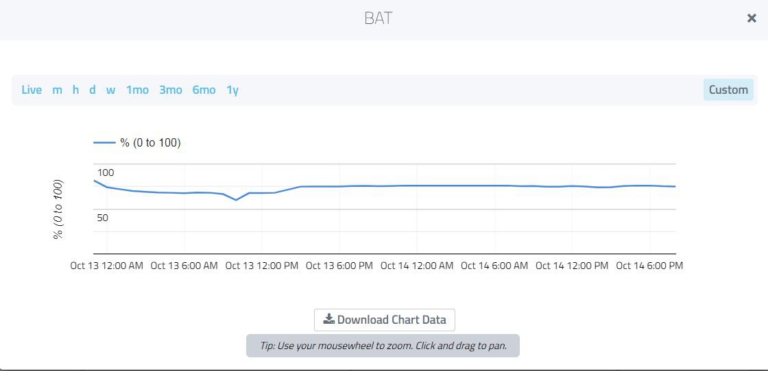
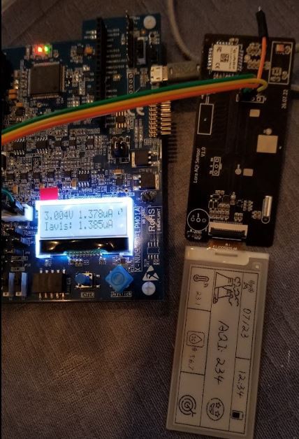
To check what's the real battery lifetime, a new battery is installed in the Node at running from 12.Oct evening, let's see how long it can last(seems the battery voltage strongly influnced by the temperature).
![]()
2. Some interesting tests
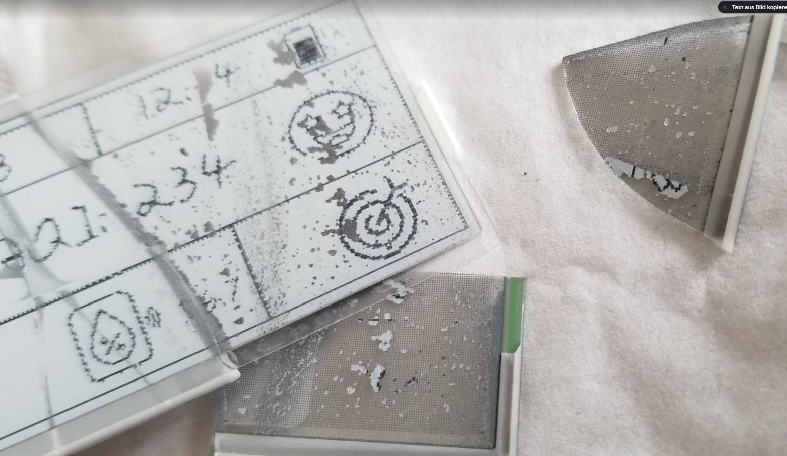
2.1 Put the Node into the refrigerator freezer(-18deg), the EPD can't working under this low temperature but it can recovery when the temperature recovers.
![]()
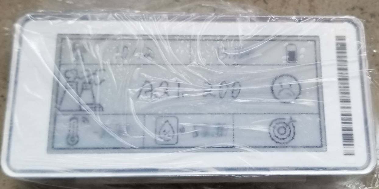
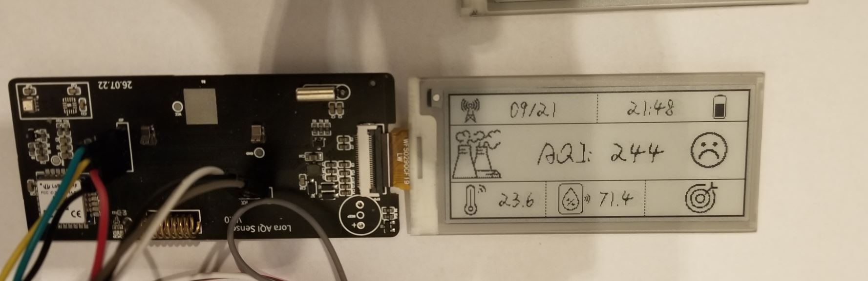
2.2 The cracked EPD can still keep the last image
![]()
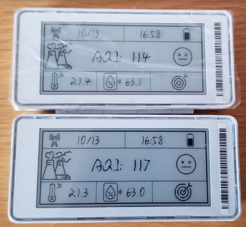
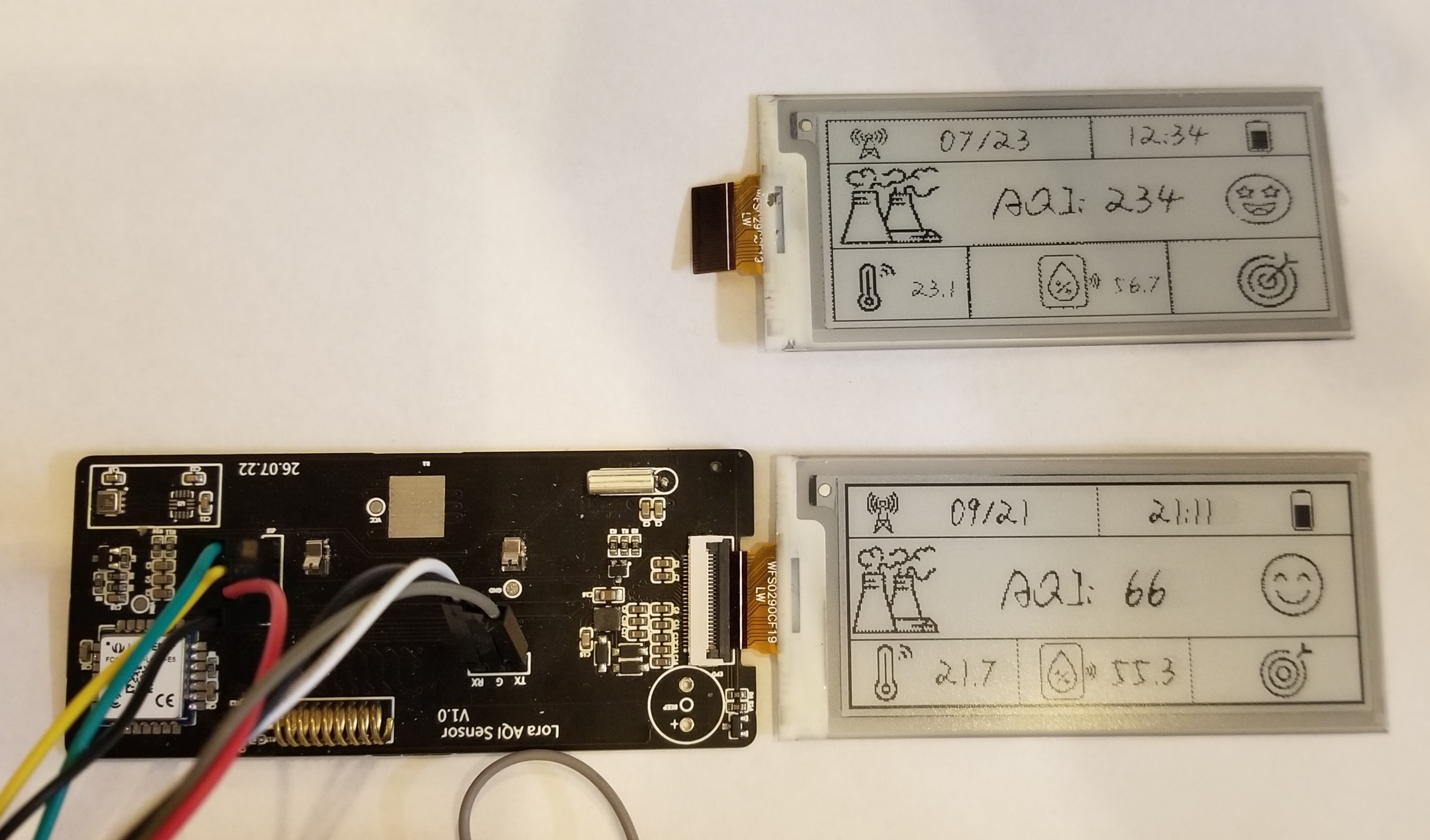
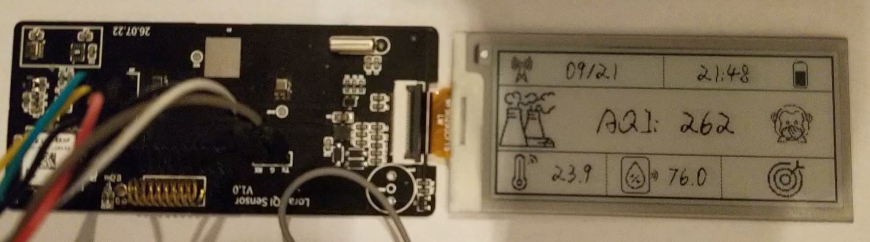
2.3 Two Sensor Nodes has similar measurement result
![]()
2.4 The PCB antenna has similar SNR as the spring antena when the housing is not mounted, but when the housing is mounted, the PCB antenna is around 1.5db weaker then the spring antena. This may caused by the PCB antenna is partialy covered by the battery, which has metal housing.
You can find the PCB gerber file and FW for the MCU, having fun.
-
05.10.2022 Update:
10/05/2022 at 20:39 • 0 comments05.10.2022 Update:
There is not much free time recently, so the update is slowly.
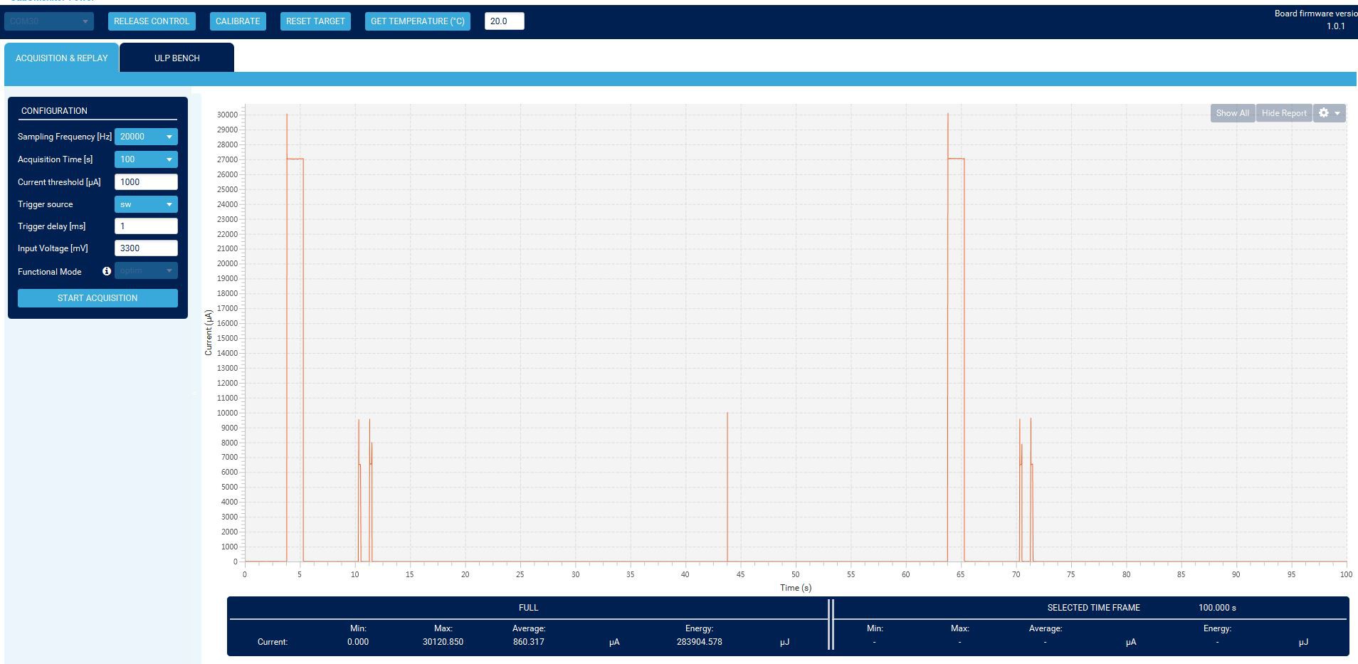
1. Struggling with the low power mode: At beginning, the boad suspend current(MCU in STOP2, EPD & BME680 are in sleep mode) more than 600uA, even removed the EPD, the suspend current is not reduced.
2. The BME680 is suspected, the heatter seems on by default, then send command to turnoff the heater, but it doesn'r help either.
3. Suspect the soldring paster cause current leakage(the 1st soldered with hotplate), or the Lora-E5 or BME680 get damaged due to ESD issue. Then take another PCB, after make sure the PCB is without leakage current, solder this board carefully with iron, only put lora-E5 module and EPD driver on it. After testing, the suspend current is still too high, around 400uA.
4. Connect the board to the debugger, together with a DIM, debugging code and check the relative current change.......
5. Finally found we need to set the used pin to analog mode to save current, before I set them as input with pullup / pulldown resistor, which consume much more current than analog mode.
6. Solder BME on the board, the suspend current has no big difference. Now the 2nd board suspend current is ~ 1 . 5uA, but the 1st board suspend current is still higher, around ~ 2.4uA. The root cause is unknown, maybe by devices deviation.
![]()
7. Debug each SW modules, make sure they are working fine after the CPU recovered from Stop mode. and they can't let the system caused addtional current during system suspend mode. Struggling a long time with the SPI recovery after stop mode.
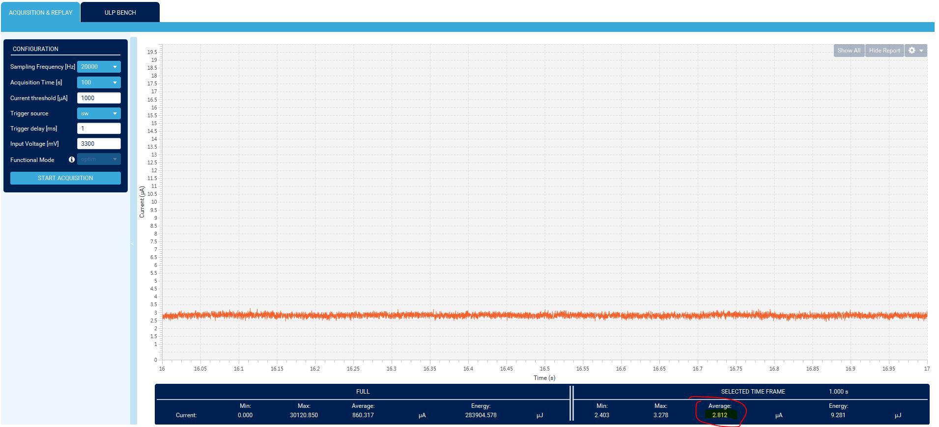
8. Now the system running with BME680 LP mode(sensor date update every 3 Secs), Send data to TTN every 60s(with TX_POWER_11 due to the current mesurement device limitation), EPD partial update every 56 Secs. Here are some current data:
A: BME680 sleep, Lora TX current.(1st peak is TX data, 2nd is RX1, 3rd is RX2, 4th is a timer wakeup CPU)
![]()
B: Suspend current, this is the 1st board with higher suspend current
![]()
C: BME680 working current(it makes a measurement every 3 Secs, at 57s there is a Lora TXD)
![]()
D: Zoom in for BME680 one measurement:
![]()
E: EPD partial update current:
![]()
9. it seems each activity will consumes a lot of energy, so the plan will be set the BME680 working with LP for T/H/P sensors, and ULP for AQI sensor, the EPD will be partially update every 56 secs in order to display the time correctly. And Lora commit data to TTN every 15 mins or the sensor data changed a lot, maybe 20% within 15mins. The EPD will make a full refresh each 2 hours to avoid shodaws like this:
![]()
![]()
![]()
10. The historical chart will be add later, hopefully all of this can be finished in Oct. Then I can share the firmware here for those interested.
-
21.09.2022 Update:
09/21/2022 at 20:41 • 0 comments1. EPD partial update is working well now, the driver provide by Waveshare(seems a wrap of Good-Display‘s driver) give a serious afterimages when using partial update, after modify the LookUpTable, it works fine now. But after update the LUT, the partial update time takes 1.2s. The advantage is the display doesn't have obvious afterimages after one night running (around 1000x partial update).
2. Basic font are ready to us, the font width is dynamic, in order to have the "handwriting effect", but since there are only few characters shows on the display, so it doesn't make much sense.
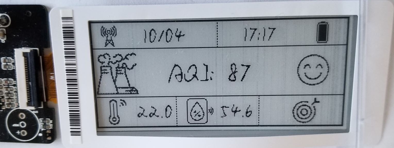
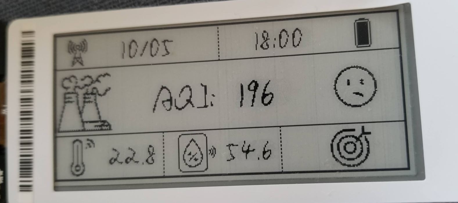
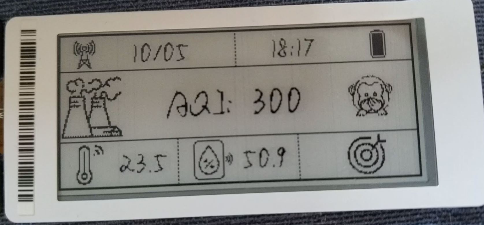
3. Icon images are ready, there are 4 dynamic icons: LoraWan joinned status(0 and 1) / battery level (0-19) / Emoji for AQI(1-7) / AQI accuracy level (0-3, the right down target icon). (Before this, the EPD just show a UI picture)
4. Get time from LoraWan server (TTN) is working, by using deviceTimeReq MAC command after the device joined the LoraWan.
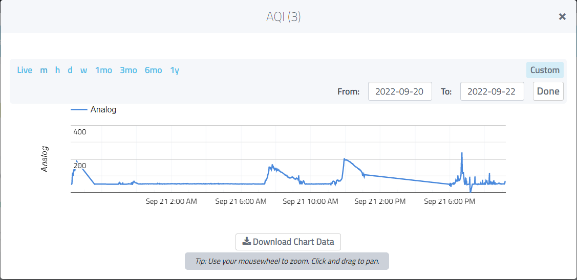
5. Cayenne LPP works fine till now, it has a user friendly UI, you can check the historical data easily.
![]()
![]()
![]()
![]()
There still a lot of todos:
HW side:
1. Soldering the beeper and 2 LEDs on the PCB, when the AQI level is very bad, then beep 2 seconds.
2. Remove the battery voltage circuit on the PCB, since it's duplicated, to reduce the leakage current.
3. Test the PCB antenna and the spring antenna, check which performance is better.
SW side:
1. store the lora configuration into the EEPROM, to avoid "DevNonce is too small" problem in TTN when the device rejoined the TTN net. (when the TTN console report this error, the device still can join the TTN net after a certain time, but this will use a lot of energy )
2. Store BME680 sensor status info into flash, to avoid the long initial time(2-5 mins) of BSEC.
3. Set BME680 into Ultra-low power mode, T/P/H update period is 3secs, AQI update period is 300s. Set the EPD update rate to 30sec, display the 10 measurements mean value of Temperature and Humidity on the display.
4. Comit sensor's data to TTN once per hour, the data contains the sensor's Max/Min/Mean value during this 1 hour.
5. Using the varibration sensor to change the EPD UI, show the last 5 day's temperature & AQI data.
6. Set Seed-E5 module into stop mode with RTC/EXTI wakeup, in order to save power.
7. Test the whole system dynamic current consumption and optimize it, evaluate the battery lifetime
usage extension:
Due to gas crisis in Germany, the temperature in the office may not over 19 deg this winter, seems my office covered by TTN, so if it's too cold there, I can choose Homeoffice. And if the AQI is bad, the beep can notice me to open the window for a short time.
LoRaWAN AQI Sensor With E-Paper Display
This is a lowpower consumption Air Quality sensor, it measures T/H/P/AQI and commit the data to LoraWan(TTN), together with a E-ink Display.