-
Component Power Consumption
10/18/2022 at 03:48 • 0 commentsTest Results
Individual Component Power Consumption
Raspberry Pi 4 ~580-700mA Raspberry Pi Zero W ### 8" Display and Driver Board (35%, 50%, 75%, 100% Brightness) ~425, 490, 610, 750mA 5" Display and Driver Board (50%, 75%, 100% Brightness) ### 8Bitdo Controller (using currently)*** ~40mA TeensyLC Controller (will use in final system)*** ### Mono Amplifier w/ 3W Speaker*** ~8-20mA Fan Style 1 ~35mA Fan Style 2 ~170mA WIFI disabled ### Headphone Jack*** ### Bluetooth Headphones*** ### Total of Currently Used Components ### ***Note: component powered by Raspberry Pi
Battery Runtime Test #1 (Rpi4, 8" display @100% bright, 3W audio, 8Bitdo ctrl, NES emulator running)
Indicator LED Description Capacity
CalcTotal
Runtime
(min)Total
Runtime
(H:MM)Lap
Time
(H:MM)4 LEDs lit 100% 0 0:00 0:00 3 LEDs lit 95% 12 0:12 0:12 2 LEDs lit 64% 92 1:32 1:20 1 LED lit 32% 173 2:53 1:21 1 LED blinking 24% 194 3:14 0:21 Power Down 0% 256 4:16 1:02
Battery Runtime Test #2 (Rpi4, 8" display @50% bright, 3W audio, 8Bitdo ctrl, NES emulator running)
Indicator LED Description Capacity
CalcTotal
Runtime
(min)Total
Runtime
(H:MM)Lap
Time
(H:MM)4 LEDs lit 100% 0 0:00 0:00 3 LEDs lit 84% 49 0:49 0:49 2 LEDs lit 56% 140 2:20 1:31 1 LED lit 32% 216 3:36 1:16 1 LED blinking 26% 234 3:54 0:18 Power Down 0 316 5:16 1:22 [10-18-2022]
I finally received the replacement battery charger PCB and have a fully charged battery! This means that it's feasible for me to power the console back on. I've got a little USB power meter that will allow some measurements to be taken on the individual components in the console. These measurements aren't strictly necessary, but are really just for the curiosity of it. And I'm especially curious how the measured power stacks up against the 10,000mAh battery and what kind of runtime I'll get. From my limited experience with batteries, I believe that the rating is referencing the total energy capability of the battery. And because the system will need to be shutdown before all the energy is discharged (@ about 3.5V), this means the entire rated mAh isn't usable energy and the "effective" battery rating will be lower than 10,000mAh.
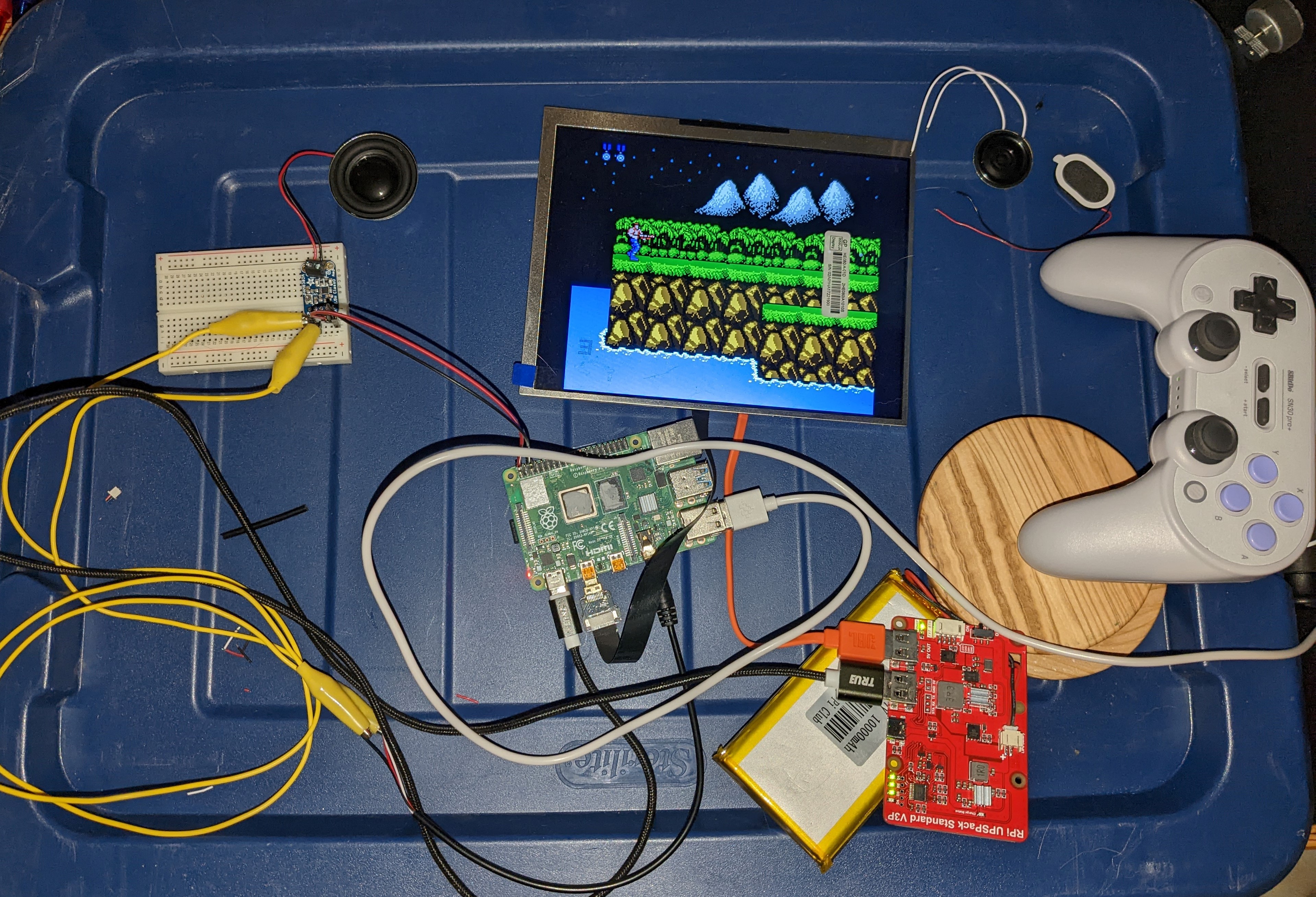
Here's a picture of the console guts with an 8Bitdo controller instead of the final TeensyLC controller. Also note from this picture that I am testing out speakers and the amplifier board right now and will create a separate log for that process.
![]()
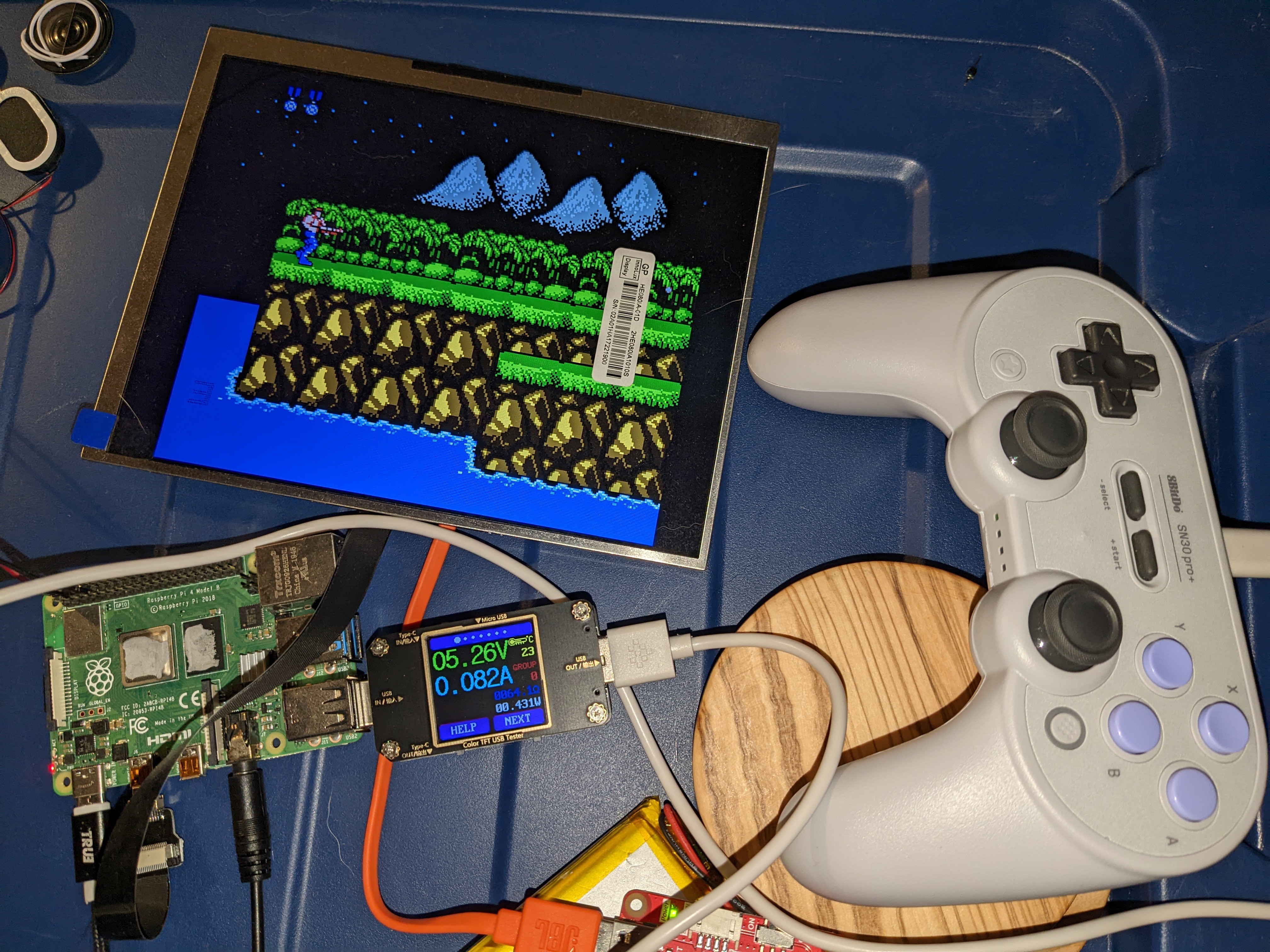
And here is a picture showing the USB power meter connected to the controller USB cable. I tried to take the highest consistent peak that I was seeing from the meter when creating the table below.
![]()
And finally, here is a table listing the power consumption for each component. For components powered by the Raspberry Pi, I first took a base measurement of the RPi without anything connected to it. Then I took a measurement with the component attached and subtracted the base measurement.
[11-27-2022]
So, I had originally thought that measuring the power consumption of each component in this project was unnecessary and only served to satisfy my curiosity. However, after actually making some of the measurements, the process actually highlighted a couple areas of concern.
First of all, my testing process wasn't the best and was causing the measurements to be weirdly low. I was measuring power with the components connected to the battery, and started noticing the Rpi throwing out a low voltage warning. I have a suspicion that the battery charger board has a high-ish output impedance, and I'll plan on investigating it at some point. This also prompted me to find an alternative battery charger for comparison. And after measuring the power consumption of components while connected to outlets instead of battery, the measurements shot up closer to values I was expecting.
The second area of concern is the battery life. From the testing I have done, the battery life has been abysmal. To the point that if I can't find a way to improve it, this project may be dead in the water. I haven't tested it well yet, but it seems like I'm only getting about 2 hours of play time out of the 10,000mAh battery at this point. This prompted me to find an alternative 5" display and to dig out my Raspberry Pi Zero W so that I can test their power consumption as well. I'm hoping that these measurements help me see any areas of improvement.
And finally, I have updated the table of measurements in the previous post with new values.
[12-04-2022]
I have moved the table of power measurements to the top of this post and have also added a couple tables documenting results from some tests that I completed this week. The tests were to simply fully charge the battery and run the system until it powered off to see how long it would last. I ran the test twice, once with the screen at 100% brightness and once at 50% brightness. The process and results are documented more below.
Given the doubts that I had about the battery/charger board in previous posts, my expectations with this test were pretty low. And the results are pleasantly surprising! The punchline is that the battery lasted for 4:16 (H:MM) with the display at 100% brightness, and 5:16 at 50% brightness.
There were two misunderstandings that I uncovered which previously made the battery life seem poor. One is that I wasn't fully charging the battery. The incorrect assumption that led to this was that if all 4 battery level LEDs were on, that the battery was 100% charged. This isn't correct, and the 4th level indication LED will turn on much earlier than full charge. Like, somewhere between 1 and 2 hours prior to full charge. The correct way to determine full charge is to pay attention to the charging status LED. This LED blinks when charging and then turns solid when done charging.
The other misunderstanding was what it means when the last of the level indication LEDs starts blinking. I assumed that this meant power down is eminent and so I would power off or switch to non-battery power. But after running these tests, it looks like the battery has roughly an hour of runtime after the indicator starts blinking. Looking at the testing results in the tables at the top, it just seems to me that the time going from 4 LEDs down to 2 is non-intuitive compared to the actual runtime of the system. My takeaway is that with 2 LEDs, the battery is just above 50% capacity. And when the 1st LED starts blinking, then there is roughly an hour left on the battery.
An interesting exercise is to compare the tested battery discharge time to an estimated theoretical value. I'm estimating from the table at the top that the Rpi4 and 8" display use 1,140mA at 50% brightness, and 1,400mA at 100% brightness.
10,000mAh @ 3.7Vdc = 37,000mWh
37,000mWh = 7,400mAh @ 5Vdc0
0.8 * (7,400mAh / 1,140mA) = 5.2hr (50% brightness)
0.8 * (7,400mAh / 1,400mA) = 4.2hr (100% brightness)
This theoretical calculation actually matches the tests very well. Notice that I applied an 80% factor in the last step. This accounts for unused capacity left in the battery at the point that the charger board shuts it off. My surface level understanding of this is simply that the 10,000mAh rating of the battery represents the total energy stored. In order to use all this energy, the voltage would have to be run down to or close to 0V. And since the charger board shuts the battery off around 3.3V the entire battery capacity is not utilized. I have no idea if an 80% utilization factor makes sense, but it seems reasonable.
I'd still like to test out the current draw and battery discharge times of my Pi Zero W paired with a 5" display, but have misplaced the HDMI adapter needed for the Pi Zero W. The 5" display will also need a custom cable made to power it, so I'll save this for another time.
-
Current Status of Design
10/07/2022 at 07:36 • 0 comments[10-07-2022]
So, I started this project page quite a ways into my effort for the project. This project log is intended to review what I've done on the project to this point. With that said, here are some design aspects along with their status:
Processing and Software
The brains of the console are run from a Raspberry Pi 4 model B. I think that it's got 4gb of RAM, but am having a hard time pulling up the Ebay page that I purchased it from to see. So, I'll have to figure out how to find that info in the RetroPie OS the next time I turn it on.
RetroPie is successfully installed on an SD card and a lot of the initial setup is done. A keyboard is connected via Bluetooth, an IP address is setup and SSH enabled, and some games have been loaded and tested. There's definitely a lot more to configure here, including getting shaders dialed in for each console, testing the limits of running N64/Playstation games, and testing overclocking.
Display
The current display being used is an 8" IPS with 4:3 aspect ratio (1024x768). Honestly, this is a little bit larger than I'd like, but there just isn't much that I can find at the 4:3 aspect ratio. I am a bit worried that the end result will be too big and unwieldy, but we'll just have to wait and see. I originally tried a 7" 16:9 display (I was surprised at how much smaller the 7" 16:9 display was compared to the 8" 4:3, but it totally makes sense after thinking about it a bit... math!), and I couldn't accept having to choose between a skewed looking game or having black bars on the side.
This display is a Pimoroni product and comes with a driver board that interfaces to the LCD screen ribbon cable and provides an HDMI port for video from the RPi and a usb port for power. This has the advantage that it easily plugs into the RPi with an HDMI cable and doesn't require any special drivers or setup in RetroPie. I would have considered an LCD screen with a DSI interface if there was much available, but choices were limited. And it saves me from having to learn about DSI interfaces and install the correct drivers.
One lament that I have about the larger screen size is that it doesn't feel necessary for retro games. And being a portable device, weight and battery consumption are big considerations. Maybe the larger size will be a win if N64 and Playstation games run well, but I'm skeptical of the impacts of battery life and think that later generation games will require overclocking (further draining precious battery).
Audio
When all is said and done there should be three audio sources for the pandaPi. Bluetooth, speakers, and a headphone jack. I'm a little worried that if I put the effort in for the speakers and headphone jack, that I'll just fall back on bluetooth 100% of the time. But it just feels wrong to not have them as an option.
I have purchased a 2.5W Class D amplifier and a couple different speakers to test out for volume and sound quality. The initial test I ran was absolutely horrendous, very little volume and what sound did come out was only treble... after reviewing the connections I definitely didn't make the correct connections. Long story short, I didn't really understand the amplifier board terminals well before making connections. After re-viewing the terminals and what signals they are meant for, I believe that I've got it wired correctly now. Just waiting for a new battery to ship so I can try it out...
The plan is to simply extend the headphone jack to the console case via a perf-board. I'm going to try some Adafruit breadboard style perf-boards that look pretty slick. I know how to do PCB layout and could have a custom board manufactured, but it's expensive, time consuming, and I don't want to. I'm hoping that these Adafruit boards are a nice compromise that are more accessible than a custom PCB and also less sloppy than the old RadioShack perf-boards. And at the end of the day, if it came down to not having enough room inside the case, I would be willing to create a custom board to make this circuitry fit.
Controller
Now the controller seems like the most difficult piece of the equation (eh... the case is close behind). What makes it seem daunting is that I feel that this could make or break the system. It is going to be the difference between me wanting to use this console vs. just letting it collect dust. Early on I decided that the controller essentially needs to be some Frankenstein'ed version of a purchased controller that feels good. And I've gone down several rabbit holes investigating an approach for this. Initially, I got my hands on a PS5 controller with a broken joystick (easy fix). This controller has two separate PCBs for the D-pad and right hand buttons and these connect to a sort of motherboard using ribbon cables. I mulled over that one for awhile and decided against it for a few reasons: don't know the feasibility of getting longer ribbon cables to extend the buttons away from the motherboard, 3d modeling/printing a case to fit the same button profile would be complicated, and it consumes ~100mA which is high compared to other controllers I tested and not insignificant for a 10,000mAh battery.
The second idea that I landed on was to utilize a really nice 8Bitdo Pro 2 controller. Seriously, this controller is so nice! I don't really play games on PC anymore, but if I ever do, this controller will be my go-to. So popping it open, I was hoping that it would be simple enough to chop the PCB up with a dremell so that the buttons could be moved further out to the side. And then reconnect the button traces to the microprocessor that is interfacing to the usb port. It didn't take long after opening it up and looking at the PCB to understand that wouldn't be easy and would likely turn out just gross.
And finally, the current plan is to utilize some of the 8Bitdo pieces and a TeensyLC (Arduino) to create a custom controller. Admittedly, this approach is a little more involved than I wanted to go with, but I think that it will work without too much effort (knock on wood) and will turn out clean. This is based on an Xinput library that somebody else created (I'll provide links in future project logs and/or the build instructions page). I've tested this library with a TeensyLC and some tactile buttons as a proof of concept. So, from there I'm going to create some custom PCBs (one right, one left) which have the same layout membrane button traces as the PCB on the 8Bitdo. The custom PCBs will need to have the same shape and dimensions as the 8Bitdo PCB so that they can attach to the plastic chassis in the 8Bitdo. And when 3D printing the case, it will need to have the same button slots and tracks as the 8Bitdo controller. This will enable the use of the 8Bitdo controllers buttons and triggers in the custom PCBs/case. Even writing this just hammers home that this will be a large effort with lots of fine tuning. But I think I can do it. And this is probably hard to follow in words. At some point I'd like to create a project log going into more detail with pictures, PCB designs, etc.
Power Supply
The name of the game with the power supply is to get the largest battery that will feasibly fit in a portable console. I did find a 10,000mAh battery that comes with a charging controller from a company called MakerFocus. We'll see how it performs. The board actually already failed, but the company is sending me a new one. It could have been a mistake on my part that broke it... there is a JST connector that allows the use of an external button to turn the battery power on/off, and I was pretty sloppy in testing these pins and may have accidentally shorted the charger's positive and negative. I'm not sure, but am hoping that is what happened and that the new board will not give me any problems. If it does, then I'll just have to find another product. This charger board also has some communication capabilities and can send serial data to the RPi, so I might test that out at some point. I think that it may be used to signal to the RPi that the battery is low so that the RPi can shut itself down. I'm not super hopeful of getting this to work and don't think it will be terrible if it doesn't since the charger board has battery status LEDs that can be used as well. It will not be possible to have the power button shutdown the RPi softly. The RPi will need to be shutdown via the menu system, and then after it has shutdown the OS then the power button may be pushed. This is a little clunky, but I can live with it.
Case
And the last aspect of this project is the case. This is also the area that requires the most effort. I've recently bought a 3D printer and have been playing with it. I've also been learning Fusion 360 and just finished a tutorial series for it on Youtube. I've began modeling the 8Bitdo controller so that I can start fine tuning the button mounting. A ton of effort has been put into learning 3D modeling and it feels like there is a long way to go. I did just print the first prototype of the controller face and it turned out pretty good.
Mounting the electronics is another part that is unknown. I've experimented a small amount with a mounting option, but don't think it will work well. I've been browsing some other folks projects to see how they've accomplished this two. Lastly, the icing on the cake would be for the case to allow the screen to swivel slightly so that it could be viewed at different angles depending on if the user was sitting or laying down. I've got zero leads on a good way to accomplish that and am not counting on coming up with anything.