-
Extra PCBs / Improved Keyboard Controller
11/08/2022 at 03:10 • 0 commentsTwo quick things today:
I realized the PCB manufacturer actually sent me six PCBs instead of five. I've fully built up two, but I really don't need the others. If anyone is interested in assembling a board, I'd be happy to send you one. Let me know in a PM.
My first big update since the end of the Retro Challenge was to improve the PS/2 keyboard handling on both the CPLD and in the firmware. On the CPLD side, the scan code state machine now provides a way for the CPU to acknowledge receipt of the code. The CPU can poll a register to check for a key press and then write back to another register to clear the buffer once it has read the key value. This bit of back-and-forth makes it a lot easier to manage the state on the firmware side. The CPU will poll for non-0 key values and when it reads one, it writes the acknowledgment byte and the buffer value goes back to 0.
PS/2 scan codes come in with a "make" byte which is effective a key-down event, and a "break" byte which is always 0xF0 followed by the key-down byte again. The monitor firmware code can now handle this. It reads single key values and repeated (key held down) values and it can deal with out of order make and break bytes for multiple keys.
The serial monitor program had its serial input replaced with the PS/2 controller and its output replaced with the LCD display. The monitor is now fully functional without being tethered to a PC via serial port. The monitor features are still fairly limited, but my next goal is to write a driver for the CH376S USB module and this will allow me to load programs from USB.
It might be cool to add a simple assembler or interpreter so Flounder is fully programmable in addition to being able to load pre-compiled programs.
-
Retro Challenge Wrap Up
11/01/2022 at 00:50 • 0 comments![]()
Hard to believe a month has passed already, but here we are. It's the end of Retro Challenge 2022/10. As expected, Flounder is far from a finished product, but I'm still quite pleased with the progress. I am going to continue development, but I want to outline the current state of the project as a summary of what I accomplished in this challenge.
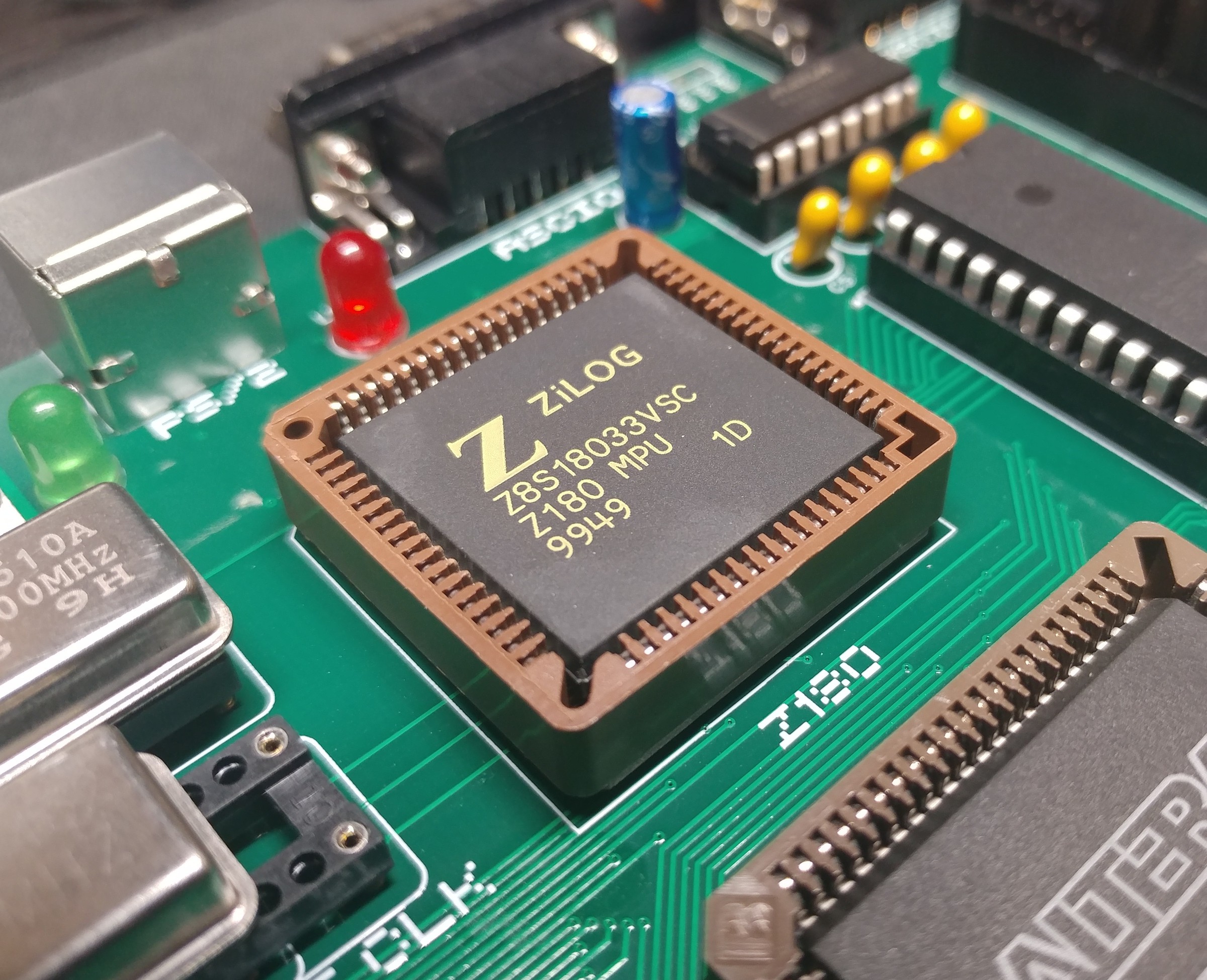
Going back to the original plan, my goal was to build a Z180 computer and have a PCB manufactured. At a high level, that goal was a success. Flounder Rev 1.0a is a working system, but of course, not every area is as polished as the others.
Here's the rundown:
Core System
The CPU, memory, and the built-in Z180 peripherals are working great. The two serial ports with their RS-232 circuitry are functional, and the internal timer hardware is being used to generate a periodic interrupt. The one feature I did not get to was the MMU. Although both the RAM and ROM are 512KB devices, the CPU can currently only access the first 32KB of each chip. Fortunately, this update can all be done in software.
CPLD
Responsible for address decoding, the ASCI clock, PS/2 interfacing, and random glue logic, the CPLD has proved to be a reliable conductor for the rest of the computer. Just about every control signal runs through it and having JTAG on board for in-circuit programming has been incredibly convenient.
PIO
I have only tested the two 8-bit GPIO ports in output mode. Currently, an LED is hooked up to port A and when the periodic system interrupt fires, the PIO increments the LED display by one. I'd like to create some hardware to test the input capabilities as well, maybe even bit-bang SPI.
LCD
The 40x4 screen is probably the most polished of the peripherals. Both the hardware and software is approaching completion. I implemented autoscrolling and a nice API in C making this easy to use in software. The next step here is to modify the monitor program to make use of the LCD as its primary display. Currently, Flounder is still reliant on the serial port for some functions.
Keyboard
The clock and data lines of the PS/2 port are routed through the CPLD. In Verilog, I built a state machine to convert the incoming serial scan codes into a memory-mapped I/O device for the Z180 to read. The software side still needs some work. In C, I can read the last scan code from the CPLD and convert it to an ASCII character, but it would be nice to have an interrupt fire when a scan code is completely read. This would remove the polling and make the C code a bit cleaner in general. This is also a requirement to removing the serial port tether. I'll need a fully functional keyboard as well as an LCD.
USB Storage
I spent the least amount of time on the CH376S USB storage module. The circuitry seems correct and I was able to manually send the unit some commands and see the responses, but there is zero C code written to support this. Being able to load and save files to a USB drive would dramatically extend the software options for Flounder. This will be a priority in the near future.
Final Thoughts
In summary, there are no known hardware problems blocking further development work. The software side got less attention during this month, but it's much easier to build software with a working board than without one. I also spend most of my time at work writing embedded software which makes that task a little less exciting for me than the hardware development. Regardless, I'm really happy with the progress on Flounder in the last month. In hobby projects, it's easy to wander aimlessly from feature to feature or to constantly reinvent things that already basically work. That's fine most of the time. This is for fun after all, but sometimes it's helpful to impose an external timeline on a project to really make you pare down the features, reduce the scope and focus on getting something working. Doing just that for this Retro Challenge has gotten this project off the ground quickly with plenty of potential for future improvements.
Thanks to the folks at https://www.retrochallenge.org/ for hosting this challenge. I had a blast and I can't wait for the next one!
-
RC 2022/10 Day 26: Board Bring-up Part 2
10/27/2022 at 02:18 • 0 commentsThe bad news first: there are a few flaws in the PCB design. Fortunately none of them are showstoppers. The first problem is the footprint for the ZIF socket has holes that are too small to actually fit the ZIF socket legs - just a dumb oversight, but it means I'm stuck using a regular DIP socket for now.
The second issue is less of a design flaw and more user error, but the box header I put in place for the LCD display is mirrored from the connector on the LCD. In reality, I think it's actually correct and I had the connector on the wrong side of the LCD, but either way, I overlooked this when testing and may have fried something on the first Flounder PCB when I hooked it up.
Surprisingly, after reversing the connector on the LCD and building up another Flounder PCB, the LCD still worked as expected. This did cause me to spend a lot of time debugging random stability problems on the first PCB until I gave up and built another. I'm still not sure if the LCD connection is to blame for the first board's problems. I'll have to revisit it.
For now, though, I have a fully working Flounder PCB. I reran all of the tests from my last post on the new board and continued testing the remaining peripherals. We know the LCD is working. The PIO ports also work correctly. The final check was to prove I had a connection to the CH376S adapter. I still have no code written to support it, but I was able to verify its connection with I/O peeks and pokes.
Overall, I couldn't be happier with the first revision of this PCB. There are a few minor tweaks to make for the next iteration, but there's no rush on that. I have feature parity with my prototype and nothing is blocking me from spending some time on the software side to get Flounder doing something fun. I've only got a few more days in the Retro Challenge and I'd like to have a cool demo to show off instead of just a serial monitor program.
-
RC 2022/10 Day 24: Board Bring-up Part 1
10/25/2022 at 15:53 • 0 commentsThe PCBs are here!
There are no obvious manufacturing issues or design problems that I can see, so it's time to start building. First step is the regulator circuit. It's a simple LM2576 buck converter stepping the 12v input down to 5v.
Nothing blew up and the LEDs come on. Multi-meter shows a solid 5v on the output. Good start.
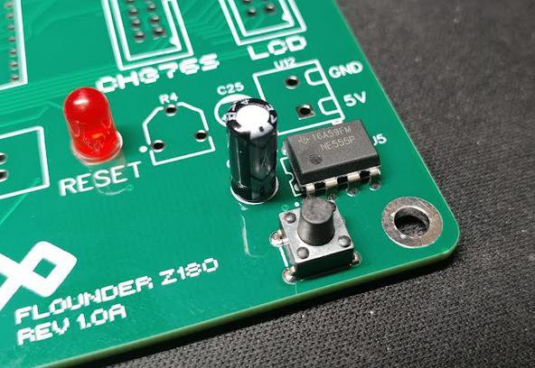
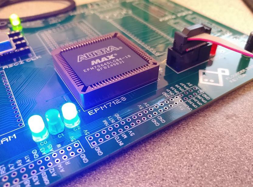
Next up is the 555 power-on reset. I've used this exact circuit in other projects, so I didn't expect too many issues. After soldering (the resistors are SMD parts on the back of the board), a quick test shows it's working as expected.In the first Flounder prototype, I used the 44-pin version of the EPM7064 CPLD, but on this PCB, I opted for the 84-pin package. I was a little nervous I missed something obvious in the transition, but happily, that was not the the case. The CPLD has two clock inputs: the PHI output from the Z180 and a second oscillator directly connected. Since the Z180 is not yet installed, I soldered in the secondary oscillator and the CPLD along with its debug LEDs and programming header.
Quartus detected the CPLD right away and I was able to program a simple counter/blinker circuit to test the clock input and LEDs. The CPLD is alive!
It's a bit hard to test the Z180 without the ROM and RAM also hooked up, but to reduce the number of variables, I connected just the CPU at first. I updated the CPLD program to output all zeros on the data bus and I powered on the system. On the oscilloscope, I could see that PHI was at half the frequency of the clock oscillator and there was a lot of activity on the address bus. The Z180 is happily executing NOPs. Not much else to do now but hook up the memory and a serial port and see what happens.
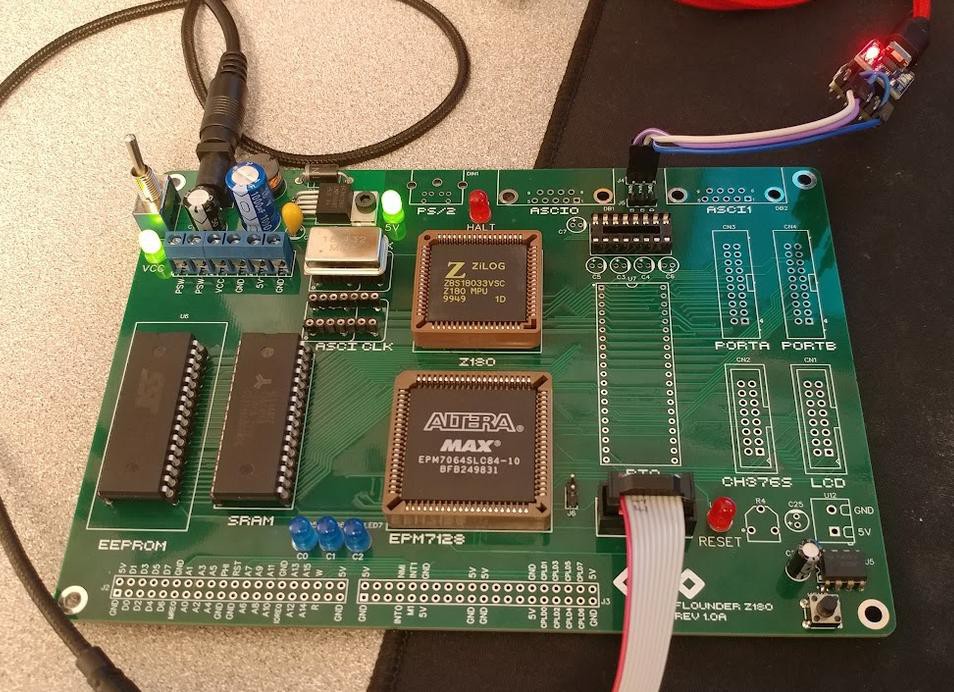
After some inevitable difficulties updating the decoder Verilog for the larger CPLD, I installed the ROM and RAM and connected a serial port.The serial monitor is running! Very nice. With the CPU, memory, and serial port working, everything else feels like a bonus.
I connected the MAX3232 and the DB-9 plug to test that the monitor still runs over RS-232. All good. Finally, I added the PS/2 connector and verified I'm still able to decode key presses.
Still left to go: the PIO and the port A/B connectors, the LCD display, and the CH376S USB adapter.
It's great to have the core functions of the system working. I've got one more week in the Retro Challenge to finish validating this board. I'd like to cleanup some of the software in that time as well.
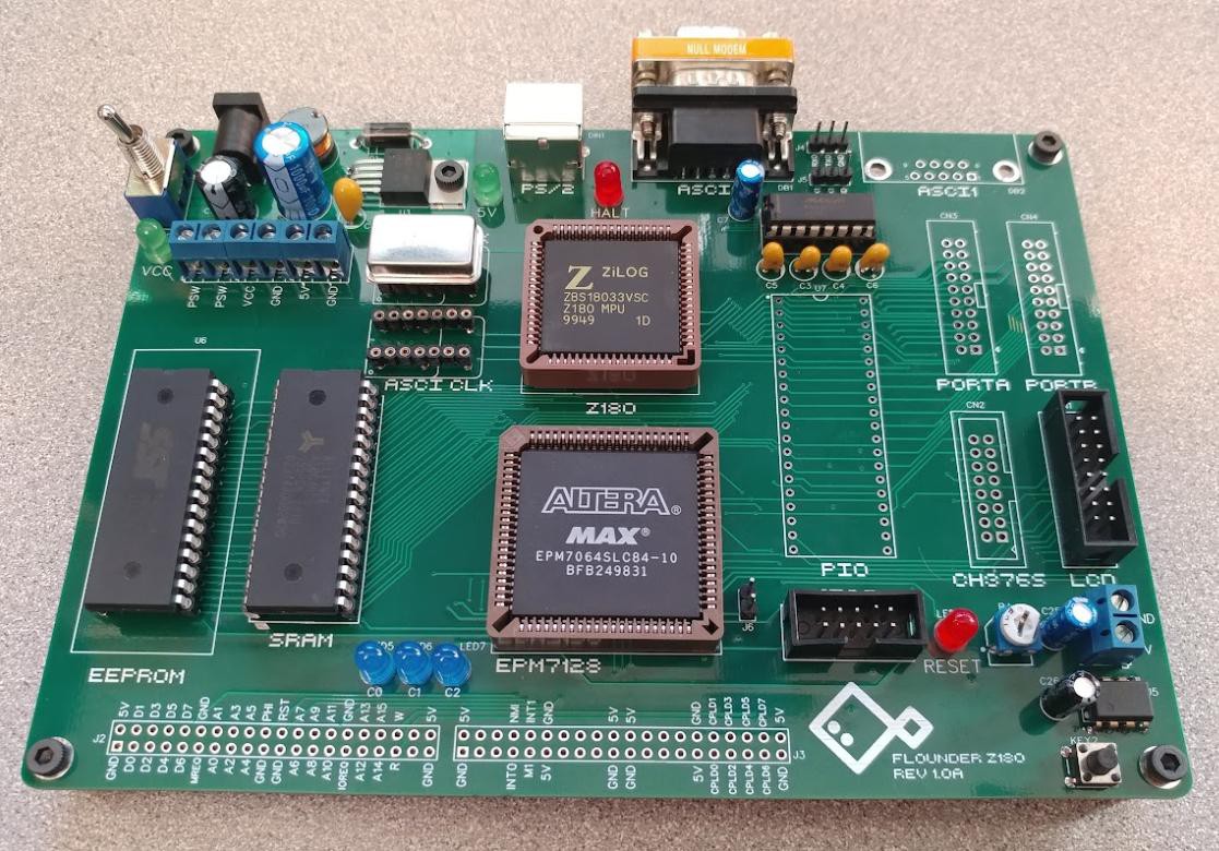
The board as it stands now: -
RC 2022/10 Day 15: In Production
10/15/2022 at 17:47 • 0 commentsThe first prototype of Flounder has been submitted for manufacturing. Now we wait... Fingers crossed that I didn't miss anything obvious in the design or PCB layout.
I've put the Gerber files and schematics in the Github project: https://github.com/crmaykish/flounder-z180/tree/main/releases/rev1.0a
The build should take about four days and shipping is about a week. Ideally, that leaves me five or six days at the end of the month to bring up the board. In the meantime, there's no shortage of software work that can be done, but I think a few days break is warranted.
-
RC 2022/10 Day 13-14: Rev 1.0 is routed!
10/15/2022 at 04:09 • 0 comments![]()
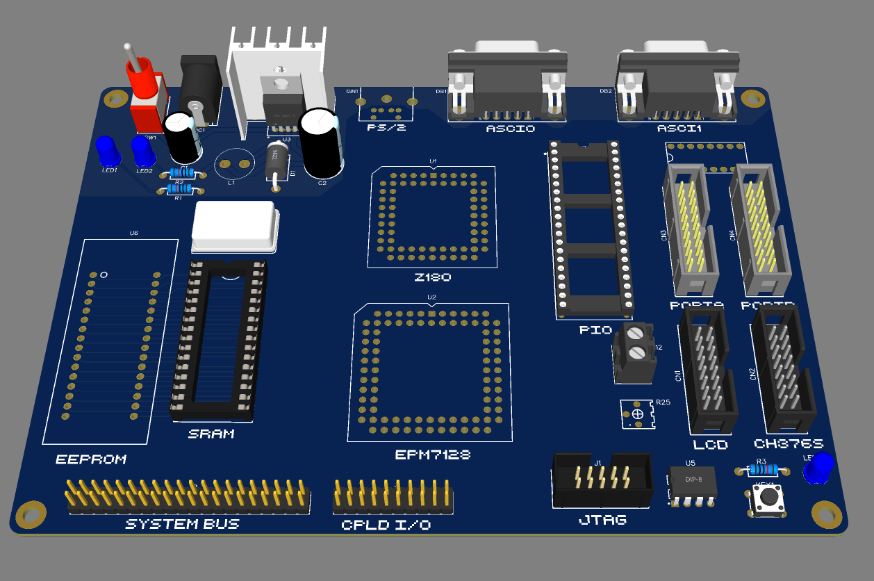
A few design tweaks and many hours of routing later, Flounder Rev 1.0A is ready for manufacturing. Other than rearranging some of the connectors, the most significant changes are the reworked power supply. I removed the heatsink and mounted the regulator to the board directly. I also added in screw terminals for voltage in, voltage out, and the power switch. When I build a case for this board, I'll need dedicated connectors for those.
At first I was debating trying to get away with a two-layer PCB, but I quickly decided against it. I think there would have been room to route the power and ground cleanly enough, but the price difference to upgrade to a four-layer board is about $30. The ease of routing and the better signal integrity seems worth it. The one "compromise" I made was using 1206 SMD parts for all of the resistors and decoupling capacitors. They're all on the back of the board.
Although there are a few signals that I did not use in this design, I made sure not to short anything directly to ground or 5v. Unused outputs were left unconnected and unused inputs were all connected to the appropriate level via a pullup or pulldown resistor. I've made been lazy about that in the past. Shorting signals directly to 5v or ground makes it much more annoying to bodge in a fix.
Time to sleep and review the design tomorrow. If I don't find any issues in the morning, I'll be sending the board off for manufacturing.
-
RC 2022/10 Day 11-12: Start of a PCB
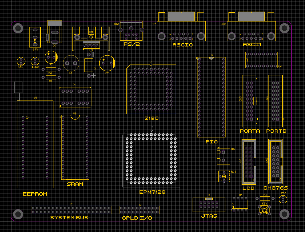
10/13/2022 at 03:26 • 2 commentsAfter double-checking all of my connections and meticulously translating my prototype boards into CAD, I'm ready to start laying out a PCB. I've roughed out the layout, taking care to position the power and rear I/O with the hope of fitting this board into a case eventually. The rest of the board is stubbed out with the approximate position of the components.
![]()
The biggest difference between this PCB and my prototype is the larger CPLD. With just the bare minimum prototype hardware, I was using every single available I/O pin on the 44-pin CPLD. I've upgraded to the 84-pin variant. I'll get a bit more breathing room in my hardware design this way plus there's a potential for more hardware expansion/prototyping opportunities.
You can see I've broken out a ton of I/O on the top and right side of the board: PS/2, serial, parallel, and dedicated headers for the LCD and CH386S module. The address/data/control lines will be available on the system bus header, and any unused CPLD I/O will go to its own header as well.
I haven't routed much of this yet. I'm not really looking forward to dealing with the two big PLCC chips in the center, but if I can get that connected cleanly, the rest of the I/O routing should be straightforward.
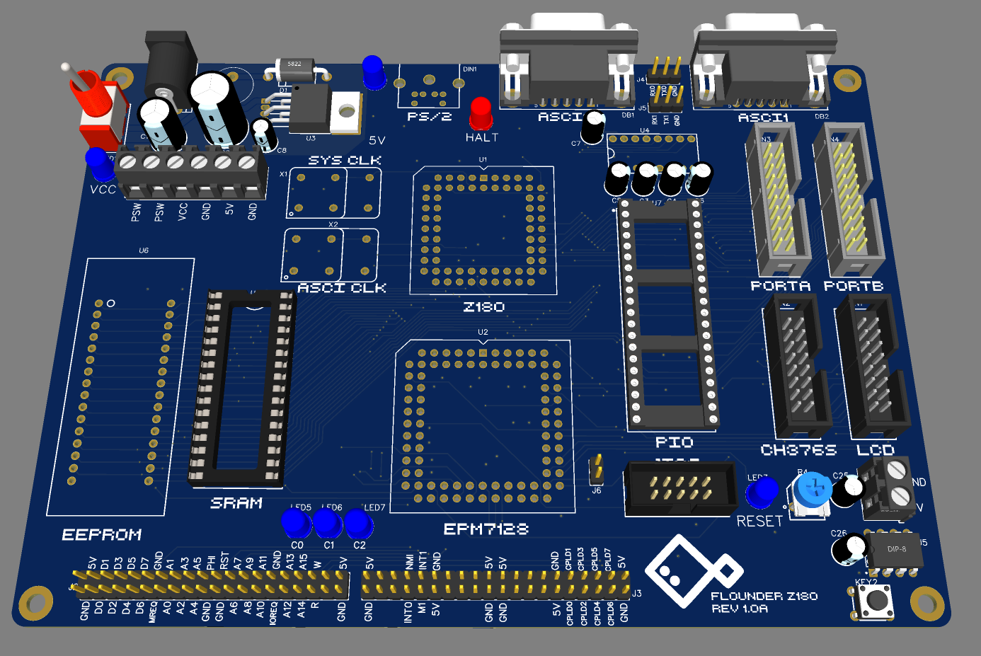
Here's a messy render of the board as it stands currently:
![]()
-
RC 2022/10 Day 9-10: Dealing with Flaky Hardware
10/11/2022 at 00:47 • 0 commentsThe good news first: I'm finally starting to grasp the z88dk configuration. I've managed to remove all of the hacky nonsense in my code to work around my lack of understanding of the proper way to do things. Without relying on any custom assembly or my own CRT code, I've got vectored interrupts running as expected. It turns out it's just much easier to store the vector table in RAM than in ROM (I should have learned that lesson from the 68000). Here's the command I'm using to build my monitor program:
zcc -v +z180 -startup=1 -SO3 -clib=sdcc_iy -g -m -o monitor -create-app \
    monitor.c \
    flounder.c \
    ps2.c \
    -pragma-define:CRT_INTERRUPT_MODE=2 \
    -pragma-define:CRT_ENABLE_EIDI=0x13 \
    -pragma-define:CRT_ORG_VECTOR_TABLE=0xFB00 \
    -pragma-define:CRT_ORG_CODE=0 \
    -pragma-define:CRT_INCLUDE_PREAMBLE=0
To summarize: this is building my code against the embedded Z180 CPU target and associated libraries and building a ROM image. It's also taking care of setting the interrupt mode to 2 (vectored interrupts), enabling interrupts at the appropriate time and setting up the vector table high up in RAM at $F800.
The bad news is that it took me many hours of chasing my tail to get to this simple-looking solution. I ended up re-implementing all of the interrupt handling and vector table setup by hand to prove to myself that the software was working as expected. It was. I was still having horrible stability issues when interrupts were on and the LCD display was connected. If I removed either of those pieces, things seemed a little better. I spent some time debugging the address decoder logic and the display controller timing looking for bus conflicts or other issues. Everything seemed fine. After many hours of this, I rearranged some of the boards on the backplane and things were magically stable...
I'm not planning to use a backplane in the PCB design, so this is not the end of the world, but it's a good reminder never to trust the hardware. I'm not 100% sure if the problem is due to reflections and noise on the backplane or if I need to add some bus transceivers between the CPU and everything else. All of my peripherals are low current modern CMOS chips so I'm crossing my fingers that this is just a problem with the backplane and my miles of messy jumper wires.
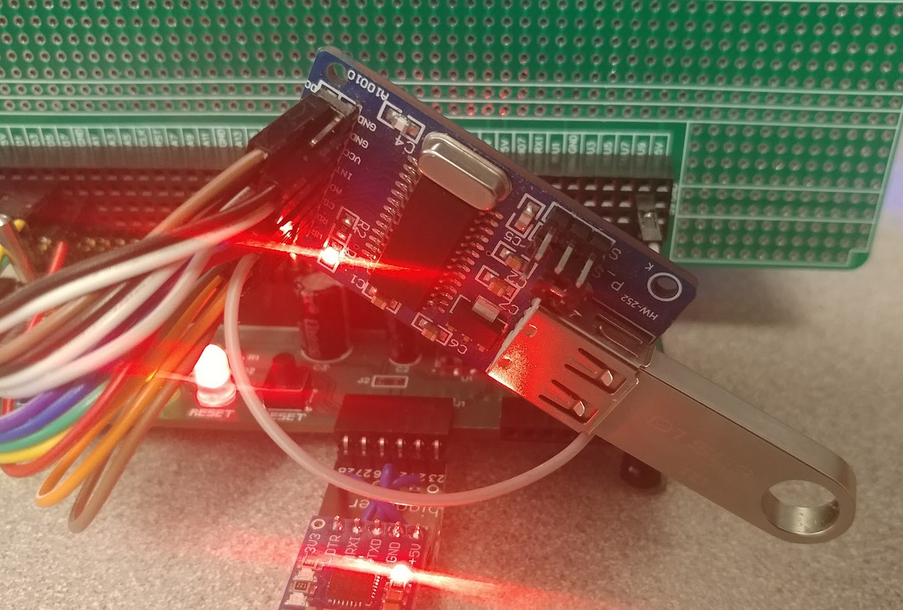
Once I did some cleanup of the code and convinced myself the system was stable enough to continue, I moved on to wiring up the CH376S. Like the LCD display, this chip is designed with Z80-style 8-bit parallel buses in mind and the pins all map one-to-one. I have some experience using the CH376S on my other homebrew systems, so rather than build all of the software out for the Z180 now, I just want to see some signs of life for now.
My goal is still to get a working version of this computer on a single PCB by the end of the Retro Challenge. To make that schedule work, I'm going to stub out all of the hardware and get it to a proof-of-concept state and then move on to PCB design. While I'm waiting for the PCB to be manufactured and shipped, I'll have some time to work on the software.
Anyway, here's my proof-of-concept testing for the CH376S:
** Flounder Z180 System Monitor **

> ipoke A001 05

> ipoke A001 15

> ipoke A000 05

> ipoke A001 06

> ipoke A000 55

> ipeek A000
AA
Again I was able to use the monitor to communicate manually with the chip. I got enough information to show that the wiring is correct and the communication is working as expected. This series of pokes resets the CH376S and sets it to USB host mode. The final command 0x06 and the following data value 0x55 maps to the CMD_CHECK_EXIST command. It responds with the binary-inverted value that you send it, in this case 0x55 -> 0xAA.
![]()
That red LED is off by default, so when it turns on, it shows that the module has initialized correctly following the reset commands.
With that, my initial hardware requirements check list for the first version of Flounder is almost complete. The only other things I'd like to quickly prove out are the MAX232 circuit and connector pin-outs and maybe experiment a little with the power supply / reset circuit.
The PCB design will likely take a few days for a board as complex as this one and the manufacturers will take a week to get the boards to me, so I should have another week before the end of the challenge to bring up the boards. It's a tight schedule, but I think it's doable.
-
RC 2022/10 Day 8: 4004 LCD Display
10/09/2022 at 01:25 • 0 commentsI'll start with the most exciting update. I upgraded the 1602 LCD to the planned 4004:
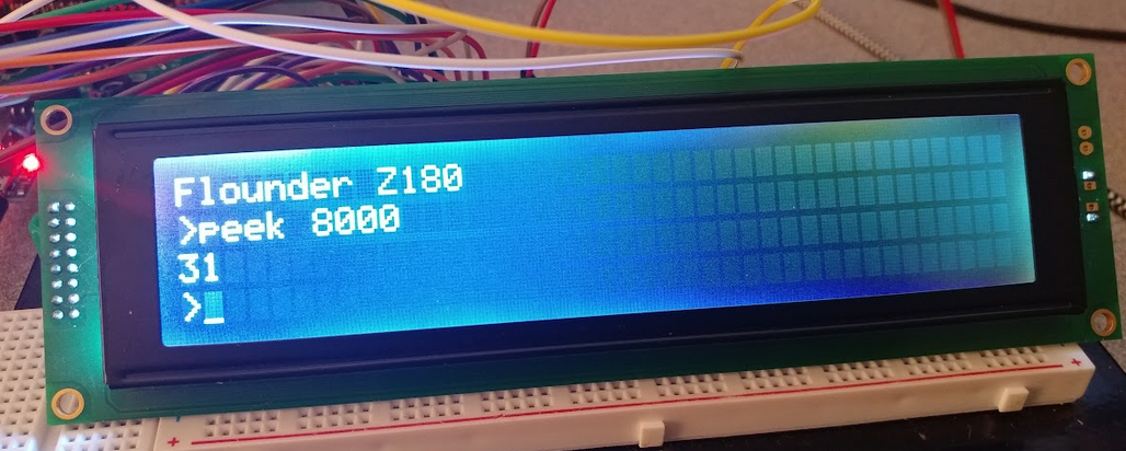
![]()
As you can see in the picture, I also have pieces of my monitor input loop displaying on the LCD. Going from the 1602 to the 4004 doesn't change a lot on the hardware side aside from the extra enable pin. This display is actually set up as two 2x20 panels stuck together. All of the data and control lines for both segments are wired together except for the chip-select line. I had to add another output from the address decoder CPLD and map the bottom two rows as a separate I/O device.
The big drawback to this configuration is that you have to keep track of the state of each panel and update them independently to give the illusion that it is in fact one continuous display. I tried to hide this behind some basic putc()- and puts()-type functions because I wanted smooth vertical scrolling as new lines come in. It's transparent to the monitor program, but the internals are a bit messy. The user experience seems pretty good though. When a cursor is on the last row and a new line comes in, the bottom three rows shift up one and the whole screen redraws. I was afraid this would be noticeably slow, but it's instantaneous. I'll have to upload a video of this in action.
In other news, I made some more progress in understanding z88dk. I was able to utilize the embedded Z180 CRT code instead of having to hack together my own, but in the process, I broke my interrupt support. Back to the docs to figure out the "official" way to implement ISRs.
-
RC 2022/10 Day 7: 1602 LCD Display
10/08/2022 at 01:26 • 0 commentsFirst week of Retro Challenge is in the bag! Happy to say I've got at least some of a functioning computer, albeit missing a lot of the project goals.
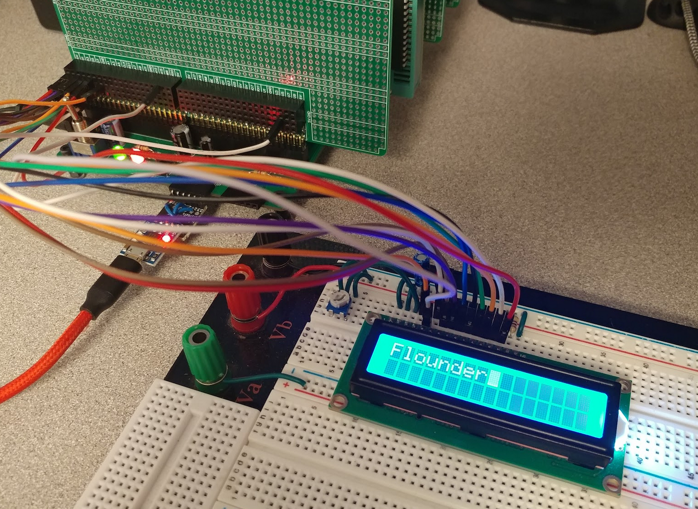
Today I hooked up a 1602 LCD display as a stepping stone to the 4004 I'd like to end up with. The 4004 is really two smaller displays smashed together, so there's a little complexity to make them behave as one. I wanted to prove out the circuit with the smallest LCD display I had.
The connections are about as simple as possible. Data bus connects to the 8 data pins, chip-select (active high) goes to a decoder pin on the CPLD (mapped to 0x6000 in I/O space), register select goes to A0. I hooked up the R/W pin on the display directly to the WR pin of the Z180. I've seen reports of this not working for some people. Instead, they inverted the RD signal and passed that in instead. So far, I've had no issues using the WR pin, but I'll do some testing at different clock speeds to see if there's any timing issues.
One nice thing that made connecting up this display easier was having access to I/O peek and poke commands in the system monitor. I was able to prove the display was wired up properly without writing a single line of code, instead I could just poke commands and data into the LCD until I was sure the circuit was correct. I did wrap up these commands into some C functions eventually. Once I adapt the monitor code to use this display as output and the PS/2 keyboard as input, I'll technically have a standalone computer. Pretty cool :-)
![]()
Flounder Z180 Computer
Standalone single-board computer based on the Zilog Z180 CPU
 Colin M
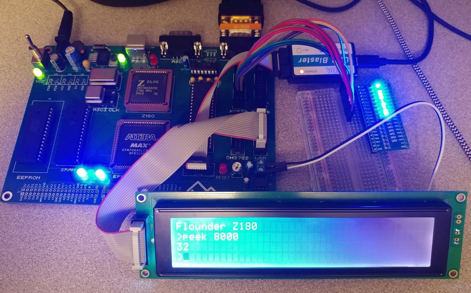
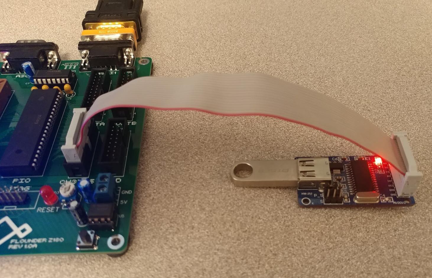 Overall, I couldn't be happier with the first revision of this PCB. There are a few minor tweaks to make for the next iteration, but there's no rush on that. I have feature parity with my prototype and nothing is blocking me from spending some time on the software side to get Flounder doing something fun. I've only got a few more days in the Retro Challenge and I'd like to have a cool demo to show off instead of just a serial monitor program.
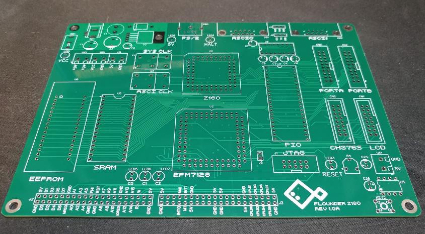 There are no obvious manufacturing issues or design problems that I can see, so it's time to start building. First step is the regulator circuit. It's a simple LM2576 buck converter stepping the 12v input down to 5v.
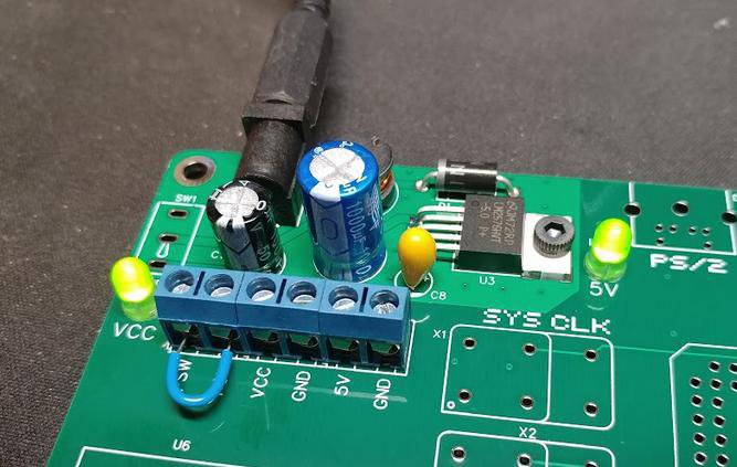 Nothing blew up and the LEDs come on. Multi-meter shows a solid 5v on the output. Good start.
 In the first Flounder prototype, I used the 44-pin version of the EPM7064 CPLD, but on this PCB, I opted for the 84-pin package. I was a little nervous I missed something obvious in the transition, but happily, that was not the the case. The CPLD has two clock inputs: the PHI output from the Z180 and a second oscillator directly connected. Since the Z180 is not yet installed, I soldered in the secondary oscillator and the CPLD along with its debug LEDs and programming header.
 Quartus detected the CPLD right away and I was able to program a simple counter/blinker circuit to test the clock input and LEDs. The CPLD is alive!
 The serial monitor is running! Very nice. With the CPU, memory, and serial port working, everything else feels like a bonus.