Maksim Surguy
-
First test of complete 7 Segment display
12/25/2016 at 10:42 • 0 commentsI had a preprogrammed NodeMCU (ESP8266) chip laying around with a FastLED library and test patterns already there.
At this point, connecting Pin 2 to the Data Input of my PCB and connecting power pins should work unless I fry something.
Here's what happened after I connected everything together:
And then I was able to take a video of the display in its full glory, still running test patterns:
It works in a beautiful way that is hard to describe or convey even with video, I think you have to see it in person to get the full effect.
Next steps: optimizing the 3D model and PCB, making this modular and making 2 or 3 different sizes of the display!
-
Soldering components
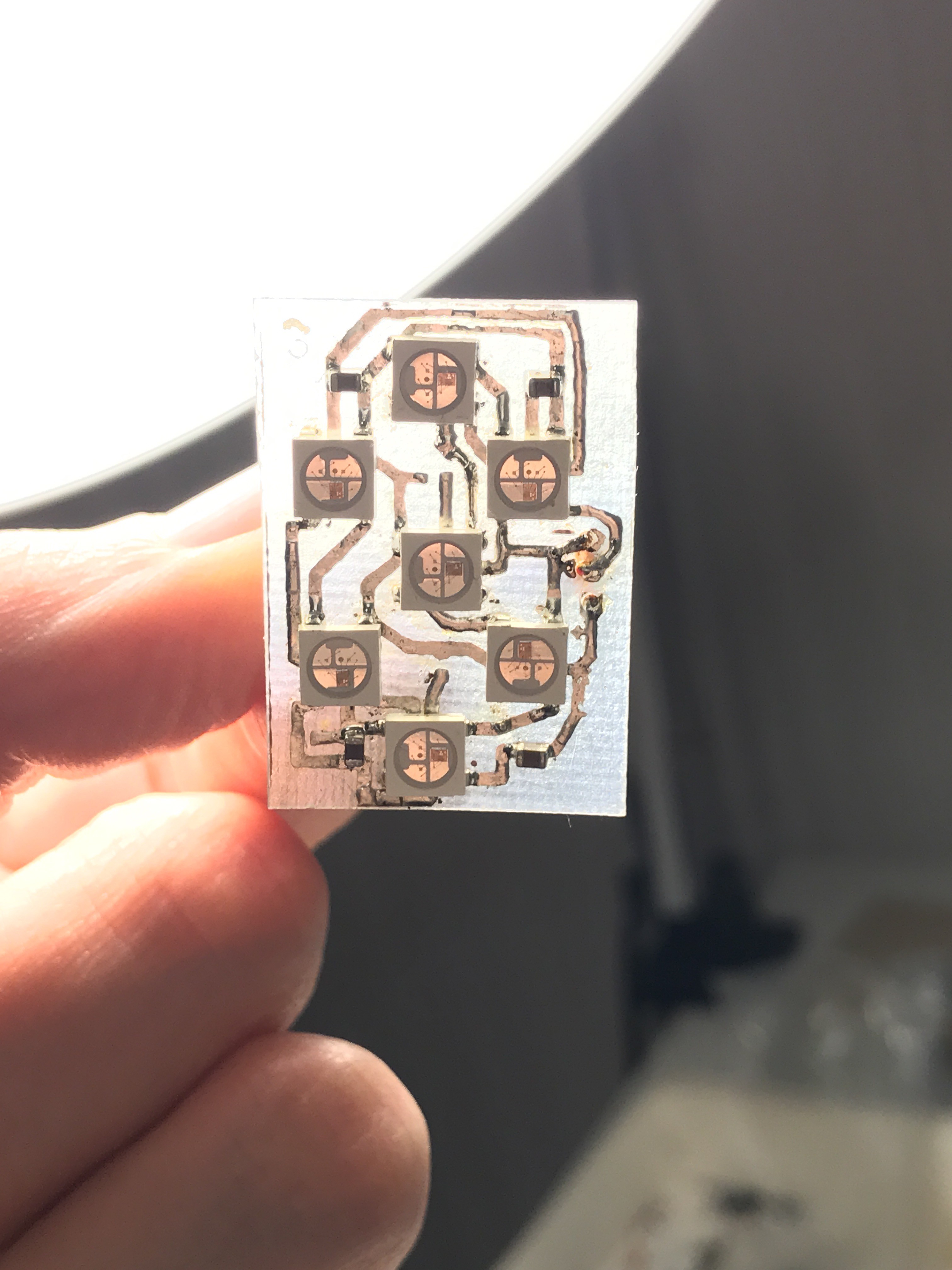
12/25/2016 at 10:31 • 0 commentsAfter the circuit board was designed, printed on photo paper, transferred onto copper and etched, it was a quick process to solder 7 LEDs onto it. Soldering took about 15 minutes start to finish and I imagine this could be done much faster if you can use a reflow oven instead of hand soldering each component.
I was impatient and soldered only 4 capacitors instead of 7 because I knew that this first prototype won't be chained together with other displays.
Here is how the populated circuit board looks like:
![]()
The lesson learned here was to create bigger pads for the Neopixels which will be taken care of in the next iteration of the PCB design.
I don't know if I need bypass capacitor on each and every LED or if putting one 10uf cap per 7 Segments would suffice so if you know the answer to that question, please let me know!
-
Designing the schematics and the circuit board
12/25/2016 at 10:20 • 0 commentsNow that I have a proof of concept 3D printed model of the display, it is time to design a circuit board for 7 WS2812B LEDs that will light up the numbers on the display.
This time I decided to use KiCad as an opportunity to learn proper circuit board building and after the schematics design is finished, I will finally put my new laser printer that I got on Cyber Monday to a good use to create a Printed Circuit Board (hint: toner transfer method)!
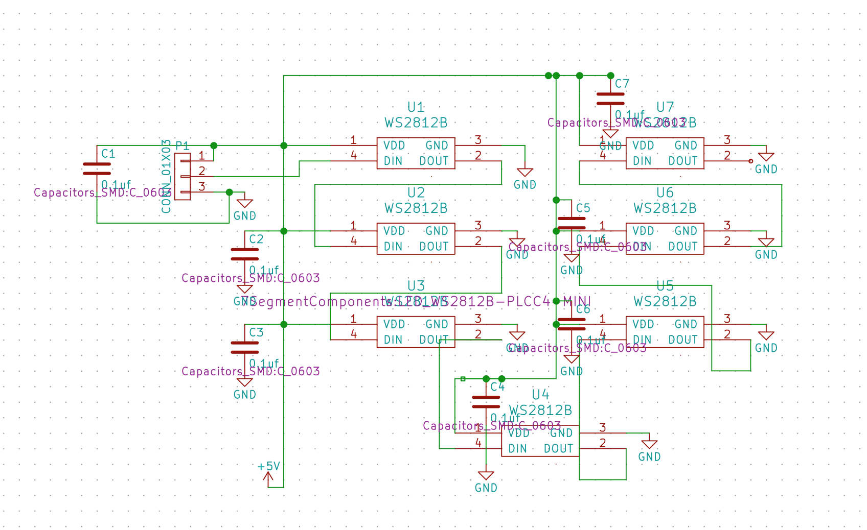
The schematics design for this display is very simple and consist of only two kinds of components: WS2812B LEDs and capacitors. Each LED of this type has input and output pin so the series of LEDs need to be put together in a particular way: data output of one LED needs to feed into data input of another LED.
Here's the design of the schematics in KiCad's EESchema before it was exported to PCBNew:
![]()
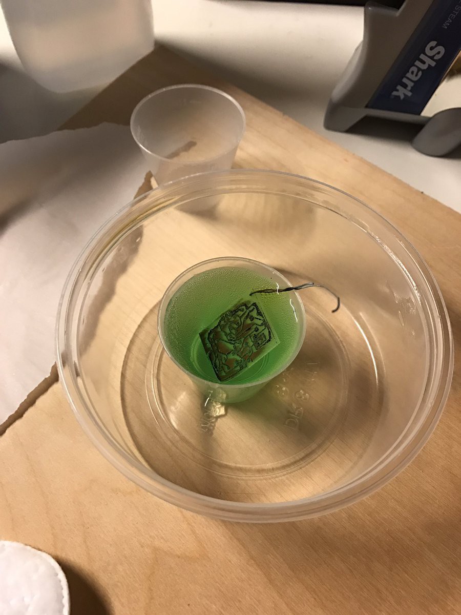
In PCBNew, I placed the components at distances that correspond to my 3D printed model, then ran Freerouter to create a layout with minimum traces and no through hole connections. I then had to manually adjust a few pads and placements in order to use space efficiently. After about 3 tries of printing the circuit board and etching it (picture below), I was able to make one that worked.
![]()
I've attached the circuit board schematics and the PCB design in Files section of this project.
Neosegment - 7 Segment Display made with Neopixels
Creating a custom 7 segment display that can be driven with Arduino opens up some new possibilities.