Real Solar Cars
-
Additional Considerations
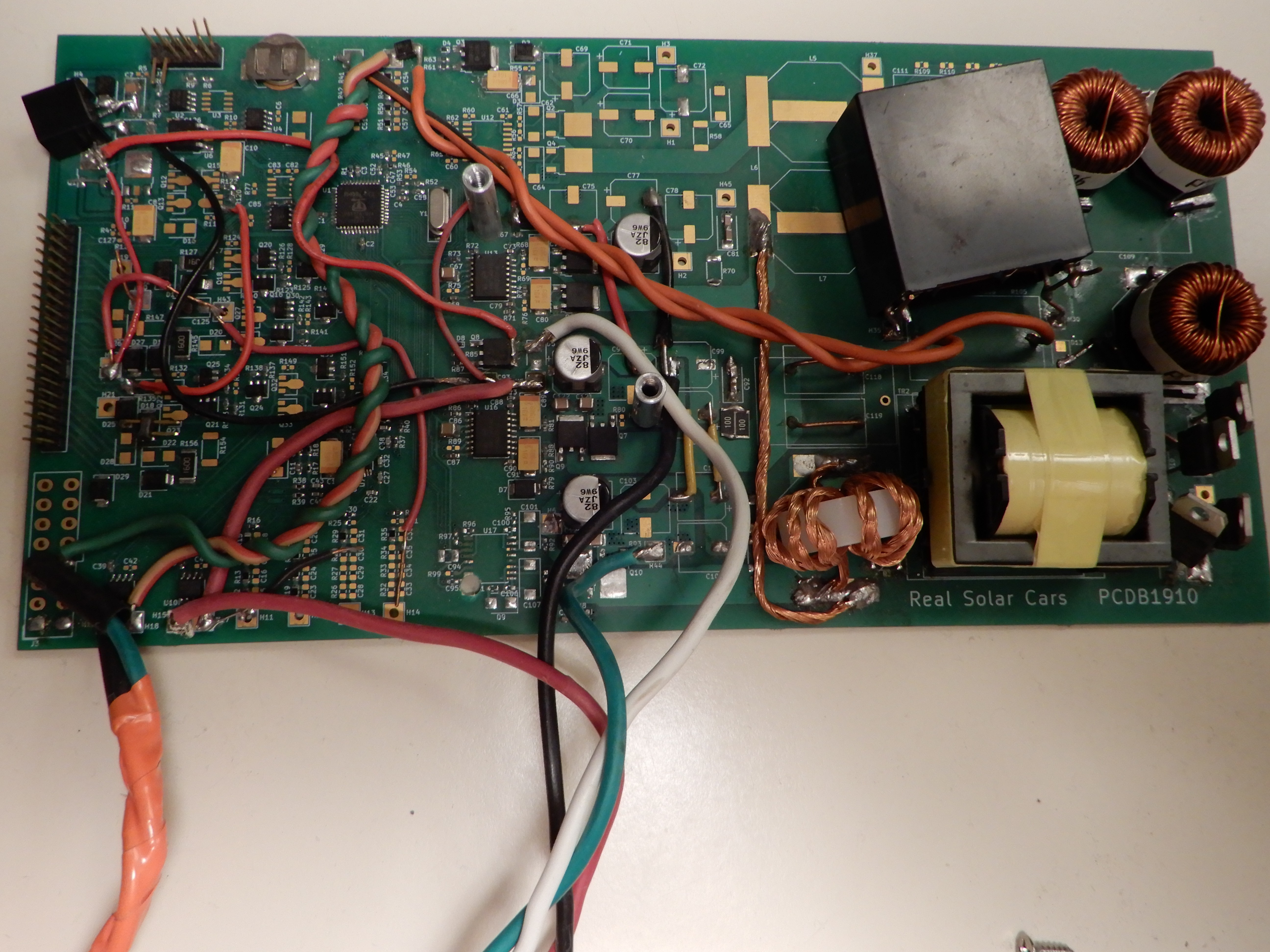
10/21/2022 at 04:42 • 0 commentsThe PCDB1910 met most of the minimum requirements with copious jumper wires installed. Most importantly, it proved that it was possible to DC charge the vehicle without damage or constantly setting the “check engine” light. My experience with this board led to a list of improvements for the next revision.
![]()
- Maximum power point tracking is desirable for all solar electric systems. Well, Electrodacus might disagree. But with a small vehicle mounted solar array, the vehicle will consume all the power it can generate. I eventually added MPPT to the software for the first board revision after running without it for a while. It is particularly frustrating to see reduced charge power at low state of charge.
- 12v auxiliary output. 12v charge controllers are a common off the shelf item. But the marginal cost of adding a 12v output to the main board would surely be less than a separate 12v charger. There is also the issue of running two MPPT controllers off one solar array. They may conflict. Many charge controllers expect the solar negative connection to be floating with respect to the battery negative. I was lucky to find a charge controller that worked in this situation. The first board revision using the Propeller 1 was intended to have this feature but it did not have enough current sensors or processor cores.
- 12v adjustable output. The Chevy Volt operates its factory DC-DC converter (replaces the alternator) at a reduced voltage sometimes to save power. The off-the-shelf charge controller I used with the first board revision output a constant 14.4v due to the load of the contactors and battery management system. Reducing this to 13.8v or below may save some energy.
- Energy logging. It’s important to monitor the amount of energy collected to detect problems This data will also be useful for promoting this unusual solar car system. The first board revision used the battery backed RAM of a DS1307 to maintain a kilowatt-hour count. Now, I use a Raspberry Pi that logs data from the solar charger board as well as the vehicle’s battery management system. It even uploads to the realsolarcars.com website.
- Automatic day/night switching sounds trivial at first. But when it comes to programming the microcontroller, it becomes complicated. Most charge controllers can cycle on and off at dawn without issue. That is a big issue when charging a high voltage drive battery. The high voltage charger should be turned on only when there is enough available power to overcome the overhead of the contactors and battery management system. And the number of on/off cycles should be minimized because that involves closing the contactors and a high voltage precharge.
- Contactor coil economizer. Contactors require a certain amount of voltage to close. But once closed, they will stay closed with much less voltage. If the voltage can be reduced during contactor operation some power can be saved. The Chevy Volt does not economize the contactors. This may be a bad idea while driving; the vibration could cause the contactor to open unexpectedly. And there is not much motivation to economize the contactors when charging from grid power.
- Electromagnetic interference. Since the solar panels are mounted extremely close to the radio antenna, any electromagnetic interference from a solar charger could have a significant impact on radio reception.
- Function as a logic analyzer for development work. The best way to figure out the how to operate the vehicle’s contactors is to put the vehicle in different states and observe what it does.
- Designed for an enclosure. Since dust and moisture is common in the automotive environment an enclosure with an IP68 rating would be ideal. However, the space available in the vehicle is fairly restricted. Also, the board needs to dissipate heat well. So a plastic enclosure would not be as desirable. Most power inverters use an extruded aluminum enclosure for this reason. As a compromise I designed the board to fit into an IP66 rated Bud EXN-23366 enclosure.
-
Charge Controller Minimum Requirements
10/07/2022 at 03:27 • 0 commentsOne it was clear that I needed a custom step-up charge controller for my solar car project, I needed to plan out the design. Let’s address the MUST HAVE requirements first:
- Output voltage regulation is one important safeguard against overcharging the lithium-ion battery. Voltage regulation is also necessary to prevent damage to other vehicle electronic should the contactors open unexpectedly for any reason.
- Isolated high voltage output. While solar panels are commonly connected in arrays capable of generating 400v DC, it would be best practice to have the solar panels isolated from the high voltage drive battery. This proved to be a minor burden. The standard non-isolated step-up converter is not well suited for a 10:1 voltage ratio anyway. I used a full bridge converter which provided the necessary voltage gain and isolated output.
- Contactor control output. It seemed much easier to access the battery pack using the existing contactors instead of opening the pack and making a new connection inside. More on this in another update, or check the Real Solar Cars youtube channel. It would not work to simply turn the car on to charge. The Chevy Volt uses about 250w at idle. The 420w array on the car usually collects about 200w in realistic conditions. In any case, 250w is a lot of overhead. To minimize the overhead, it’s necessary to charge the car with all systems off except the contactors and battery management system. The battery management system on the Chevy Volt is enabled by a 12v signal on the same connector as the contactor signals.
- A CAN bus interface is needed to receive data from the vehicle’s factory battery management system.
The automotive environment adds unique challenges that are not often encountered in DIY projects:
- High and low temperatures were addressed by choosing automotive grade parts when possible. I also spent a lot of effort making the board operate efficiently to minimize the temperature rise. Multiple temperature sensors help ensure that the board can shut down before reaching damaging temperatures.
- Moisture may eventually lead to corrosion. This is likely to affect connectors first. So no unnecessary connectors. It may be desireable to apply conformal coat to the circuit board.
- Vibration is another reason to avoid unnecessary connectors.
- Serviceability. The circuit board needs to be removable for repairs or modifications. I ended up using a 40 pin IDE connector for this.
- Safety critical. It’s not likely that rouge data on the Chevy Volt high voltage management CAN bus would cause a collision. This bus is separate from the main CAN bus. What is more likely is getting stranded at the side of the road. The solar charging board should not impede any important vehicle operations. It must be possible to switch off the solar charger board and have the vehicle operate as before. This was accomplished by adding diodes which allow the vehicle’s contactor control signals to pass through. In the event that these diodes interfere with vehicle operation, the solar charger can be quickly disconnected and replaced with a bypass board. The bypass board connects the input signals directly to the output signals.
TL;DR
Charger board minimum required features:
- 400v DC regulated and programmable output voltage.
- 400v DC output to be isolated from solar panels and vehicle chassis.
- CAN bus and contactor control outputs for the vehicle interface.
Charger board design guidance:
- All important functionality incorporated on a single circuit board.
- Preference for vibration resistant SMT parts when possible.
- A single board with mostly SMT parts is preferable for mass manufacturing as well.
System design guidance:
- A connector to allow the solar charger to be quickly replaced with a bypass board.
- Pass-through diodes mounted on the vehicle side of the interface connector.
- A high quality highly flexible interface cable rated for water and oil.
The PCDB1910 board was designed to meet these minimum feature requirements.
-
There's more than one way to ... build a solar car.
10/04/2022 at 06:38 • 0 comments- The easiest way is to add an off-grid solar system to the trunk. Many people have done this. It requires no electrical modifications to the vehicle. There are many downsides.
- A vehicle is a hostile environment for lithium batteries and inverters. Adding a cooling system adds more cost and parasitic energy losses.
- The added batteries add weight to the vehicle. Although 12 kg for a single LiFePO4 shouldn't matter much. The additional energy on board should more than counteract the range loss.
- Battery degradation ruins the economics of solar charging. Even a cheap LiFePO4 that might last 4000 cycles adds $0.06 per kwh.
- The charging cable must be plugged into the vehicle's J1772 port. Charging while driving is not permitted.
- The overall efficiency of this setup is hurt by converting low voltage DC into 120v AC and then converting the 120v AC into 400v DC. Also, the MPPT charge controller is an additional conversion from 17v to 13v for the battery charging.
- Try to use existing vehicle hardware and hack it to work for solar charging. The on-board charger is simply a large switch-mode power supply. So in addition to AC power it should be able to charge from 100-300v DC. In a test, the Chevy Volt did charge from 120v DC. The charger reports RMS voltage over CAN bus. The rest of the car has no way of knowing that I fed it DC.
- The vehicle's on-board charger typically has a maximum power of 3000-6000w. The efficiency of these chargers at 50-300w is likely to be low.
- This method might also require plugging into the vehicle's J1772 port, preventing charging while driving. But maybe that interlock could be hacked around?
- The J1772 standard only allows current down to 6 amps. Maybe the voltage could be reduced to 100v and still charge. An array capable of producing 600w won't easily fit on the roof of a car. Efforts to reduce that charge current on the Chevy Volt were not successful. The charger output power is controlled by varying the output current. The Volt's computer adjusts the output current in order to control the AC input current. It is possible to override the output current via CAN bus. But then charging will soon stop when the computer notices a large difference between the commanded current and the measured current. This effort was abandoned due to concerns over point 2.1.
- The best way is to use purpose-built hardware. This is the only method that would be considered by OEM manufacturers like Sono Motors or Lightyear. A dedicated solar charger should be slightly more efficient than an AC charger since the power factor correction circuitry can be eliminated. Additionally it will be sized for efficient operation at the array's actual output.
- Connecting the new charger into an existing vehicle battery is its own can of worms. More on that in another update.
- There is not a lot of suitable electronics on the market to do this. Perhaps a microinverter could be hacked to function as the required DC to DC converter. Remember that microinverters have a complex anti-islanding algorithm that is necessary for safe grid connection. I felt that it was better to put effort into designing a custom converter. The GZF inverter modules seem ideal at first glance, but those have no output voltage regulation. With the high open circuit voltage of a solar panel the converter can output 900v. No way is that thing going on my daily driver! Also, they are wound for a 12v input, not the 17v maximum power point of a "12v" solar panel. And they operate at a fixed voltage ratio, preventing maximum power point tracking.
- A missed opportunity. If I was writing the J1772 specification I would add a mode for "solar charge." This would allow for cheap off-grid solar carports. Instead of specifying a current limit, this PWM frequency would instruct the vehicle to use a maximum power point tracking algorithm. The array would supply 100-300v DC that could be handled by the on-board charger. The rest of J1772 would work the same to ensure there is never live voltage on the connector when it's not plugged into a vehicle. If these were possible businesses might like them because of no need to run electric lines, and no recurring electricity expenses. They could be placed further from building so it would be less likely that people would just park there. And customers would feel good about charging with solar energy.
TL;DR
Making efficient use of the small solar array that can be mounted on a vehicle roof requires a purpose-built charge controller. There is little on the market meeting the requirements, so the charge controller needed to be built from scratch.
The J1772 AC charging port is not suitable for charging from a small solar array because it is designed to operate at 6 amps and above. If that could be overcome, the efficiency of a 3kw charger running at 10% power or less won't be that good. If it can't be overcome, it is necessary to add a storage battery which adds significant cost. Vehicle interlocks will prevent charging while driving.
- The easiest way is to add an off-grid solar system to the trunk. Many people have done this. It requires no electrical modifications to the vehicle. There are many downsides.
DC-DC Solar EV Charger
The key component to transform the solar car from a backyard science experiment to cost effective practical transportation.