Energy can neither be created nor destroyed, it can only change form. The source of earth's energy is the Sun. 71% of planet earth is water, which stores the Sun's energy. Water changes it's state into gas when hot and into a solid when cold. Water in the oceans vaporizes and evaporates on sunny days. Wind blows the vapors inland and rises up when it reaches land. This causes condensation, and this moisture turns into clouds. Precipitation occurs and the moisture falls as rain. Water runoff causes rivers to flow back to the oceans with minerals. Infiltration makes underground rivers flow to the ocean as well. Plankton and other plants start growing in the ocean. As well as plants grow on land. And the oceans and land evolve and fill with life. Bacteria evolved cleaning the ocean & keeping the balance. This balanced model is what we mimic with smart aquaponics

We start the model using a fish tank. In the tank, water and fish mimic the ocean. A gravel filled bed mimics the land. Recirculating water between the tank and grow-bed recreates the watercycle. Flora grows on gravel in the grow-bed. Bacteria colonizes the gravel, composting & filtering waste. Balance & sustainability is attained … until ...…Humans come into the picture. Humans farmed the land to create food . Nutrient runoff from human farms break the ocean's ecosytem. Similarly, our models break as soon as we add human elements to it. Smart aquaponics turn physical gardens into data... Mitigating many issues.
A functional overview of a smart aquaponics systems is shown below:
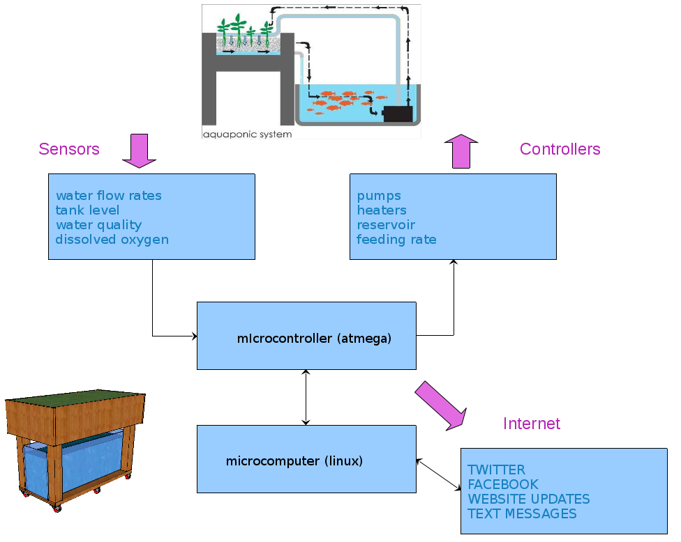
linux makes it very easy to control the arduino. rather than write scary firmware, we abstract the arduino code as much as possible so it only reads sensors and reports the values while accepting basic commands for flipping bits or voltages.. ie. sensor and relay driver logic only. all decisions are made using higher level code. eg. turn on lights and reports how bright they are. linux decides when or why or how to respond next. further, running openwrt on the $20 tp-link router replace like 50 shields. wifi, ntp, sdcards, webservers usb - video, audio, cellular links not to mention linux tools like crond, sshd, grep, awk, sed etc and fun ones like python, nodejs, javascript etc. oh is it also so cheap as compared to raspberry pi, beaglebone, dun etc. based solutions.
the micro controller part in this project is a standalone arduino compatible board using the atmega328. the function of this is to read sensors and drive actuators. it handles sensor logic and reports the status of the connected sensor through a json. string object in the serial line uart0. ie. turn on lights command is issued, light sensors reports lights are on.,
the linux computer sees the atmega part as a serial device, similar to a printer or keyboard connected to it. the linux micro uses the 'serial to network' ser2net utility to convert the atmega serial device into a network socket. so the sensors and relays on the atmega board can easily be accessed in linux using regular tcp/ip tools or as a device file /dev/ath0.
the data is then sent to a remote database application for data logging, monitoring, visualization, alerting, sharing and remote control.
Smart Controller Functional Overview
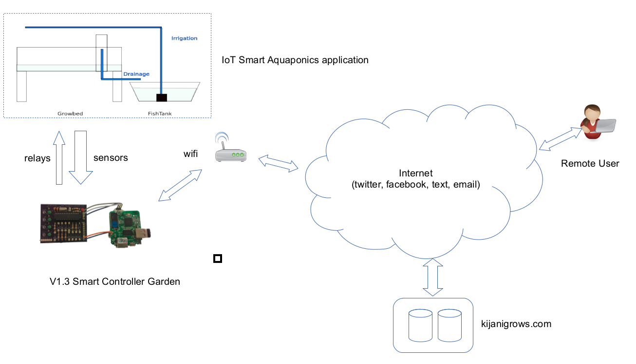 functional parts of the smart controller overview and some data flow is shown above. the two pcb boards show above are the atmega based smart controller board and the linux microcomputer board. the following stages will dig deeper into each individual block.
The Atemga Microcontroller Functional Block
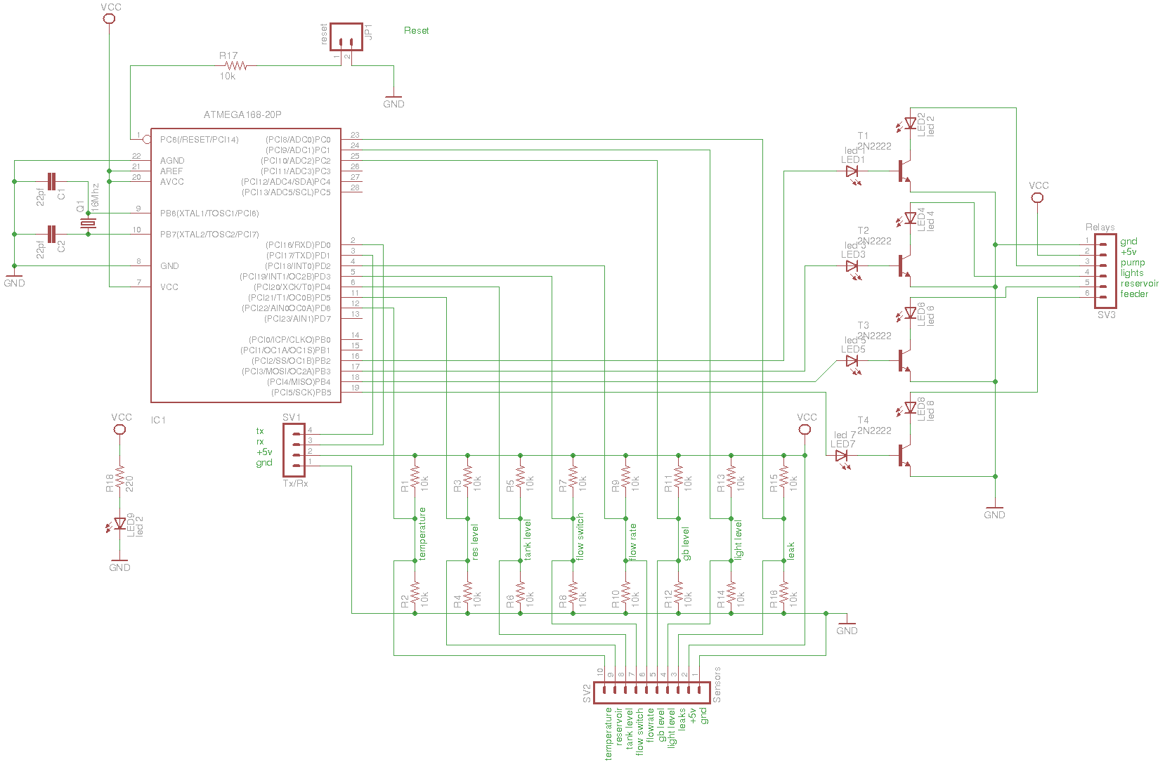
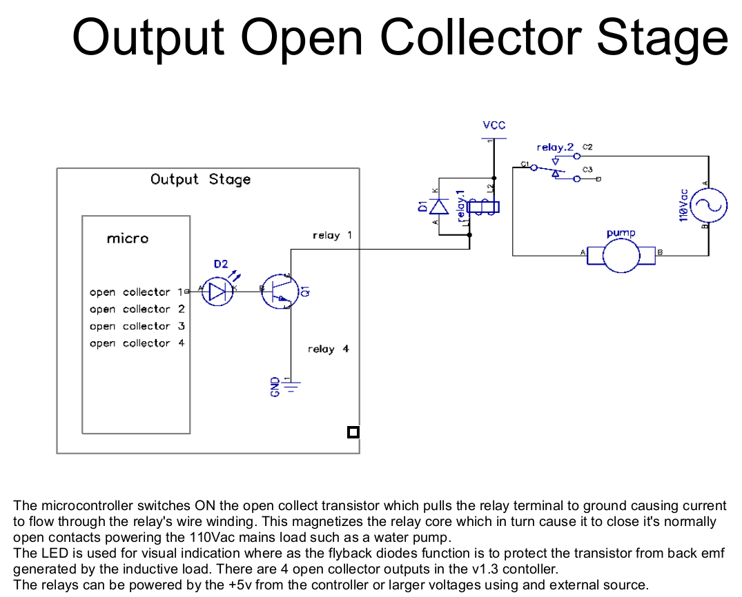
there are three main functional blocks, the atmega328 standalone brains, the input section consisting of pullup/pulldown resistors chains and an open collector output stage. there is also a uart section for connecting with the linux microcomputer and a power indicator section.


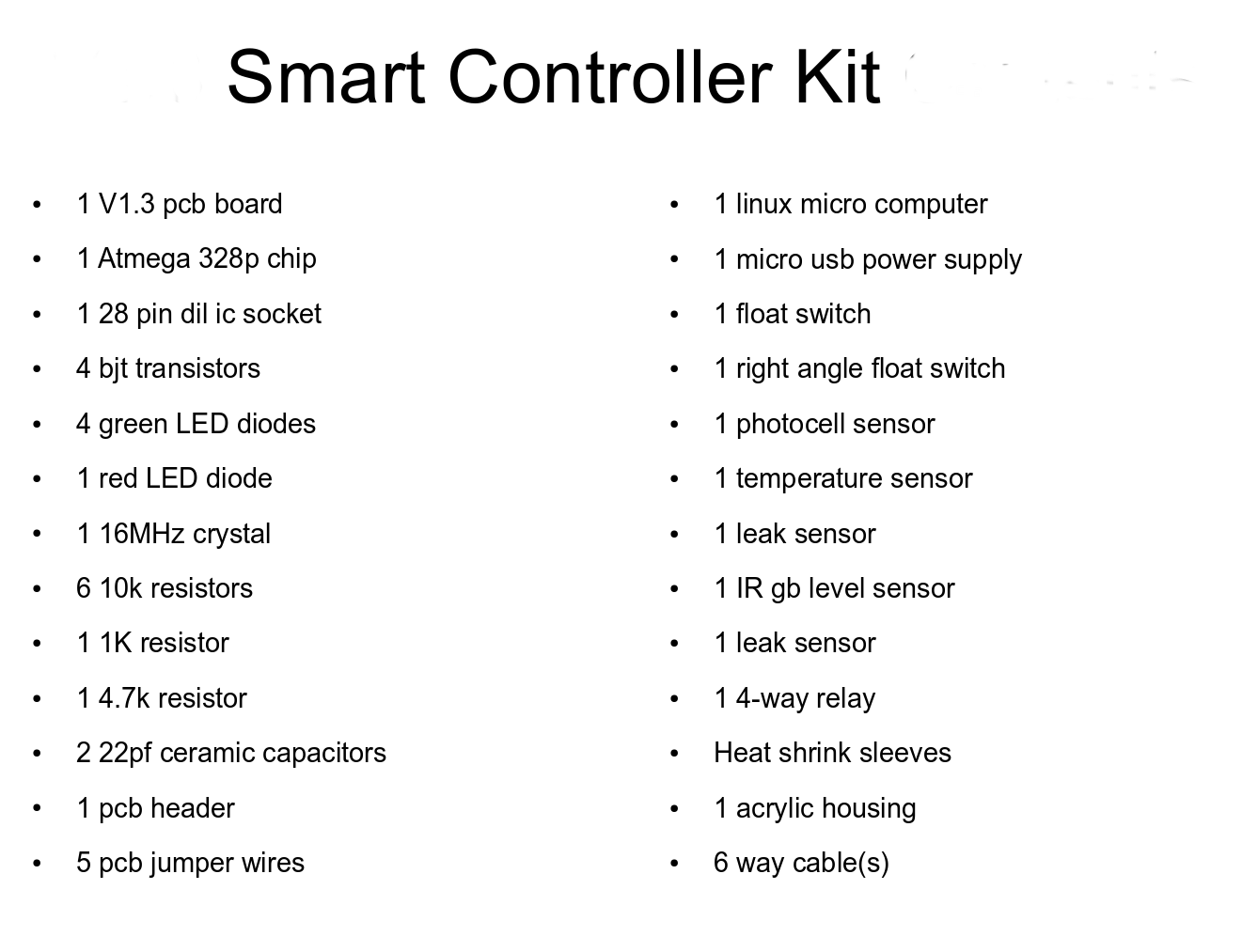
The following are the electronic components used to build the smart controller boards.
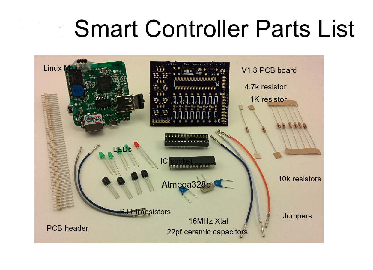 a larger list is shown below.
The Atmega Code
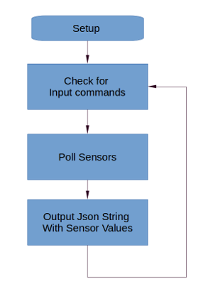
An overview flowchart for reading sensors and listening to commands is shown below:
typical program section snippets are shown below.
Proram Name: kijnaigrowsSmartControllerV1
Input: Sensors
Output: json serial string with sensor values on uart0
typical declaration of sensor and relay pinouts
void setup() {
pinMode(PUMP, OUTPUT); //fish tank pump
pinMode(RESERVIOR, OUTPUT); //reservior
pinMode(HALLSENSOR, INPUT); //initializes digital pin 2 as an input - interupt 0
pinMode(FLOWSWITCH1, INPUT); //flow sensor 1
//serial ports
Serial.begin(baudRate); //linux
}
typical looped section polls sensors and listens for relay instructions
void loop() { //arduino main loop
serialReader(); //check for input commands
/check sensors
isTankFull();
isIsFlowRate;
//calculate flowrate
}
typical sensor logic snippet
float whatIsFlowRate(){
waterIsFlowing = digitalRead(FLOWSWITCH1); //is water flowing
float flowRateLPerMin = measureFlowRate(); // measure flow rate in liters per min
float flowRateGalPerMin = flowRateLPerMin * 0.00440286754; //flow rate in gal per min
Serial.print("\t\"flow_rate_sensor\": { \"flowRate\":");
Serial.print(flowRateGalPerMin);
Serial.println("},");
}
typical program json output on the serial like is shown below:
{
"report": {
"initialize":{"initializing":0, "baudRate":38400, "version":"v1.3.1"},
"arduino":{"uptime":"00:00:03:40"},
"tank_level_sensor": { "full":0},
"flow_rate_sensor": { "flowRate":0.00},
"flow_switch_sensor": { "flow":0},
"reservior_level_sensor": { "full":1},
"leak_detector_sensor": { "leak":1,"measured":67.00},
"gb_level_sensor": { "gbLevel":106.82, "measured":6.52, "water_height":7.48, "max":14.00, "min":1.00},
"photocell_sensor": { "lightLevel":68.00},
"temperature_sensor:{{"sensorCount":2},{"count":0,"temperature":18.56},{"count":1,"temperature":19.44},"temperature":19.44,{"units":"Celcius"}},
"fish_tank_pump": { "on":0},
"reservior_pump": { "on":0},
"grow_lights": { "on":0},
"fish_feeder": { "on":0},
"endString":{"end":1}}
}
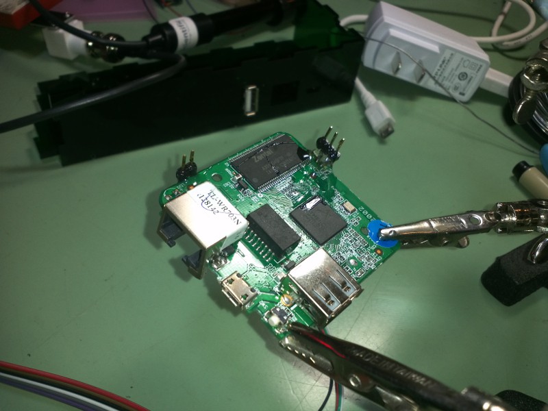
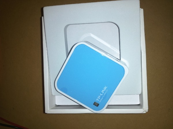
Hacking and Installing Linux on the Tp-Link wr703n
the tp-link wr703n is a wifi hotspot with usb that costs around $20. we will hack this to expose the pinouts we need, followed by a custom openwrt kernel install, install the smart control package files, configure this to work with the smart controller board via the serial lines and finally getting our application to connect and send data to the remote database for visualization and alerting.
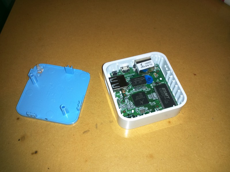
breaking the warranty
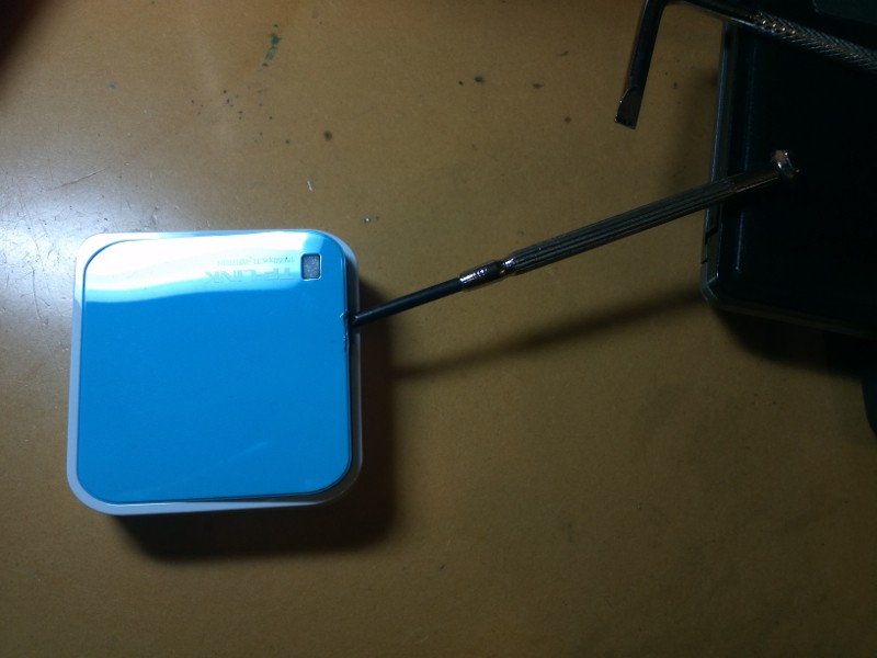 broken warranty
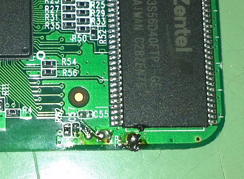
 tp_out and tp_in are the two solder pards marked on bottom of board. these are the serial pins tx and rx respectively for uart0. we will expose these for our application
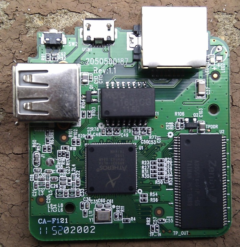 tin the serial connection points. a third point is anchored for grounding by scratching the pcb mask off as show below
 a right angle pcb header is then soldered to these points
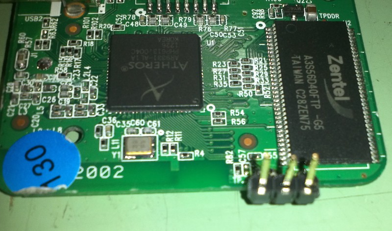
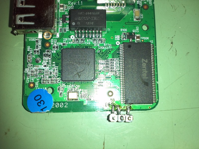 a different perspective for the uart0 connection is shown below:
exposing power connections, these will be used to power the sensor board. this is done on the underside of the pcb to add a right angle pcb header connection
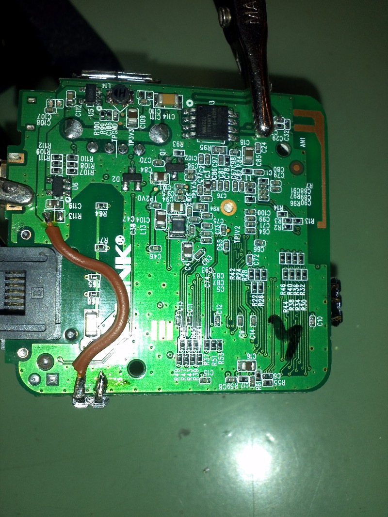 modified tp-link wr708n router, with power and serial pcb header connections