Close
0%
0%

Smart Aquaponics

Harnessing Nature, Linux And A Phone To Feed Ourselves

Similar projects worth following
Mimicking and modeling natural processes that sustain life on earth is critical for humanity to colonize new frontiers. The biggest challenge is that natures processes take like forever while humans live for a limited short time – so people take shortcuts leading to most sustainability issues facing the earth today.
Smart aquaponic systems can autonomously mimic the earths water cycle and model nitrogen cycles, oxygen cycles etc. to grow healthy organic produce for feeding new and existing colonies
This smart aquaponics project involves using modern fabrication technologies to build an aquaponic garden, establishing biological life balances in the garden, assemble the electronics kit and sensors, software programming and finally remote database configuration for monitoring and visualization.
We will hack a wr703n router into an Openwrt Linux microcomputer, build a standalone arduino compatible board and connect the two for a powerful IoT smart controller application

Energy can neither be created nor destroyed, it can only change form. The source of earth's energy is the Sun. 71% of planet earth is water, which stores the Sun's energy. Water changes it's state into gas when hot and into a solid when cold. Water in the oceans vaporizes and evaporates on sunny days. Wind blows the vapors inland and rises up when it reaches land. This causes condensation, and this moisture turns into clouds. Precipitation occurs and the moisture falls as rain. Water runoff causes rivers to flow back to the oceans with minerals. Infiltration makes underground rivers flow to the ocean as well. Plankton and other plants start growing in the ocean. As well as plants grow on land. And the oceans and land evolve and fill with life. Bacteria evolved cleaning the ocean & keeping the balance. This balanced model is what we mimic with smart aquaponics 
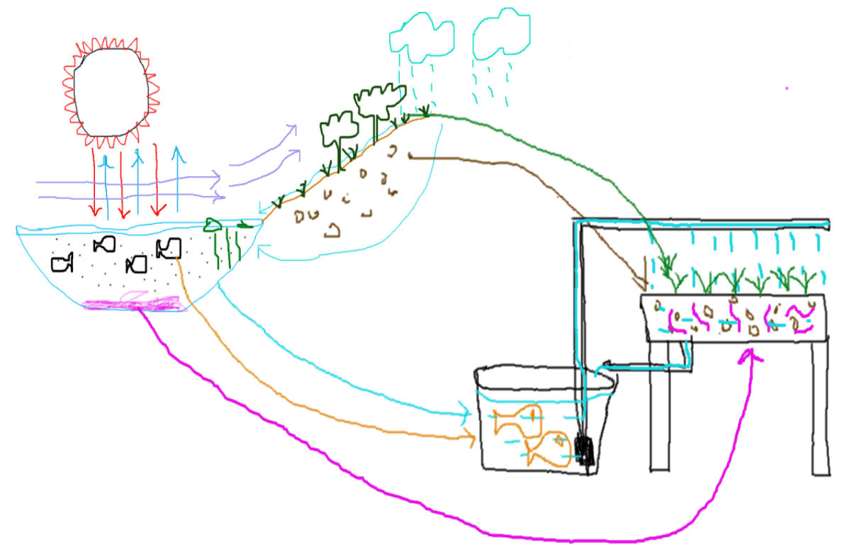
 We start the model using a fish tank. In the tank, water and fish mimic the ocean. A gravel filled bed mimics the land. Recirculating water between the tank and grow-bed recreates the watercycle. Flora grows on gravel in the grow-bed. Bacteria colonizes the gravel, composting & filtering waste. Balance & sustainability is attained … until ...…Humans come into the picture. Humans farmed the land to create food . Nutrient runoff from human farms break the ocean's ecosytem. Similarly, our models break as soon as we add human elements to it. Smart aquaponics turn physical gardens into data... Mitigating many issues.

A functional overview of a smart aquaponics systems is shown below:
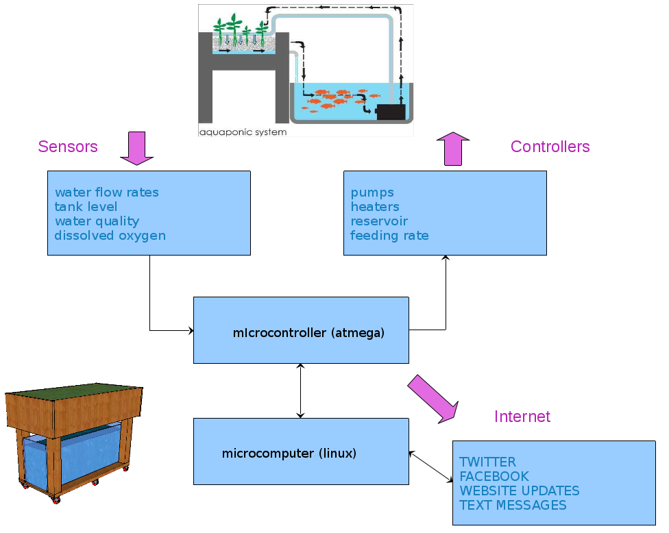
linux makes it very easy to control the arduino. rather than write scary firmware, we abstract the arduino code as much as possible so it only reads sensors and reports the values while accepting basic commands for flipping bits or voltages.. ie. sensor and relay driver logic only. all decisions are made using higher level code. eg. turn on lights and reports how bright they are. linux decides when or why or how to respond next. further, running openwrt on the $20 tp-link router replace like 50 shields. wifi, ntp, sdcards, webservers usb - video, audio, cellular links not to mention linux tools like crond, sshd, grep, awk, sed etc and fun ones like python, nodejs, javascript etc.  oh is it also so cheap as compared to raspberry pi, beaglebone, dun etc. based solutions.

the micro controller part in this project is a standalone arduino compatible board using the atmega328. the function of this is to read sensors and drive actuators.  it handles sensor logic and reports the status of the connected sensor through a json. string object in the serial line uart0. ie. turn on lights command is issued, light sensors reports lights are on.,

the linux computer sees the atmega part as a serial device, similar to a printer or keyboard connected to it. the linux micro uses the 'serial to  network' ser2net utility to convert the atmega serial device into a network socket. so the sensors and relays on the atmega board can easily be accessed in linux using regular tcp/ip tools or as a device file /dev/ath0.

the data is then sent to a remote database application for data logging, monitoring, visualization, alerting, sharing and remote control.

Smart Controller Functional Overview
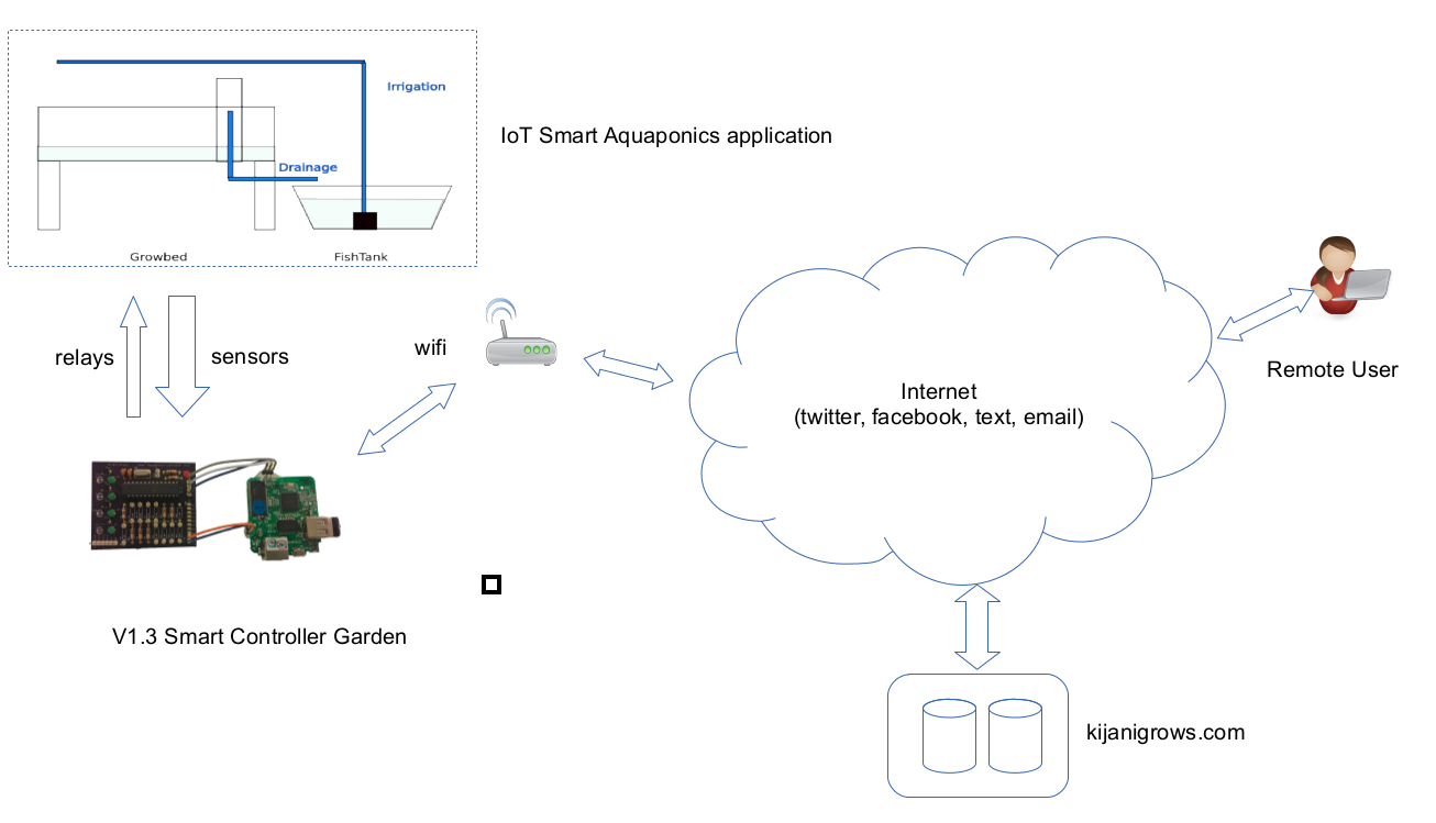
functional  parts of the smart controller overview and some data flow is shown above. the two pcb boards show above are the atmega based smart controller board and the linux microcomputer board.  the following stages will dig deeper into each individual block. 

The Atemga Microcontroller Functional Block
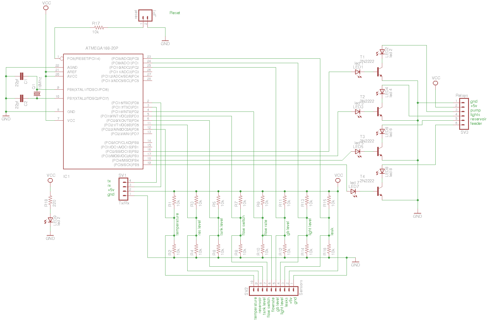
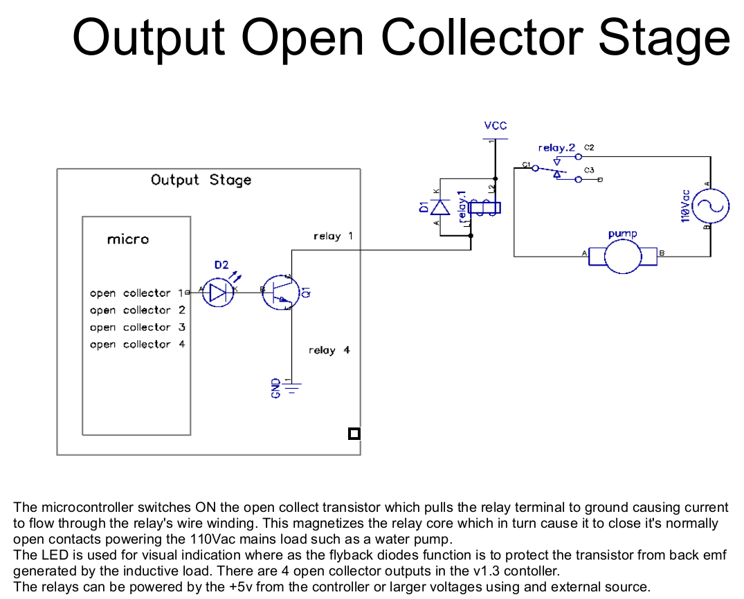
there are three main functional blocks, the atmega328 standalone brains, the input section consisting of pullup/pulldown resistors chains and an open collector output stage. there is also a uart section for connecting with the linux microcomputer and a power indicator section.

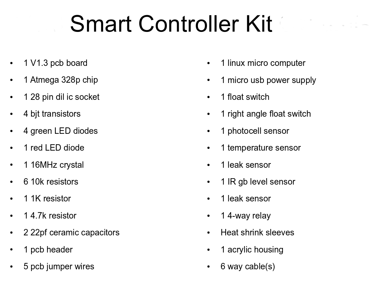
The following are the electronic components used to build the smart controller boards.
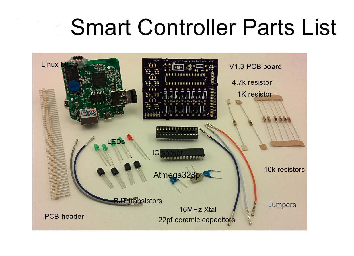
a larger list is shown below.

The Atmega...

Read more »

  • 1 × v1.3 smart controller pcb board
  • 1 × tplink wr703n router
  • 1 × atmega 328p chip
  • 1 × 28 pin dil ic socket
  • 4 × bjt transistors

View all 17 components

  • kj2arduino - it's all starting to coming together

    kijani grows07/01/2015 at 12:24 0 comments

    and its so fun and easy to use

    i designed the v2 smart controller boards such that i could connect any inputs(sensors) or outputs(actuators, relays) on any pin without having to update the firmware on the board or external interface components..

    the only thing you need to use a v2 smart controller board is a unique hostname and wifi(or ethernet) connection. you can connect any digital, analogue, 1-wire, 12c, serial sensors to the pins and the board will send the raw values of all sensors connected to the backend server . the api for retrieving your raw data is http://api.kijanigrows.com/v2/device/get/kj_v2_01 (where kj_v2_01 is my office garden). in response is the raw pin data sent from the controller (i don't know if it is temp, a float switch, leak, noise etc they are just raw readings)

    "pins": {
    "D38": 0,
    "D30": 0,
    "D31": 0,
    "A15": 417,
    "A14": 456,

    user, device and sensor profiles are defined and mapped in the backend. say A4 is assigned to a photocell sensor, and D30 to a float switch, raw values are converted to the to correct values here. say A14:456 could be mean that an ir sensor connected on pin A14 measured 4 feet. or that D30 :0 means that a leak sensor connected on pin D30 has detected no leak yet

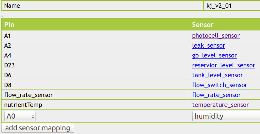
    the library kj2arduino makes it possible to assign pins dynamic characteristics that you would normally need firmware on the board to do. the sensor mapping interface is show below:

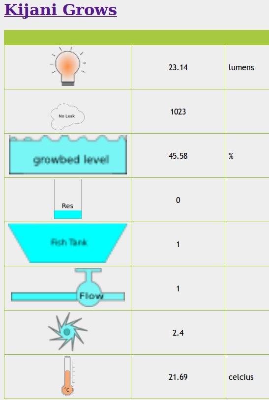
    typical ui with mapped sensor elements decoded using kj2arduino

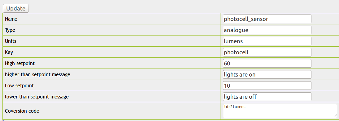
    the colors change based on sensor present values. you can change sensor set points, units, conversion code and messages using the sensor screen below::
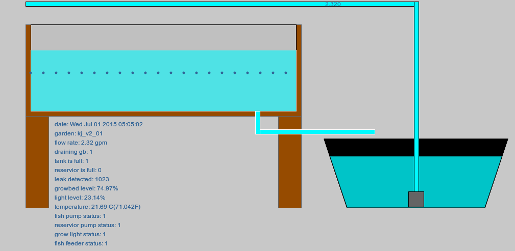
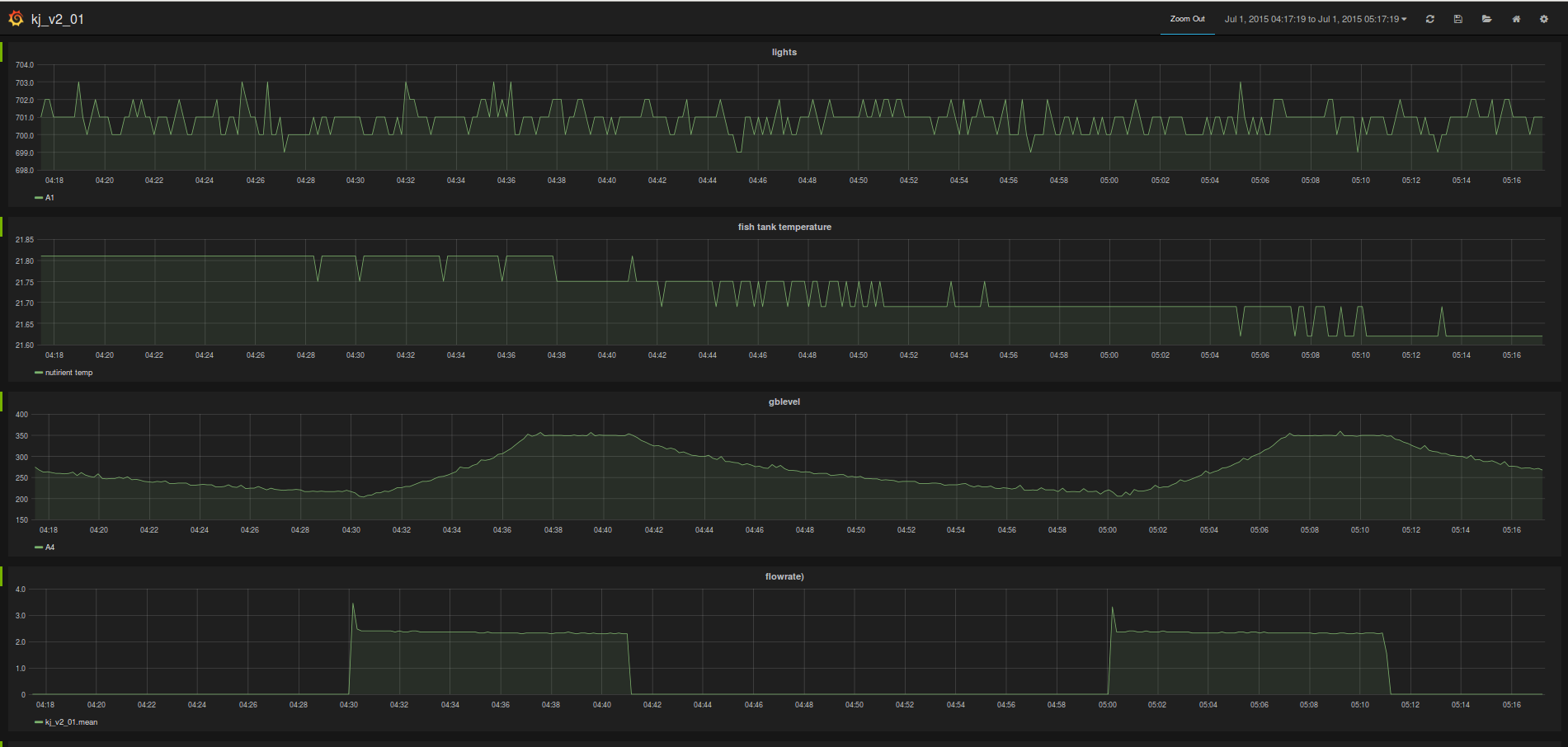
    more visualizations of my kj_v2_01 office garden done with v2 and kj2arduino

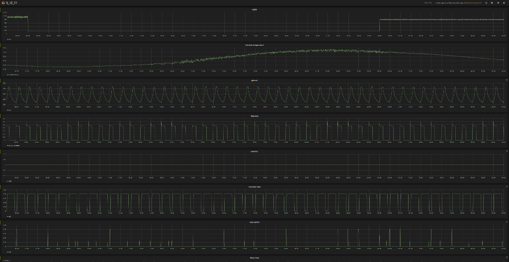
    grafana graphs of the same data ... this are raw values straight from an influxdb server

    and lots of other goodies with the v2 board, video streaming//timelapsing, remote control ui, alerting etc

    so ... in short you need to use a v2 for your next project ... comes with all the software

  • v2 smart controler based garden visualizations

    kijani grows04/23/2015 at 22:27 0 comments

    we finally figured out most of the critical bugs on the v2 controller boards, things are never as easy as it seems - i guess building your own custom linux computers from scratch was not going to be as easy as i thought it would be. this one really tiny smt resistor that was picked and placed in the wrong orientation took almost 2 months to catch since i thought it was a kernel or software issue, but we are good to go now. here are some v2 visualizations of my office garden ... ... does your flood and drain garden behave the same as mine http://db.kijanigrows.com:8080/grafana/#/dashboard/db/kj_v2_01

    the visualizations are done using influxdb and grafana as per this tutorial in in my website

    here is a live video url from this garden

  • v2 testing and debugging is coming along

    kijani grows11/04/2014 at 12:58 0 comments

    always takes longer than originally anticipated.. fixed hardware bugs and waiting on new updated boards from the east.

    working on software platform ... this is fun - a different kind from electronics ...

    see updated video 3 for more information

  • debugging v2 bootloader issues

    kijani grows08/21/2014 at 04:56 0 comments

    debug software can be frustrating. debugging hardware can drive you crazy. debugging hardware combined with software is not for those faint at heart. debugging, software, hardware combined with a real life problem that takes at least 60 mins before you can see the results of your debugging efforts is fun to say the least.

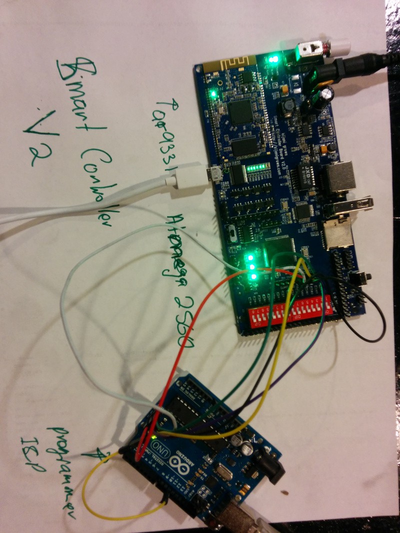
    spend all day trying to figure bootloader issues on the atmega 2560. my day seems to be filled with  fuses and lock bytes. the bootloader and program seem to be stepping on one another. i am using an arduino as an in circuit programmer.

  • kijarduino - an interpretation of arduino, pi and beaglebone

    kijani grows08/20/2014 at 09:13 0 comments

    what would you make if you had a chance to build your own computer from scratch... we came up with the kijarduino  ... an atheros linux atmega 2560 combination. we finally got our first prototypes back from shenzhen. this is the next step in the evolution of our boards. we will talk more about this and others over the next couple of weeks ... back to my debugger for now.

  • evolution of the linux based smart controllers

    kijani grows08/14/2014 at 10:06 0 comments

    pivoting is fun. changing directions while still sticking to your dreams.

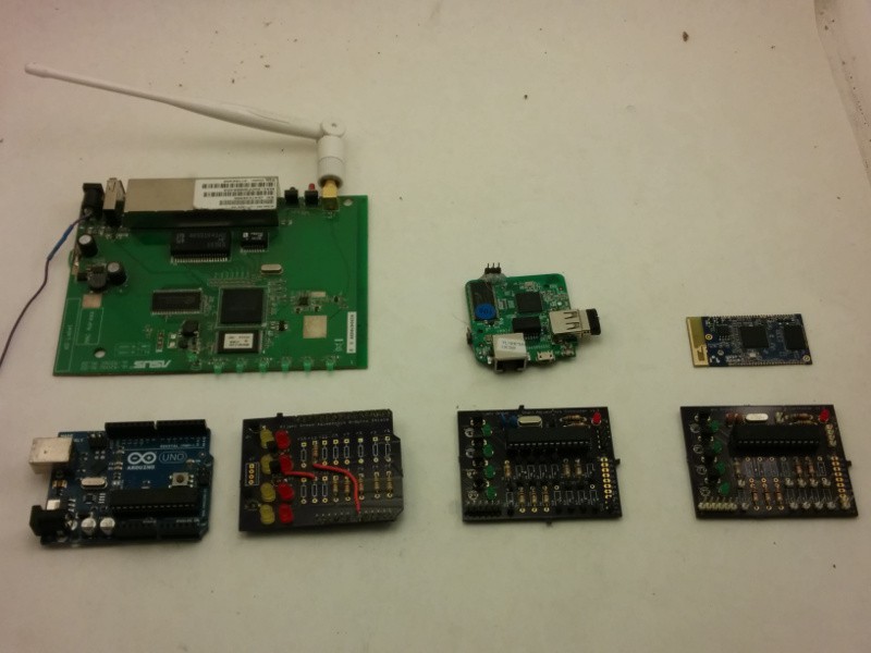
    r&d, prototyping  can be an expensive process . below are shown the different devices we have used for linux controllers and also how the shields evolved into stand alone boards. the steps indicate design for prototyping, designing for cost, and designing for production. finally but not shown are the series designed for marketing.

    on the left is the origiinal assu wg520 router that we initially hacked as an openwrt router, with arduino and shield.  the middle set shows the wr703n based linux microcontroller with a stand alone atemega controller board. and the one on the right show the oolite gainstrong ar9331 wifi module that we now use for hacking into a linux microcomputer for our projections. guess the price ... under $10 ... for a powerful linux computer.
  • hacking the wr708n for production

    kijani grows08/13/2014 at 08:10 0 comments

    whereas using the wr708n router as a linux microcomputer  to front for atmega is fun and  cheaper than the current linux microcontoller solutions, it involves hacking the board by modifying surface mounted components. a process that is ok for hobbies but can soon become a  headache  for production. it is also possible to use the  beaglebone, or pi for the same function but this is a more costly solution. the transition from hobby to business has been one of the biggest challenges as prototyping and testing is an expensive endeavor. so how to make cost efficient and more reliable products is one of the daily quests ... it seems looking east is where many answers lay.

View all 7 project logs

  • 1
    Step 1

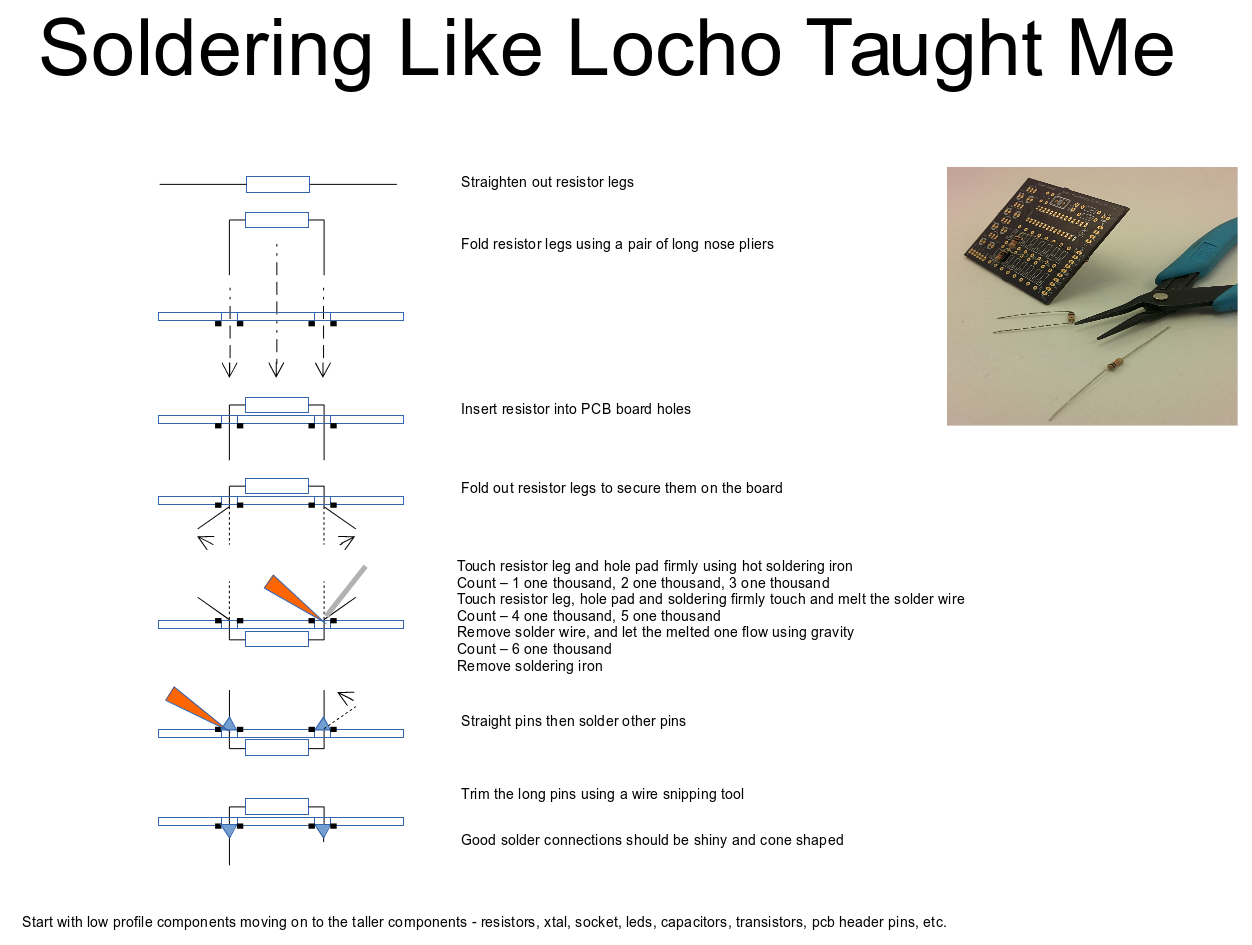
    Soldering is an acquired skill

  • 2
    Step 2

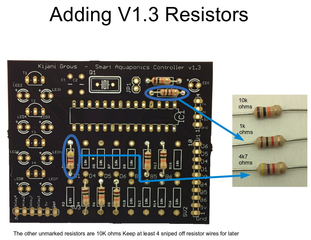
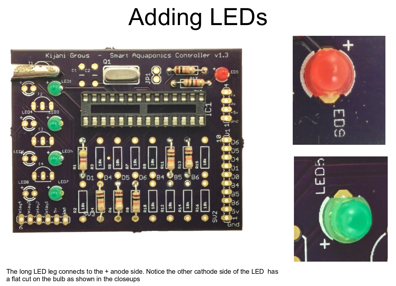
    We start with the components that have the lowest physical profile going up.

  • 3
    Step 3

View all 4 instructions

Enjoy this project?

Share

Discussions

kijani grows wrote 12/09/2014 at 03:44 point
i started adding more information at the knowledge base section on our site. http://kijanigrows.com

  Are you sure? yes | no

Ben Ahrens wrote 08/21/2014 at 04:30 point
Your LED current limiting resistor size calculation Vcc/If neglects the fact that the voltage across the resistor will not be the full 5V. Your power calculation, on the other hand, assumes Vcc - Vf volts across the resistor. Why the difference?

  Are you sure? yes | no

kijani grows wrote 08/22/2014 at 00:10 point
just me being a goof ball. the doc's are for explaining design considerations. given the voltage and current ratings most preferred components with values close by will most likely work. but yes, i should consider all potential drops in my calculations.

  Are you sure? yes | no

sbrulais wrote 08/17/2014 at 07:40 point
Hi,
Power dissipated by the resistor: (5-2.1)*0.02= 0.058W assuming 20mA is going through the LED (which is not true now). When you don't know the current P=V²/R=2.9²/220=0.038W
So 1/4W resistor are ok ;-)

  Are you sure? yes | no

Gareth Coleman wrote 08/08/2014 at 12:30 point
Hey - great project! I've tried the Atlas pH probe and I was disappointed, to be honest. Their support forum seems of limited value and their stuff is expensive. Also the probe was completely destroyed after only a couple of months continuous use. We had much better results with a cheap probe (£7 vs £50 for the Atlas one) and a circuit from Sparky's Widgets - it's open source and Ryan is responsive if you have questions or issues. Good luck!

  Are you sure? yes | no

zakqwy wrote 07/15/2014 at 12:30 point
How do you plan to measure DO? In my experience, getting that value accurately can get a bit spendy, and the sensors often need regular maintenance.

  Are you sure? yes | no

kijani grows wrote 07/16/2014 at 08:37 point
nature does not dependent on absolute values ... rather how the different variables relate to one another ... which is one of the objectives for this project, to model after nature. dissolved oxygen in water depends on many things including, temperature, time of day, water quality, biological mass etc. there are many ways to monitor and respond to oxygenation issues without instrumentation. that said, i like the devices from http://atlas-scientific.com ... their probes are relatively professional, stable and they have replacement membranes for their dissolved oxygen probes.

  Are you sure? yes | no

zakqwy wrote 07/16/2014 at 09:58 point
Great call--if you're looking for relative values, a galvanic device will probably work well. That probe from Atlas isn't too expensive either, which is nice. Good luck!

  Are you sure? yes | no

Similar Projects

Does this project spark your interest?

Become a member to follow this project and never miss any updates