Please see the project logs for extensive documentation! The code and all schematic/design files are available on GitHub (see link on the left side). Please also watch the demo video!
0%
0%
Become a Hackaday.io member
Already have an account? Log in.
Just one more thing
To make the experience fit your profile, pick a username and tell us what interests you.
Pick an awesome username
hackaday.io/
Your profile's URL: hackaday.io/username. Max 25 alphanumeric characters.
Pick a few interests
Projects that share your interests
People that share your interests

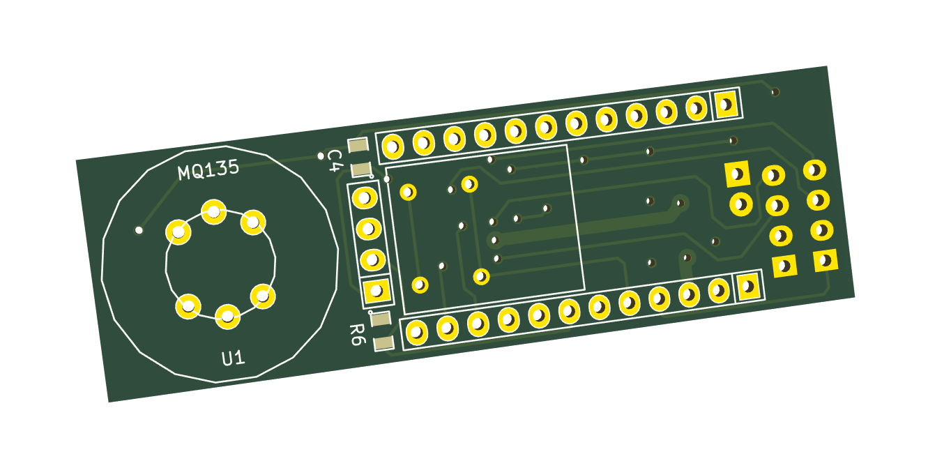
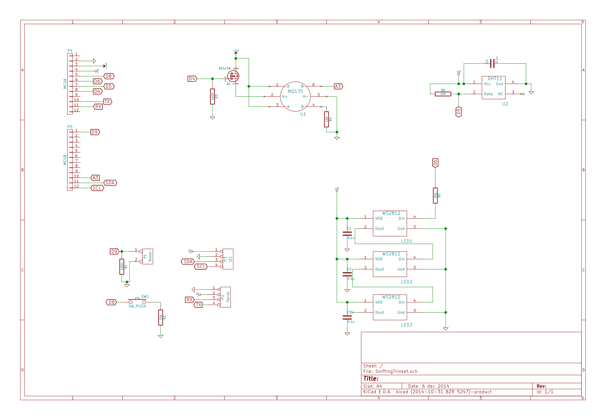
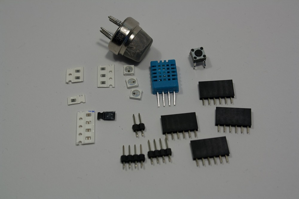
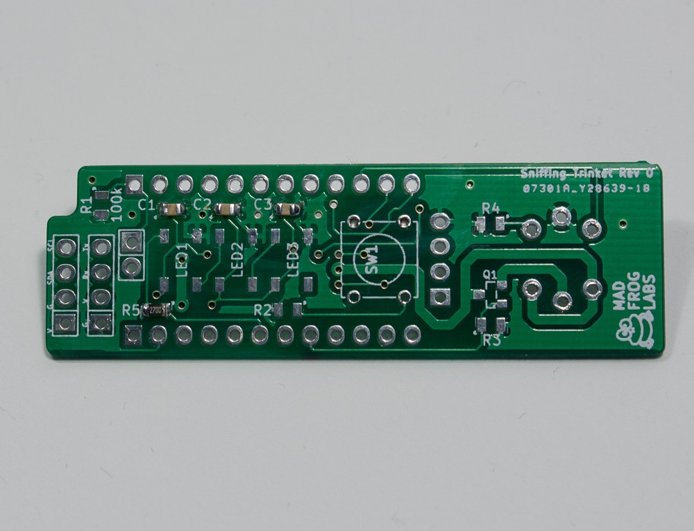
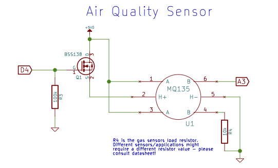 For the current version I use a MQ135 sensor. This sensor is sensible to various gases (Benzene, Alkohol, NH3, CO2) and marketed as an air quality sensor but in a normal environment it is in principle only sensing CO2 (more on that in a later post). The sensor has an internal heating element connected to the H+ and H- pins. The heating of the sensor draws about 130mA of current, which is quite a lot and the sensor has to be continuously heated during operation. This might not be necessary or desirable in some applications, therefore Q1 acts as a switch for the heating of the gas sensor. Q1 can be controlled by the trinkets D4 pin and a pulldown resistor (R3) ensures proper operation. Q1 is a standard logic level FET, other types should work as well if they can handle at least 200mA switching current and have a low on resistance. The gas sensor changes its internal resistance between the pins A and B depending on the amount of eg. CO2 in the air. Together with R4 it constitutes a simple resistor divider, that is read out via the trinkets A3 input. There are other gas sensors with the same pinout and footprint for various gases, Depending on your application you may switch to a different sensor, they should all work but you may have to adjust R4 accordingly.
 The DHT11 sensor has a digital output, so the schematic is simple: Hook it up to power and ground and the data pin to the trinkets D5 GPIO and you are fine. R6 is a necessary pull up resistor for the data pin and C4 a bypass cap for the power supply.
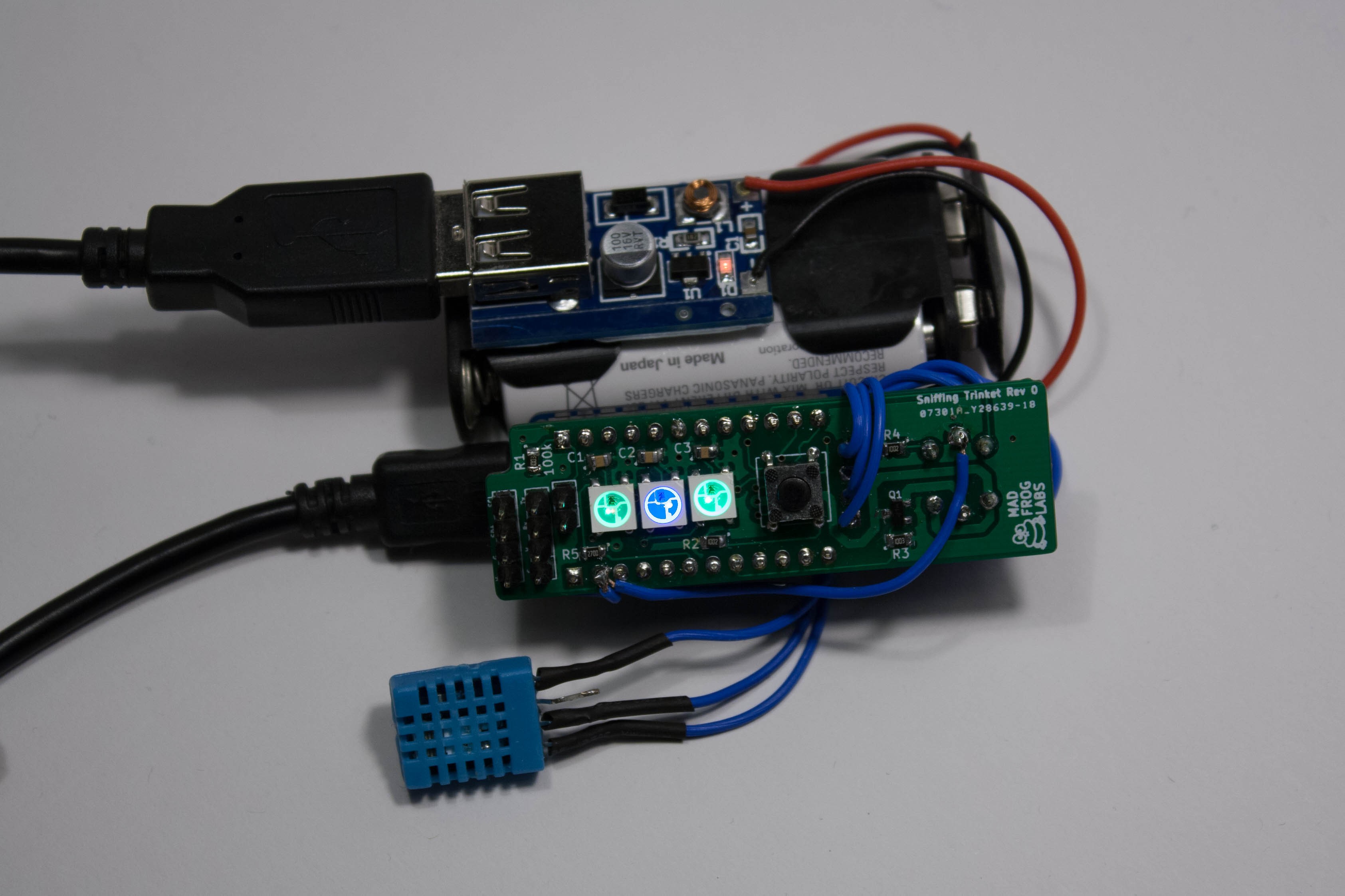
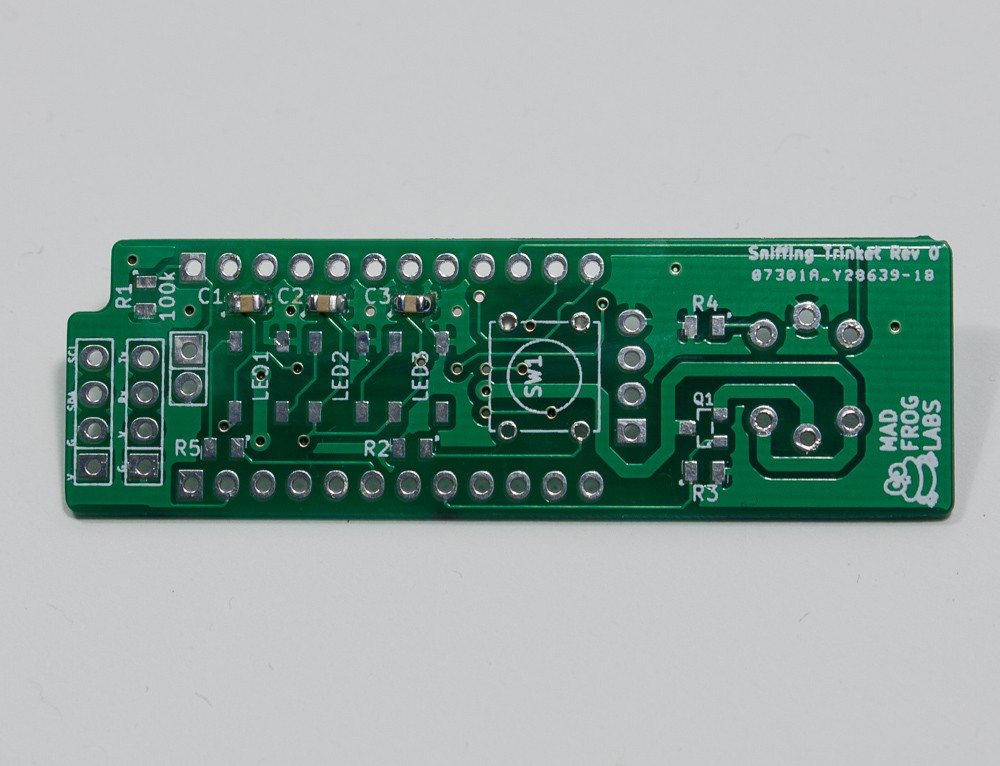
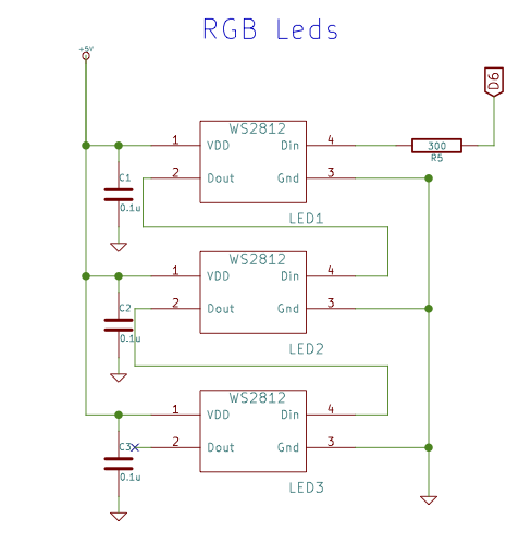 The main output of the project are three WS2812b RGB Leds, one each for Temperature, Humidity and CO2. The user can give lower and upper limits for these measurements, the leds are green if they are within range or blue/red if below/above the limit. The color output is continuous (ie. there is a smooth transition from blue->green->red depending on the actual measurement). The WS2812b variant has four pins, supply voltage and Gnd, Data in and Data out. The data is fed to the Leds by the D6 GPIO of the trinket, R5 is for protection and proper operation an C1-C3 are bypass caps.
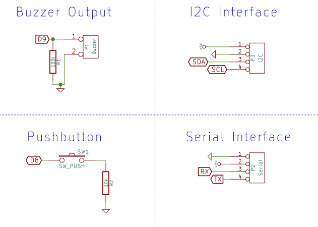 Four additional IO options are available. The pushbutton will be used to switch between different modes of the software. The buzzer output can be used for a piezo or to switch something depending on an alarm that can be preset in software (eg. open a window if air is bad). The serial interface/I2C interface can be used to connect to a PC, display, ESP8266 wifi module or whatever you have in mind.
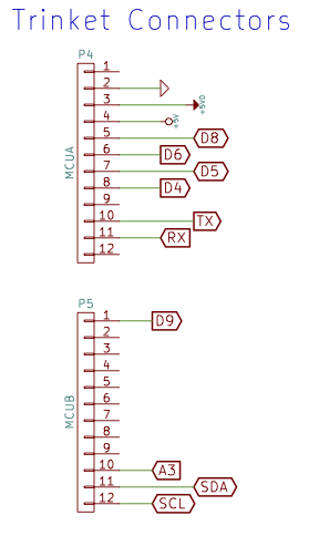 This represents the headers going to/coming from the trinket. Just collects all the signals. The MQ135 heater draws to much current for the trinkets LDO regulator, hence it is connected directly to the BUS pin of the trinket (ie. the USB connector).


 tiefpunkt
 Jason Webb
 Alex Hunt
I think you should use a Bosch bme280 for more accuracy,great project by the way