-
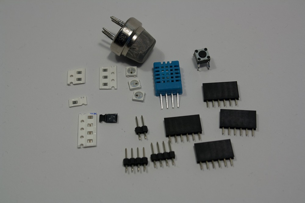
1Step 1
Get together all your parts (see BOM). You also need a PCB: Download the Gerbers and get them produced yourself (at least for the moment). Note that the PCBs have as of now (Christmas 2014) a couple of (fixable) bugs. Alternatively, you can build the project on a breadboard or perfboard - use through-hole-components then. If you use a PCB, make sure to read an SMD soldering tutorial and use the right tools.
![]()
-
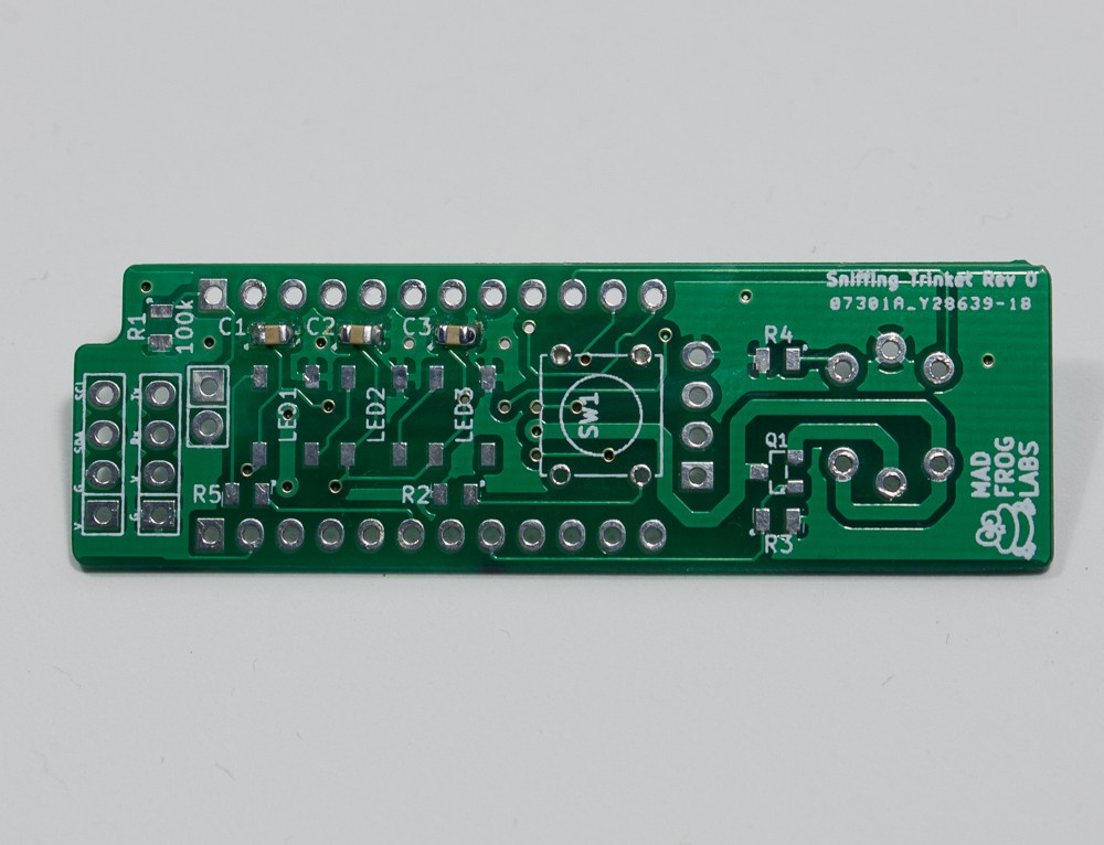
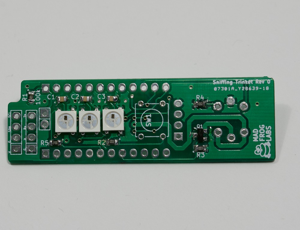
2Step 2
Start by soldering the three 100nF caps on the topside of the board (C1,C2,C3).
![]()
-
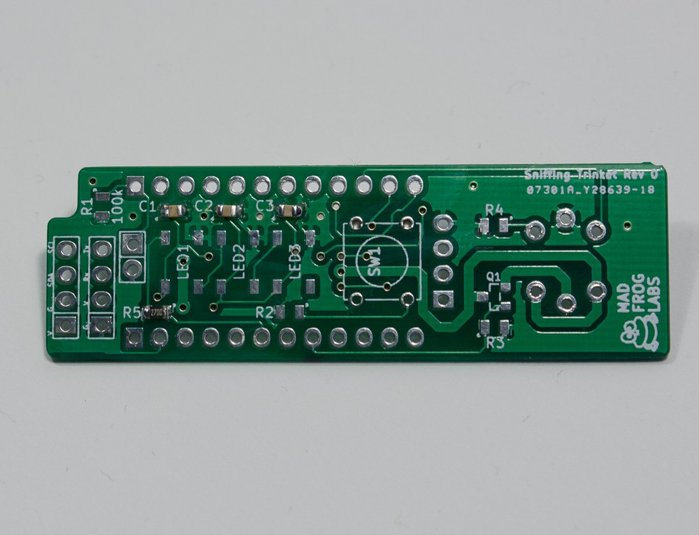
3Step 3
Solder R5, this is a 270 Ohm resistor (you may also use another value between 150 Ohm and 300 Ohm).
![]()
-
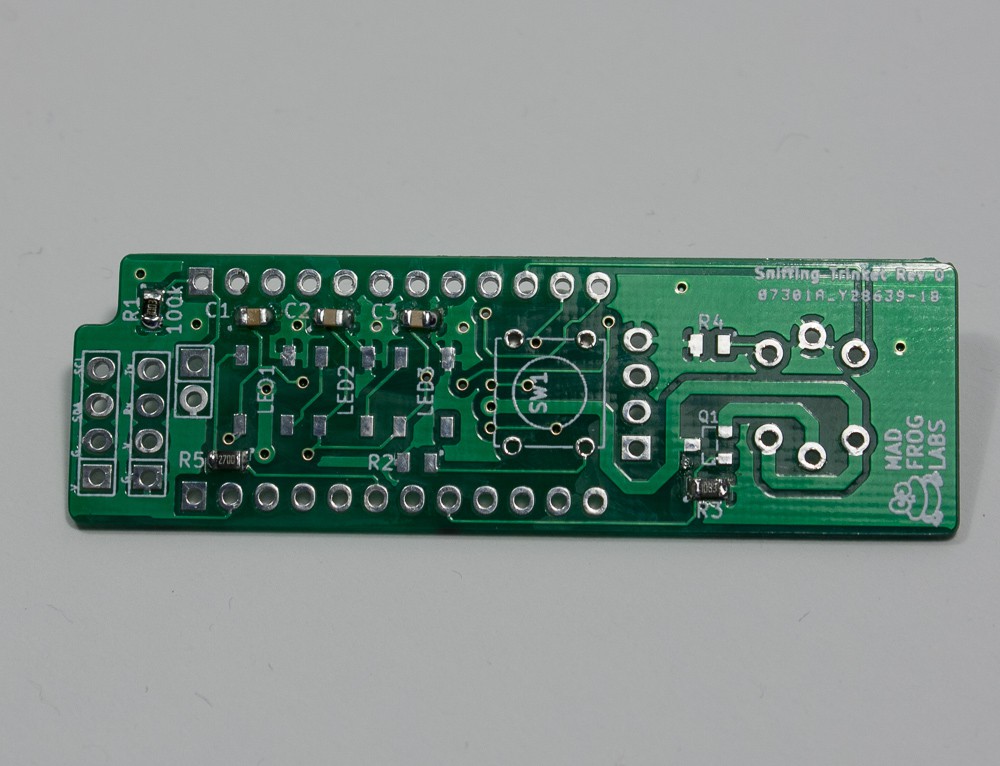
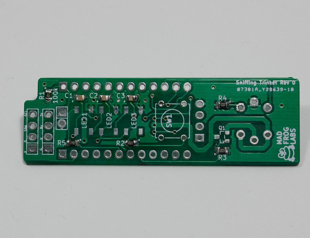
4Step 4
Solder R1 and R5, those are 100 kOhm resistors.
![]()
-
5Step 5
Solder R2 and R4, those are 10 kOhm resistors.
![]()
-
6Step 6
Solder the transistor Q1. Note: If you have a logic level FET with a lower on resistance than the BSS138, use that!
![]()
-
7Step 7
Solder the WS2812b LEDs. Note: They have a little cutout that must be oriented to the side of the capacitors. If in doubt, check the datasheet!
![]()
-
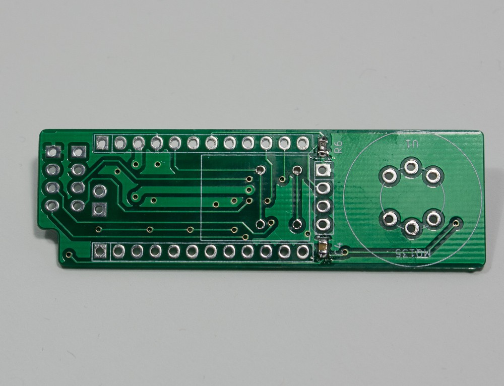
8Step 8
Turn the board over. Solder C4 (100nF) and R6 (10 kOhm).
![]()
-
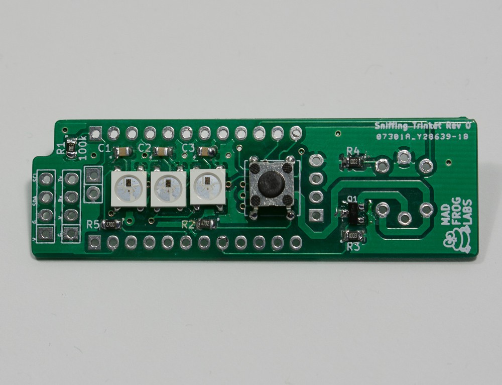
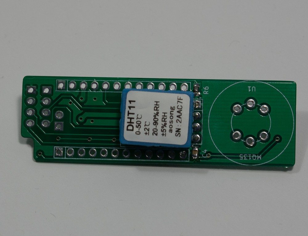
9Step 9
On the top side of the board, place the switch and solder.
![]()
-
10Step 10
Solder the DHT11 sensor on the bottom side as shown. Mind the direction of the pins! Note: I found that this placement is not ideal, as the heating from the gas sensor influences the temperature/humidity sensor. Instead is soldered the DHT11 on some wires and the wires to the board until I come around to redesign the PCB!
![]()

Discussions
Become a Hackaday.io Member
Create an account to leave a comment. Already have an account? Log In.