-
1Print STLS.
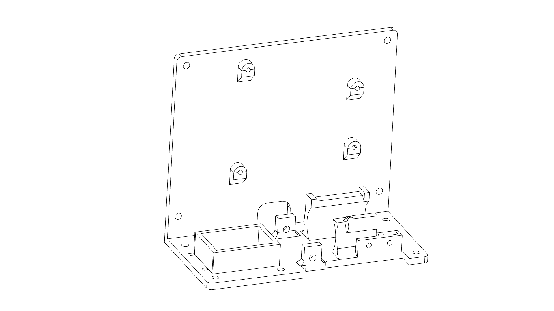
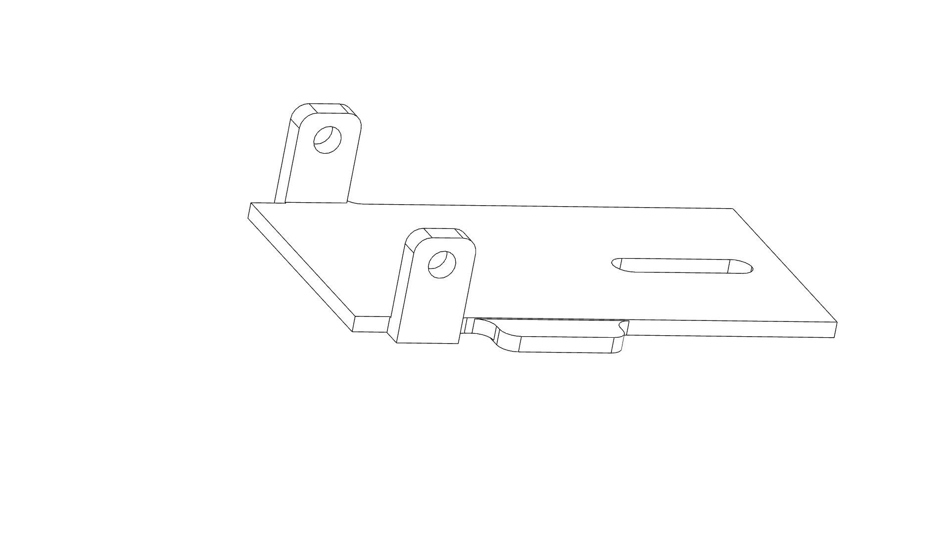
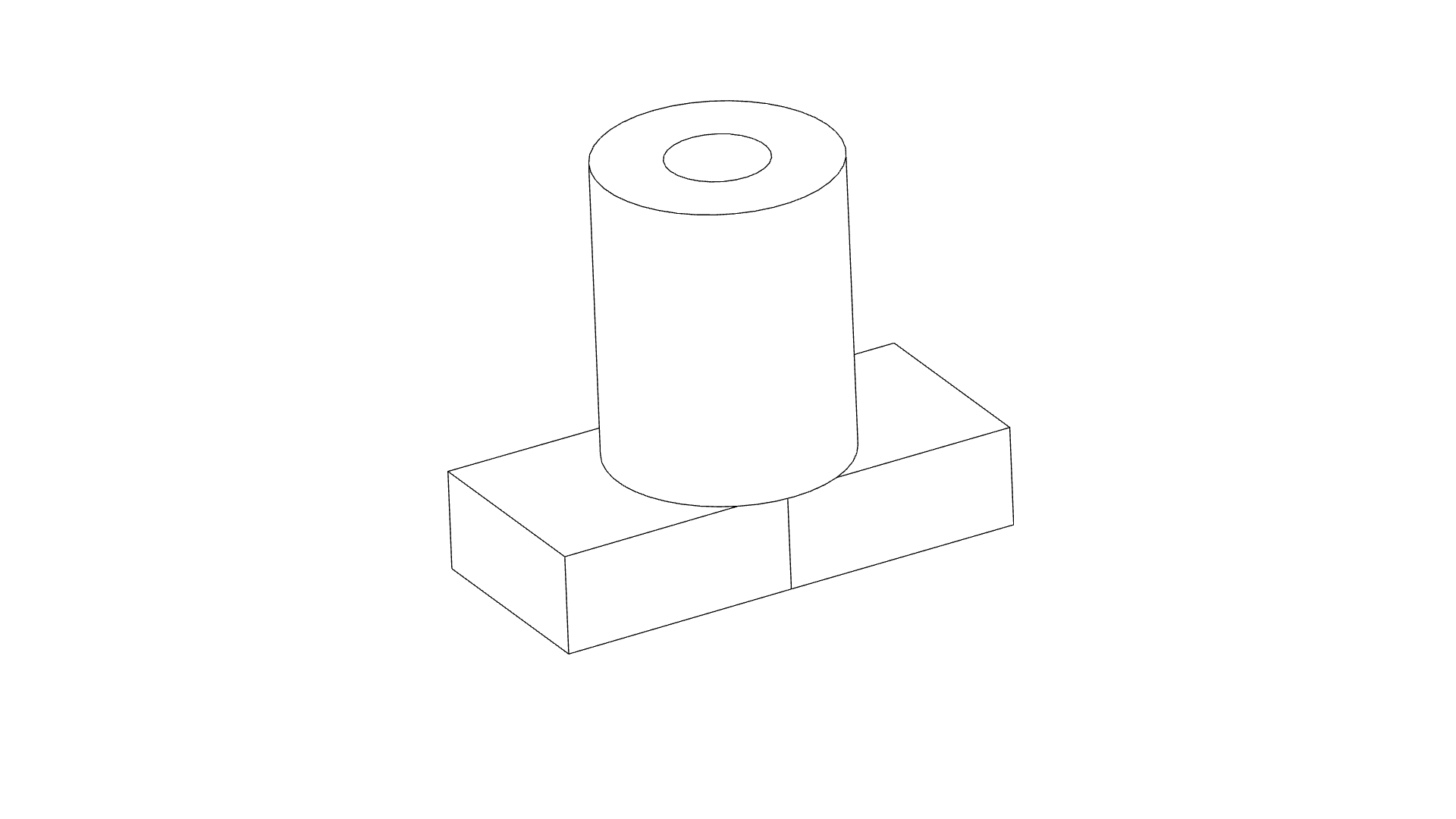
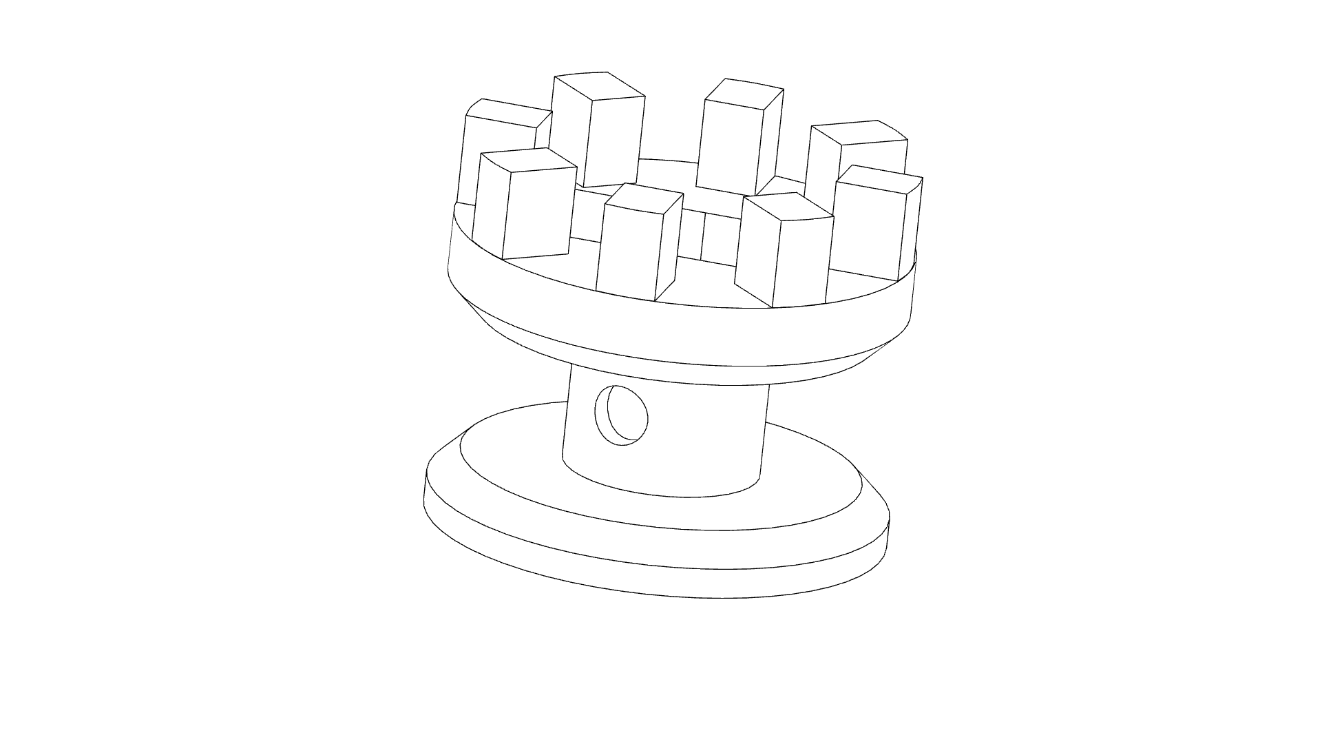
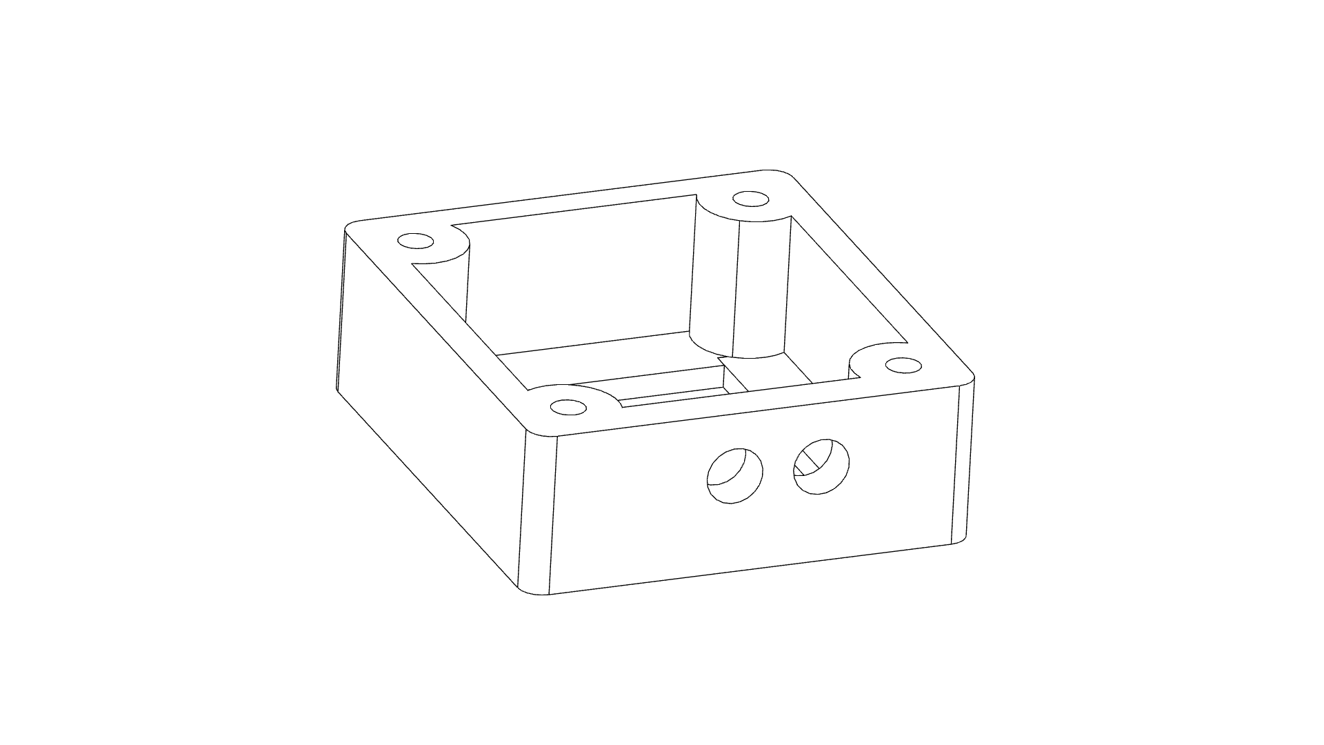
Print the STLS included in this build. There should be no support required for the main chassis, the spool will require support. Use tree supports if your slicer has this option The only change I recommend is having 100% infill around screw holes to prevent splitting of the PLA. The spider should be printed with 20% infill and upside down on an FDM printer.
Main chassis
![]()
Limit switch paddle
![]()
Drive boss
![]()
Spool/Pully
![]()
PIR sensor holder
![]()
-
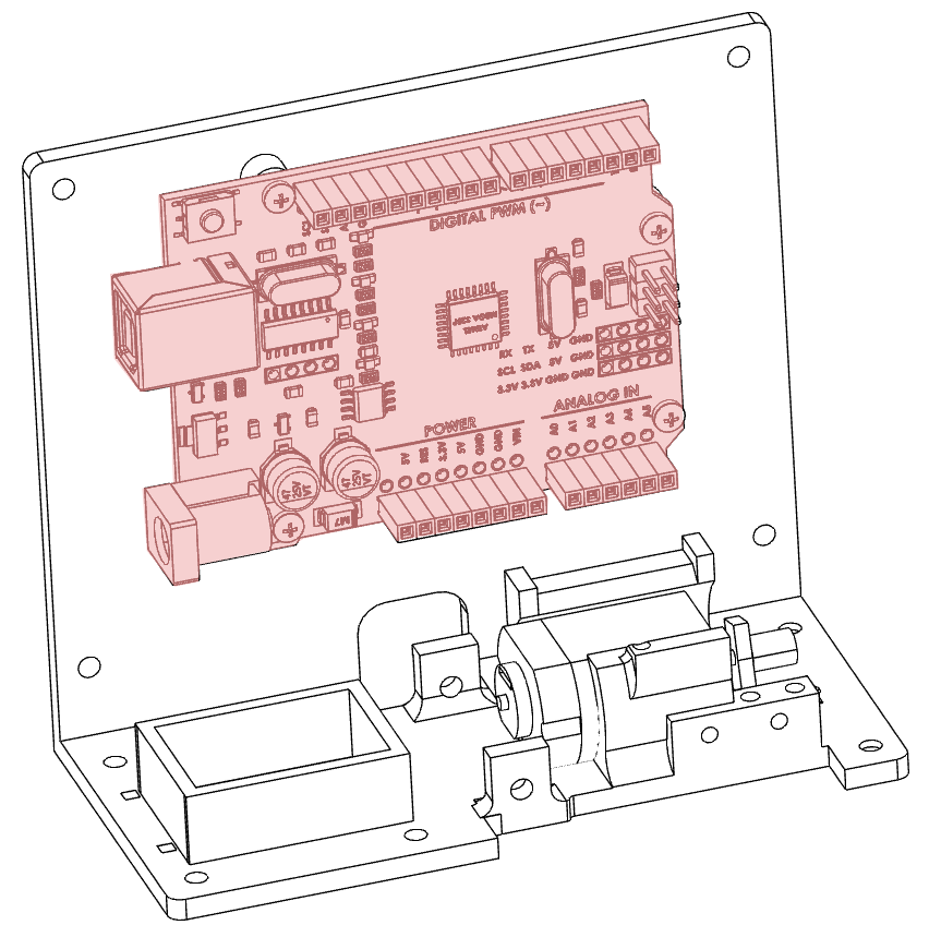
2Install Arduino
Screw the Arduino UNO into place using 4 6x3 screws. More details in the video here
![]()
-
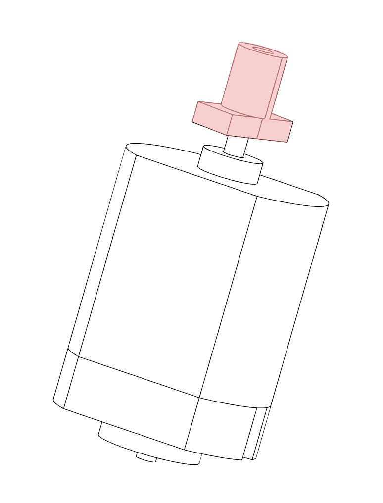
3Motor installation
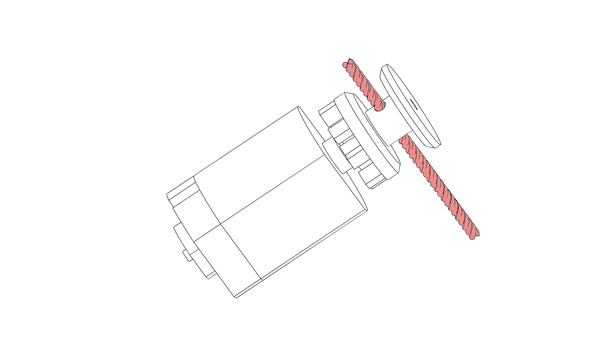
Using a small hammer tap the drive boss onto the shaft of the motor. More details on the video here
![]()
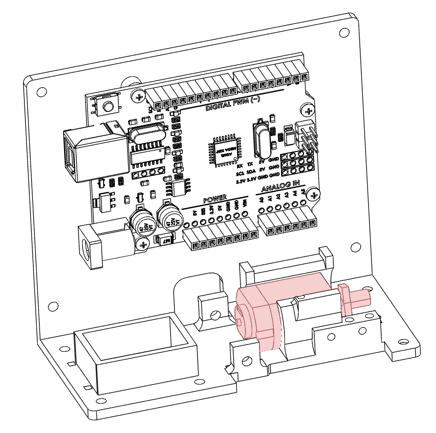
Slide the motor into the base of the chassis.
![]()
-
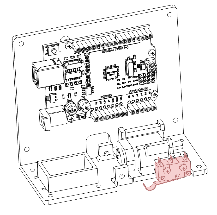
4Install Microswitch
The microswitch is installed into the front of the chassis with the two 2x16mm screws. One screw is fully tightened while the other is tightened just enough to hold the motor in place. More details are in the video here.
![]()
-
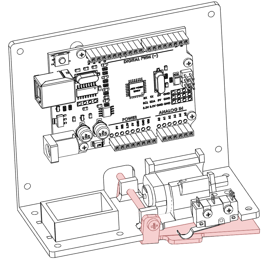
5Install limit paddle
The limit paddle stops the spider from driving too far up. The paddle is held in place by one 3x50 screw which runs across the chassis. The paddle should be able to move freely and without obstruction. When the paddle moves it should activate the microswitch. You should hear an audible click when the paddle is moved upwards.
![]()
-
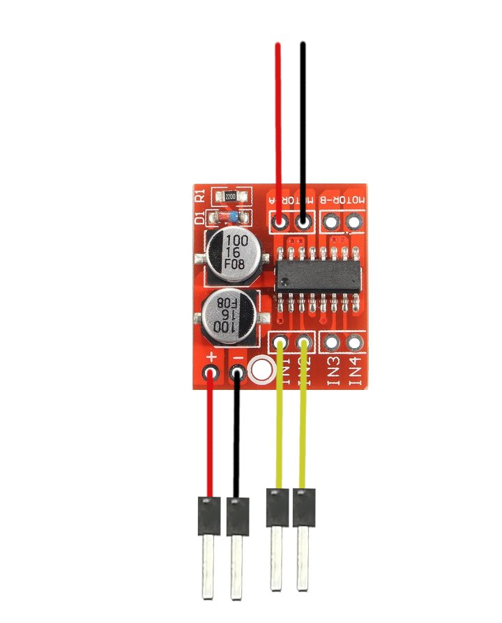
6Wire motor controller.
Prepare the motor driver for installation. The motor driver can drive two motors but we only need to use one for this project. Add a length of wire to each of the MOTOR A outputs. These will eventually be connected to our motor. Add a length of wire to the + and - terminals of the board. Then a length of wire to IN1 and IN2. Put a header pin on all but the motor wires to make installation easier later on.
-
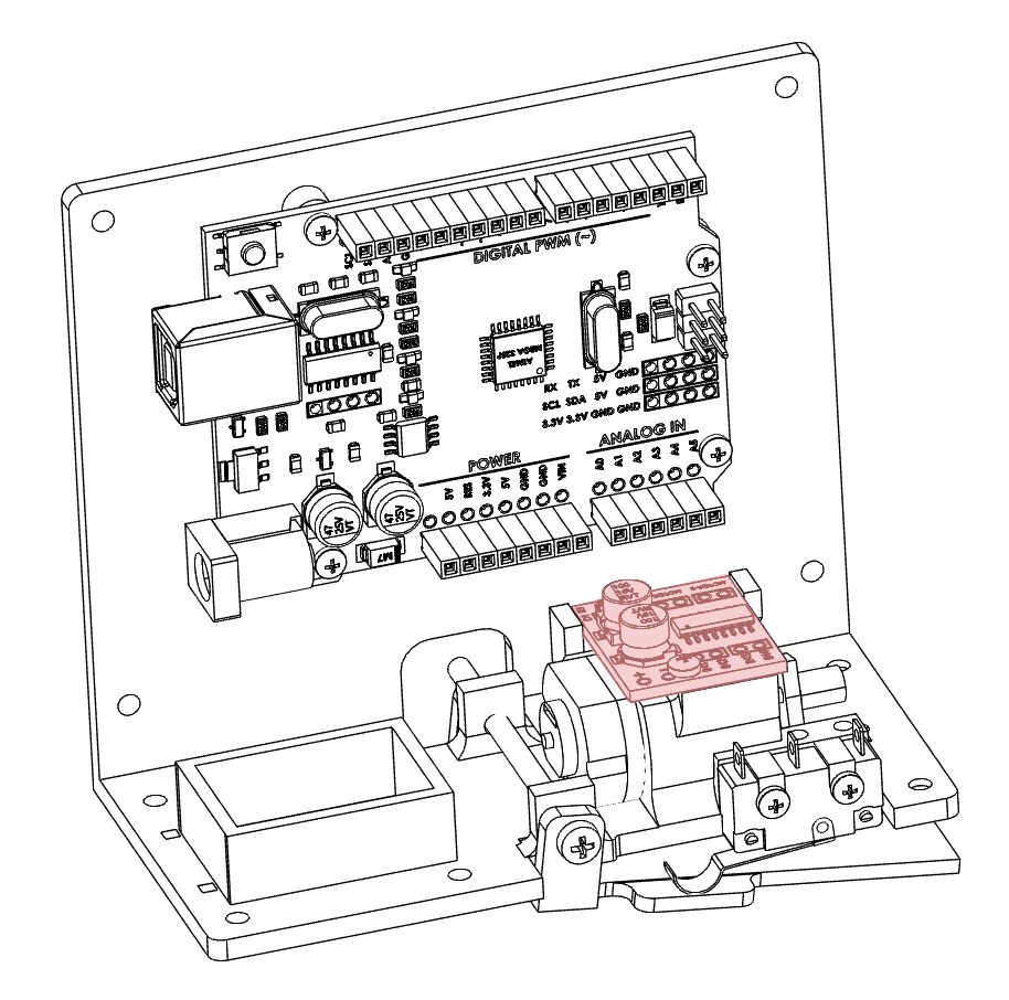
7Install the motor driver board
The motor driver board sits on top of the motor. There is a location for one screw and the rear of the board sits between two uprights. More details can be found here in the video.
![]()
-
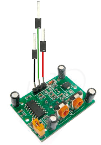
8Wire the PIR sensor
The PIR sensor has 3 connections Ground, 5V, and the signal wire. Attach a length of wire to each contact as shown below.
![]()
-
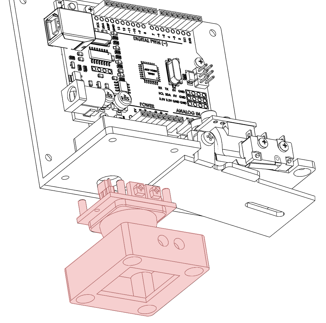
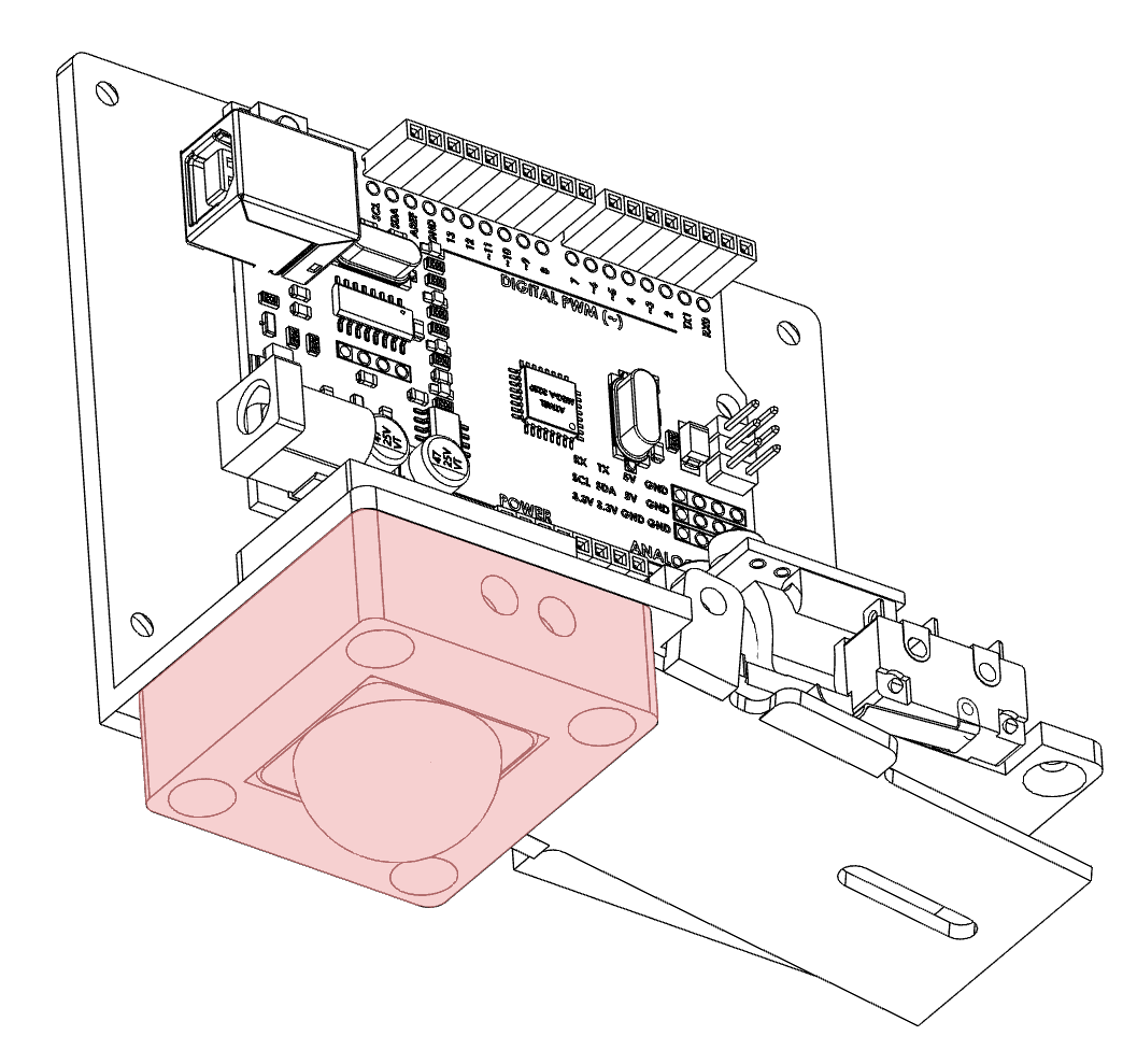
9Install the PIR sensor
Thread the wires from the PIR sensor through the hole in the base of the chassis next to the battery holder. Place the sensor in the sensor holder with the adjustment screws facing the holes in the sensor holder. Screw the sensor and holder into place. More details are in the video here.
![]()
Screw the cover into the chassis.
![]()
-
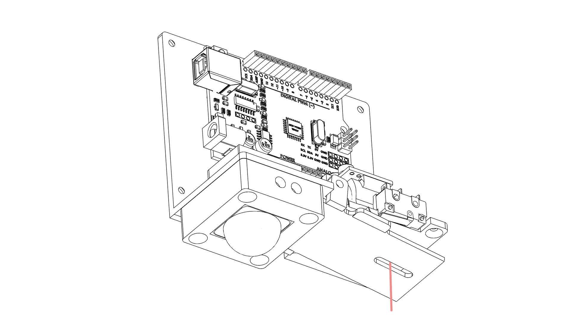
10Thread the spool
Thread your spider web (cotton) through the hole in the chassis and paddle below where the spool will go.
![]()
Then thread the cotton through the hole in the spool. You should be able to slide the spool over the drive boss which will keep the cotton in place.
![]()
Attach your spider to the other end of the thread.
Sensing spider prank (3D print Edition)
In this project, you will learn multiple aspects of Arduino while building an automated sensing spider.
 jasonwinfieldnz
Discussions
Become a Hackaday.io Member
Create an account to leave a comment. Already have an account? Log In.