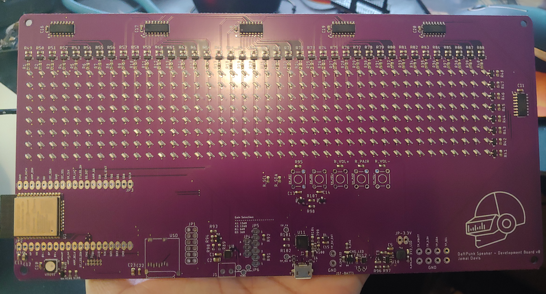
Designed development board to vet out project design while allowing for easy access to key test points (Power rails, I2C, I2S, and UART) and to test different hardware gain settings for the audio amp. This development board includes:
- ESP32 Module
- The LED matrix and shift register driving circuitry
- RGB status LED
- micro SD card
- I2S audio amp
- FTDI chip
- Fuel Gauge module
- 3.3V Buck regulator
- Push buttons (Volume, Pairing, Reset)
The development board was fabbed and assembled by JLCPCB, shown below:

 Jamal-Ra-Davis
Discussions
Become a Hackaday.io Member
Create an account to leave a comment. Already have an account? Log In.