-
1Cut out wood chassis
There are two options to get the chassis cut out. You can either print the PDF called template.pdf and glue this onto a piece of 4.75mm MDF or you can use the forcutting.pdf and get the wood laser cut. The laser-cut file is designed in such a way that it should only take a few minutes to cut your wood. Either method will yield the same result. For more details see the video here
-
2Glue chassis together
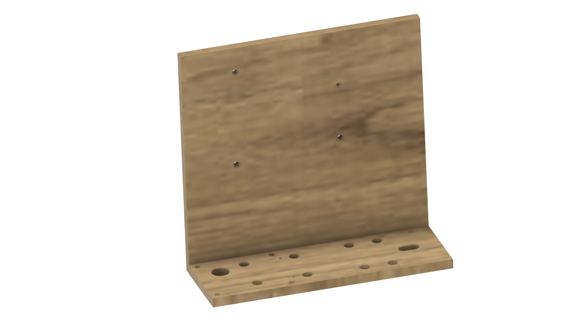
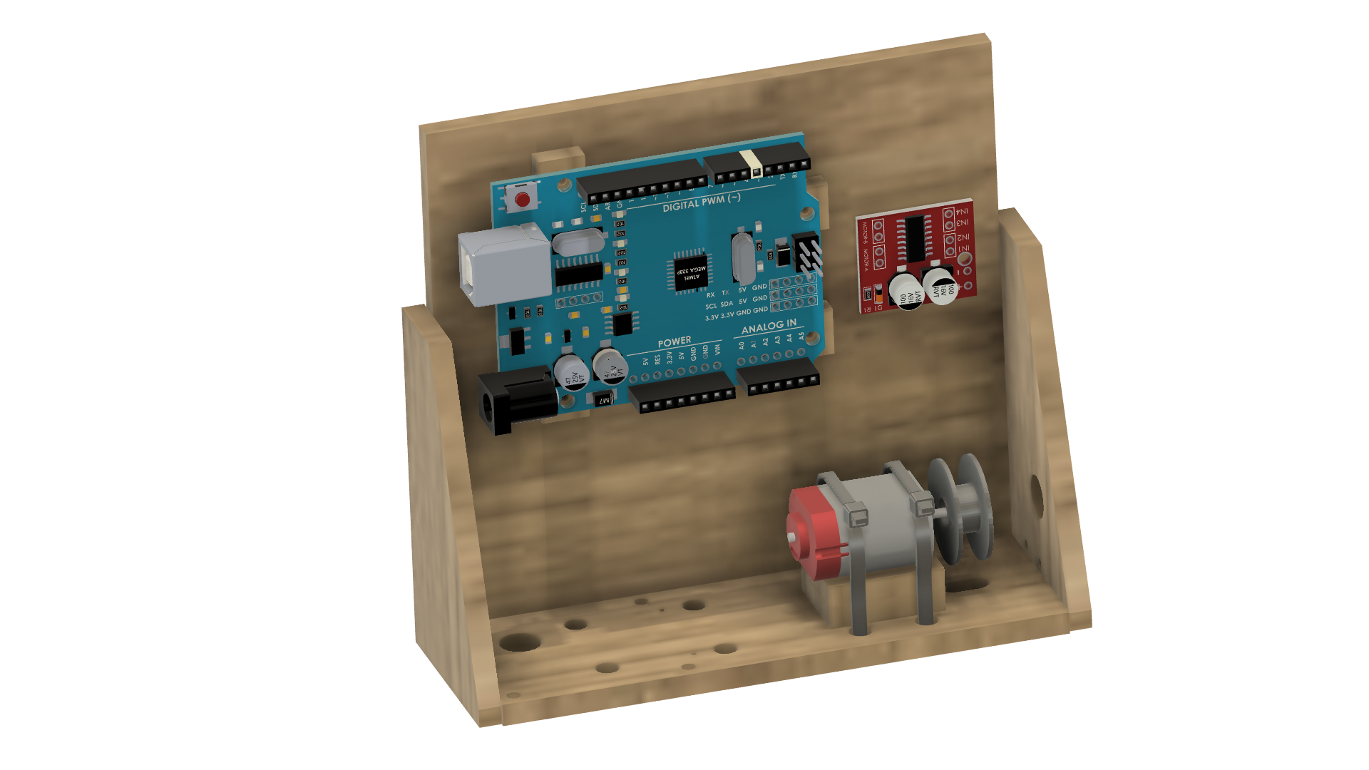
Glue the base of the chassis together starting with the back and the base. You should only need a good PVA glue. Note that the holes further apart vertically on the back go to the left. For the base, the slotted hole goes to the right and the large hole on the left goes toward the back. For more details see the video here.
![]()
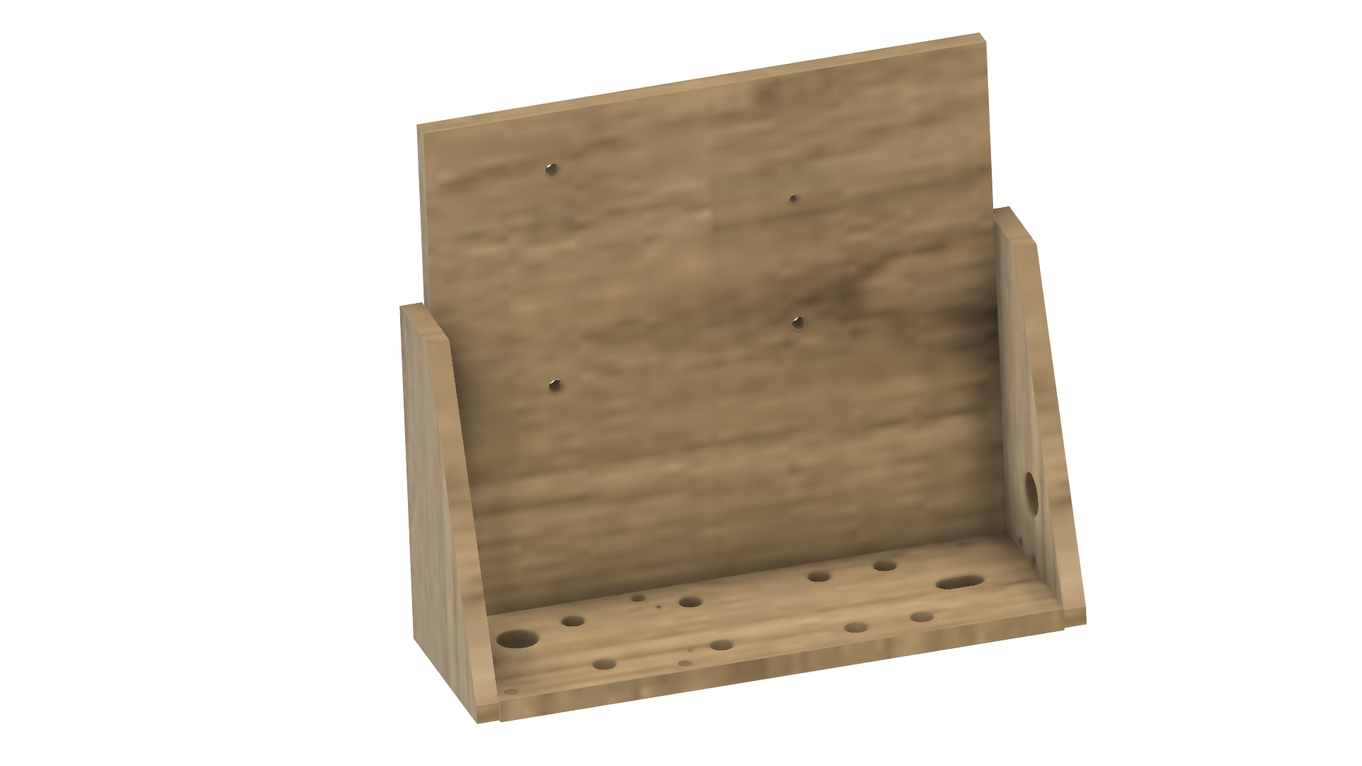
Add the left and right-hand side profiles. Note the profile with the holes goes on the right.
![]()
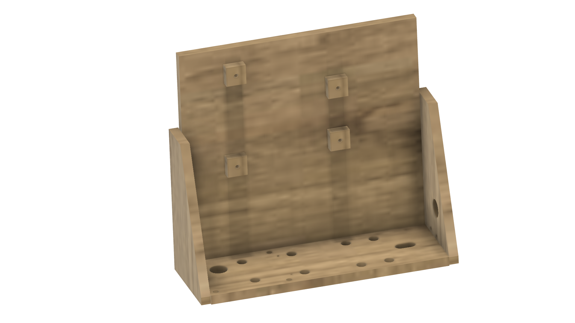
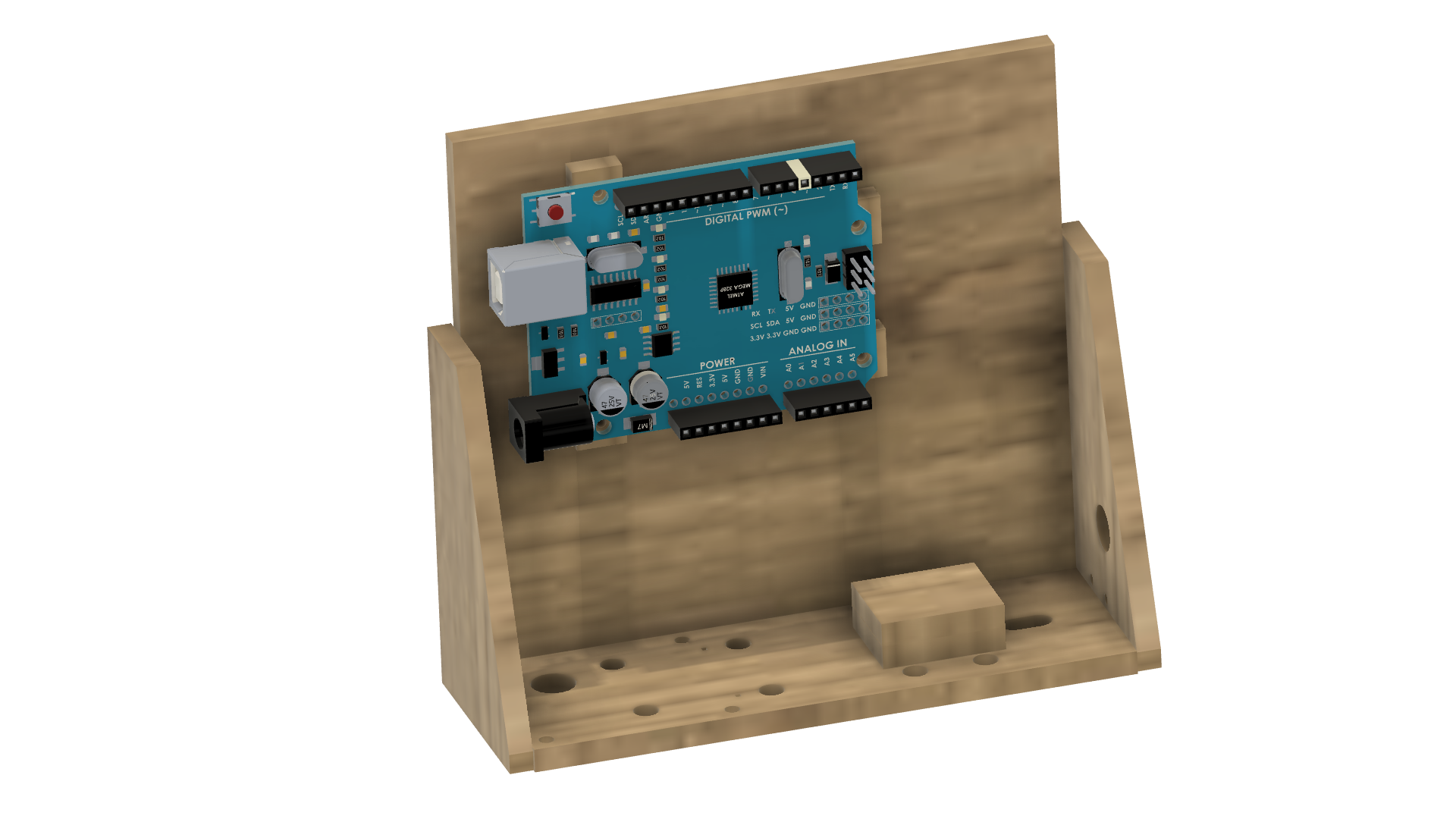
Glue the mounts for the Arduino on the back. I used nails to line up the holes but you could probably just do this by sight.
![]()
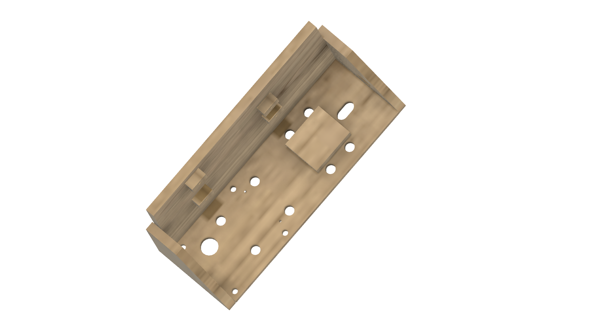
Glue the two motor mount cut-outs together then glue these to the base of the chassis between the two cable tie holes.
![]()
-
3Mount the Arduino UNO
The Arduino UNO screws into the mount holes in the back of the chassis. The mounts might interfere with the components on the bottom of the Arduino. If this is an issue you can sand off some edges of the mounts to suit.
![]()
-
4Prepare spool
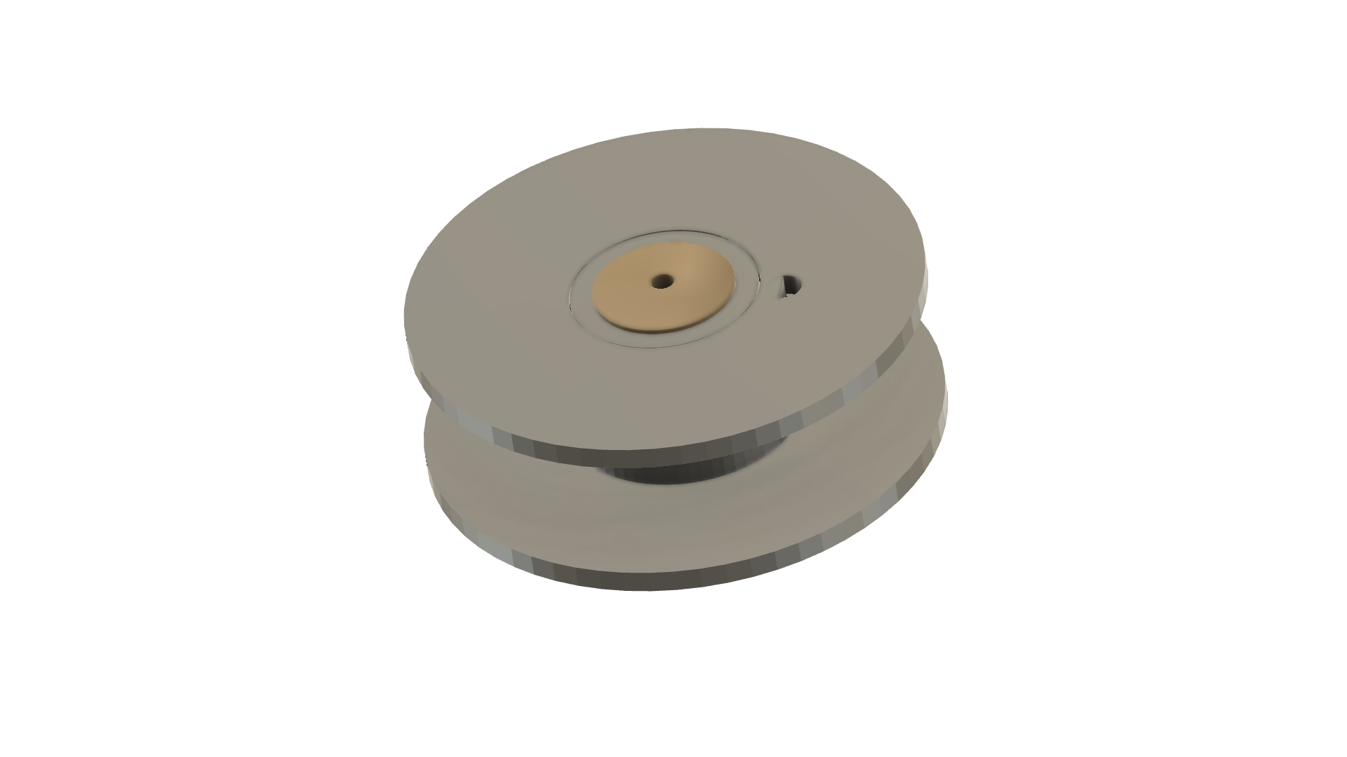
Hammer a length of dowel into the cotton spool and cut off the excess. Drill a small hole in end then carefully tap the spool onto your motor. This would be a good time to tie on one end of your cotton thread. For more details see the video here.
![]()
-
5Install motor
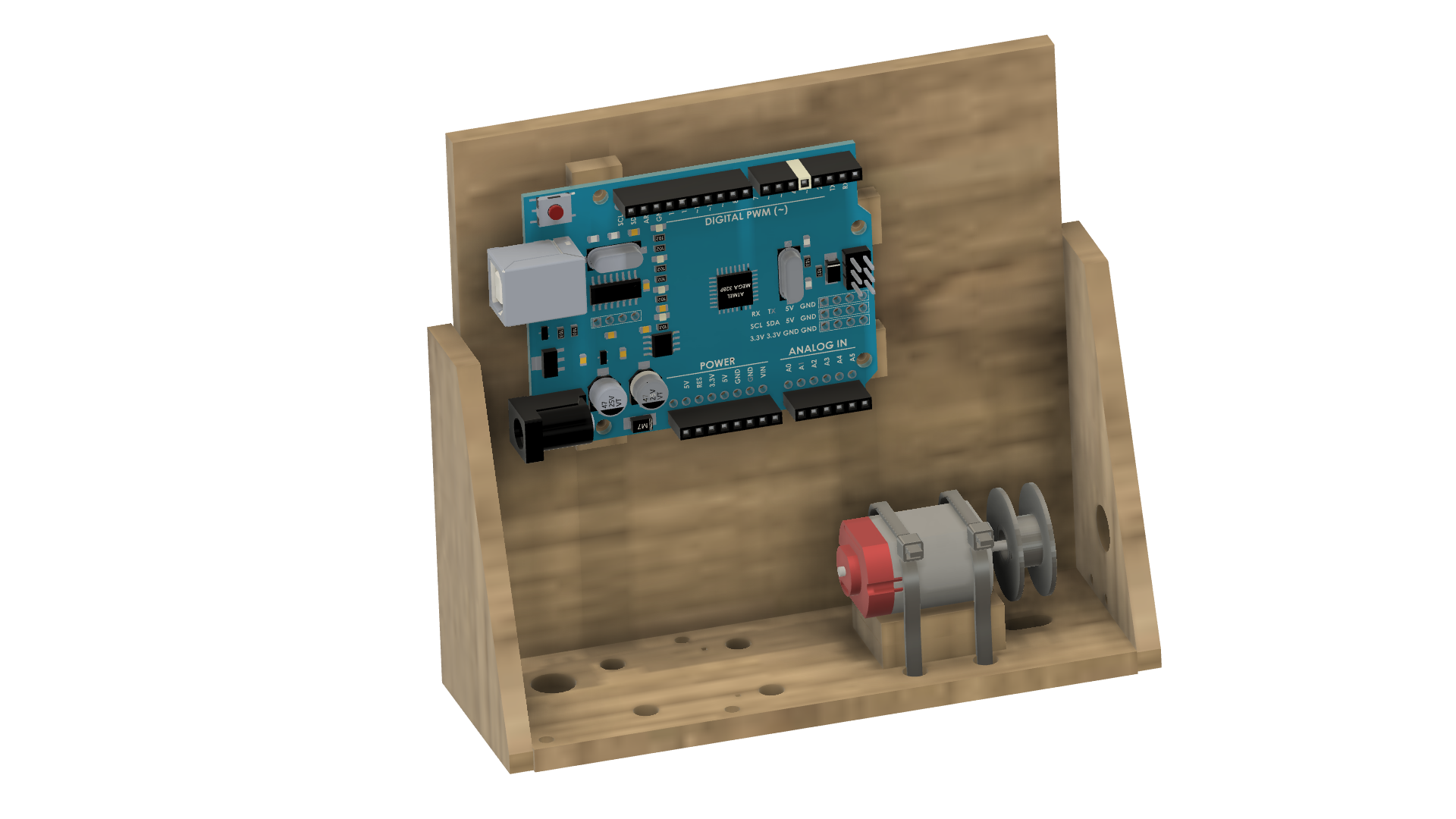
With the spool attached to your motor install the motor in the base of the chassis with two large cable ties. Make sure the cable clamp is by the motor not underneath.
![]()
-
6Wire the motor controller
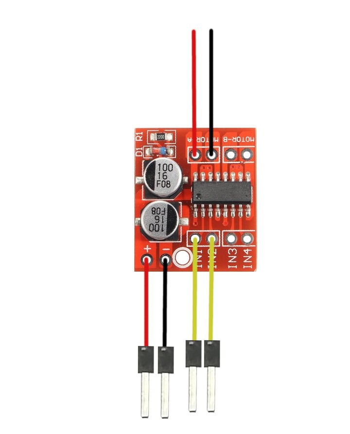
Prepare the motor driver for installation. The motor driver can drive two motors but we only need to use one for this project. Add a length of wire to each of the MOTOR A outputs. These will eventually be connected to our motor. Add a length of wire to the + and - terminals of the board. Then a length of wire to IN1 and IN2. Put a header pin on all but the motor wires to make installation easier later on.
![]()
-
7Install motor controller
The controller board doesn't provide too many mount options so we can just use some double-sided tape to attach this. Next to the Arduino.
![]()
-
8Prepare the paddle
The unit utilizes a paddle to tell the Arduino the spider has completed its journey. This should be made out of something flexible like plastic. I used an old ice cream container lid. Mark the paddle.pdf template out on a plastic lid and cut and drill the holes. For more details see the video here.
![]()
-
9Wire PIR sensor
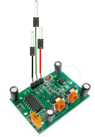
The PIR sensor has 3 connections Ground, 5V, and the signal wire. Attach a length of wire to each contact as shown below.
![]()
-
10Install the PIR sensor
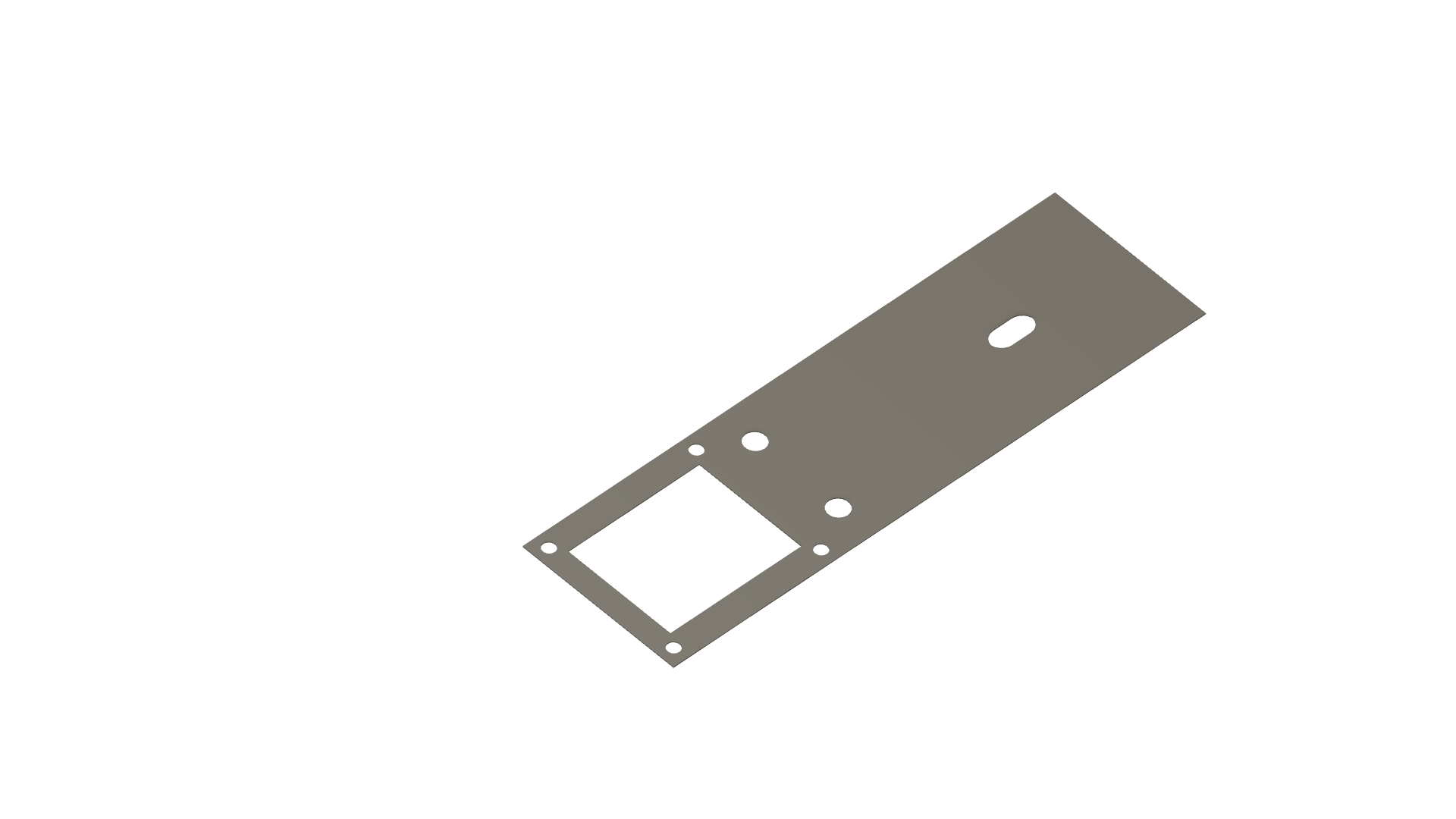
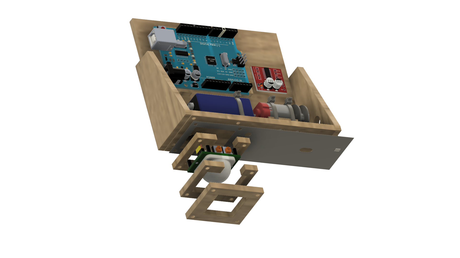
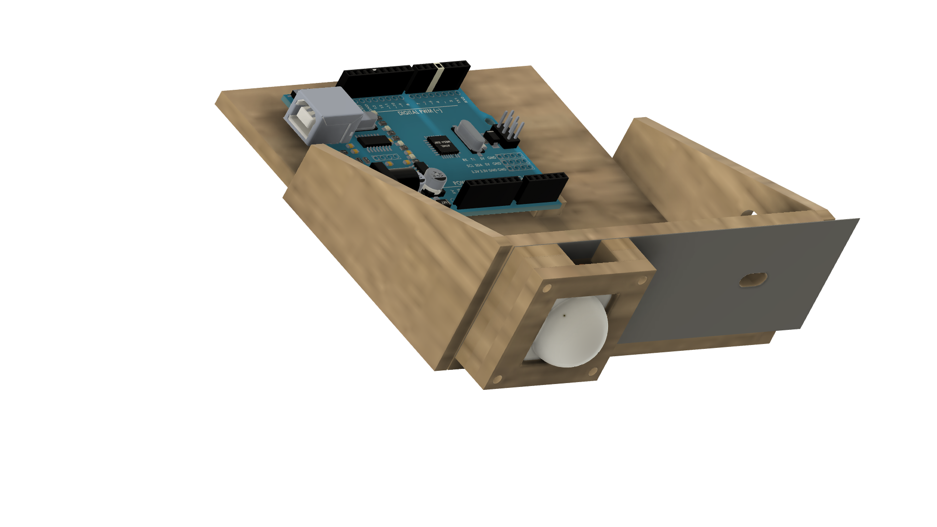
The sensor assembly is made up of 3 wood cutouts, the sensor, and the paddle. Place the paddle at the bottom of the chassis then the two cut-outs that align with the sensor screws then the base plate. Thread screws through all components and fasten with nuts. There is a large hole in the base for the sensor wirws. For more details see the video here.
![]()
![]()
With all the paddle components in place pull the cotton through the slot and tie on your spider.
Sensing spider prank (Wood Edition)
In this project, you will learn multiple aspects of Arduino while building an automated sensing spider.
 jasonwinfieldnz
Discussions
Become a Hackaday.io Member
Create an account to leave a comment. Already have an account? Log In.