-
Unusual PCBs
07/19/2014 at 18:29 • 0 comments
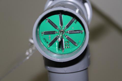
The PCB above is mounted inside of a 40mm T PVC pipe fitting. It is part of my weather station project, and gave me some interesting challenges to overcome in EagleCAD.The project called for an array of 8 micro reed switches, arranged in a spoke pattern around a central hole. Further, the whole pcb had to be circular to match the shape of the pipe. it also needed to hold resistors for each switch, a cable connector, and an IC. The hardest part is that the reed switches needed to be recessed INTO the PCB.
All while fitting in a space less than 48mm across (PVC pipe sizing is rather confusing, but that is another post).
as a point of reference, here is my original hand made prototype:
And here is the final PCB
Above: Installed in the pipe, reed switches facing out.
Above: Unpopulated
Above: The switches are mounted on the opposite side. Notice that the I2C expander IC is actually straddling the cutout of one of the switches. This side also contains the SMD resistors for each switch, and the cable. This face is against the bottom of the bearing seat plates, and can be glued in. I had to drill a hole for the cable in the bearing mount plates, which does not appear on the acrylic cut sheets.
When doing cuts like this, it is important to do so in the milling layer of the part. In addition, you need to include keepouts for top and bottom. There are other layers to deal with as well. The point is to assure that no traces and fills will span the cutout.
I have another project in the works that uses a similar method with wide pads to create metalized mounting slots. If they work out well (such as being plated through even with such an odd shape), I might try to use them as a bus connection through metal standoffs.
The board uses the PCA9534 IO Expander IC to hang 8 inputs/outputs of an I2C bus. I wrote up a simple Arduino example of how to configure and use the expander to read switch inputs and decode them to indicate wind direction.
- See more at: http://diy-scib.org/blog/very-unusual-pcb#sthash.urLrKvp3.dpuf
-
Acrylic Parts Files
07/13/2014 at 13:44 • 0 commentsFor flat materials, I have long been using CorelDraw. I began with it back in 1994, and have been loving it ever since. Recently I have been trying to use Inkscape more and more. However, as many of you know, Inkscape has some dimensional issues when working with laser cutters.
Typically, laser cutters use Corel as their go to application for import and cutting. Inkscape files imported in Corel are out of size.
So, in one small escape from totally open source, I have used CorelDraw for my acrylic files.
![]()
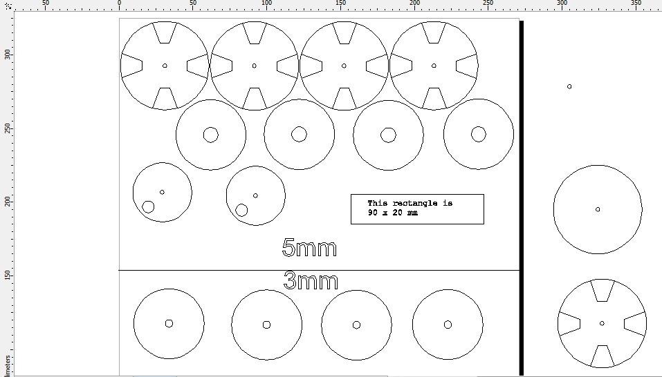
Top portion is to be cut with 5mm acrylic. Bottom 4 disks with 3mm. On the right side we have some spare parts.
Top row is the star disks which press fit to the top of the shaft, and the 50mm PVC cap press fits onto. Two per spindle.
Second row is the bearing seats. Two per spindle.
Third row we have the magnet disk (one per spindle). It press fits to the shaft, and a magnet is press fit and glued into the larger hole. I have since made disks with multiple holes for various magnets (experimenting), but have not included them on the official release yet. I am having better success with smaller magnets.
To the right of the magnet disks is a reference mark I always include in my files. It is a rectangular box of a known size, with text indicating as such. IT is VERY helpful to troubleshoot import issues when taking to a laser cutting shop.
On the 3mm side we have four bearing seat plates. These sit under or over the 5mm bearing seats. They serve to keep the bearings, and thus the shaft centered along its axis inside the spindle.
-
FreeCAD mechanical files
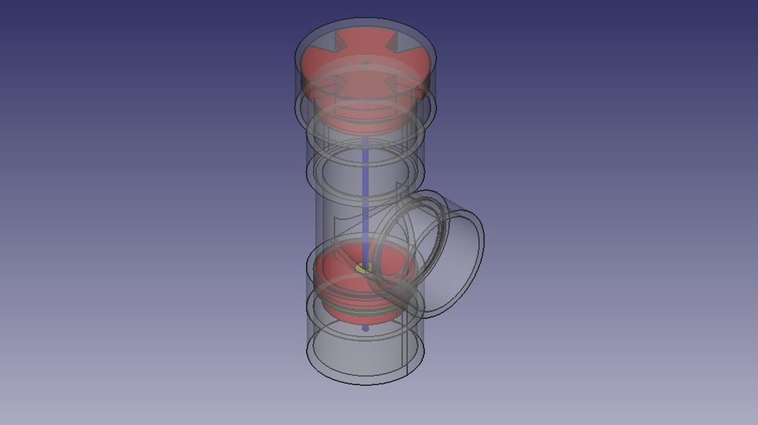
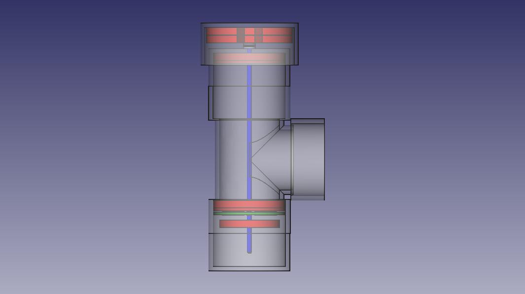
07/13/2014 at 13:13 • 0 commentsI dug out my FreeCAD drawings and made images of the drawing. I am adding those images now, and will link the mechanical file. You can open it in FreeCAD, explore the mechanical design of the spindles, find the parts and make your own modifications.
![]()
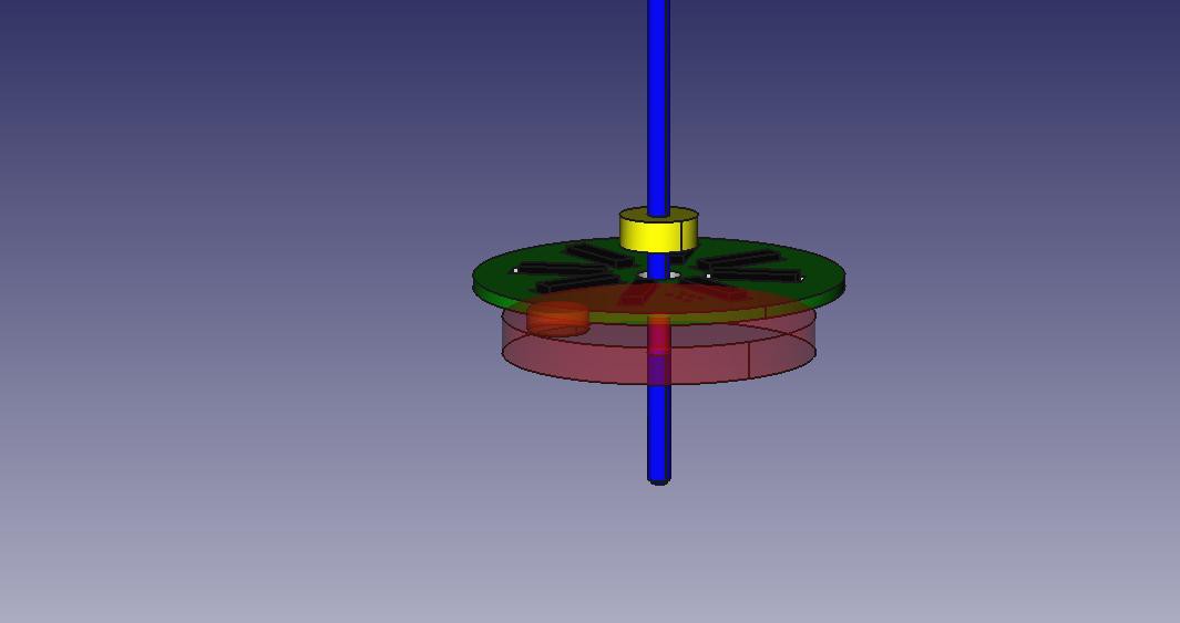
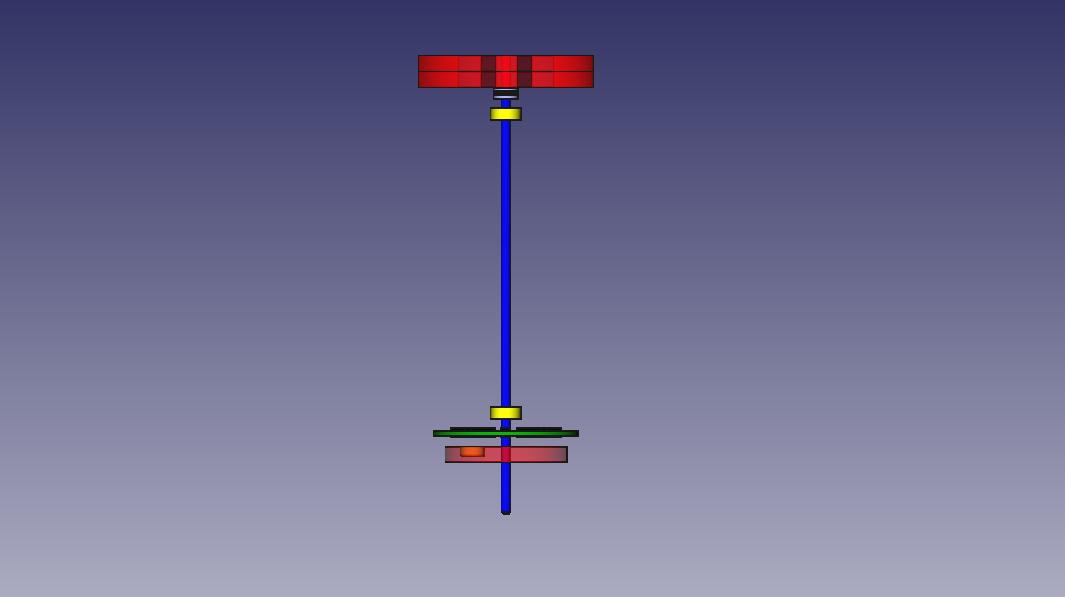
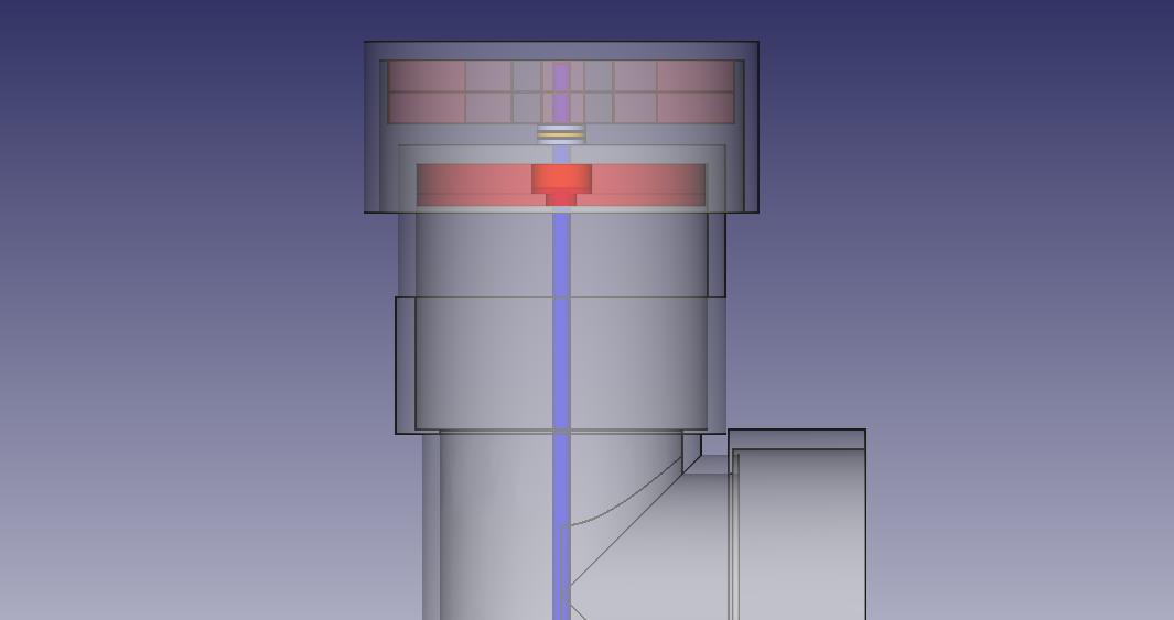
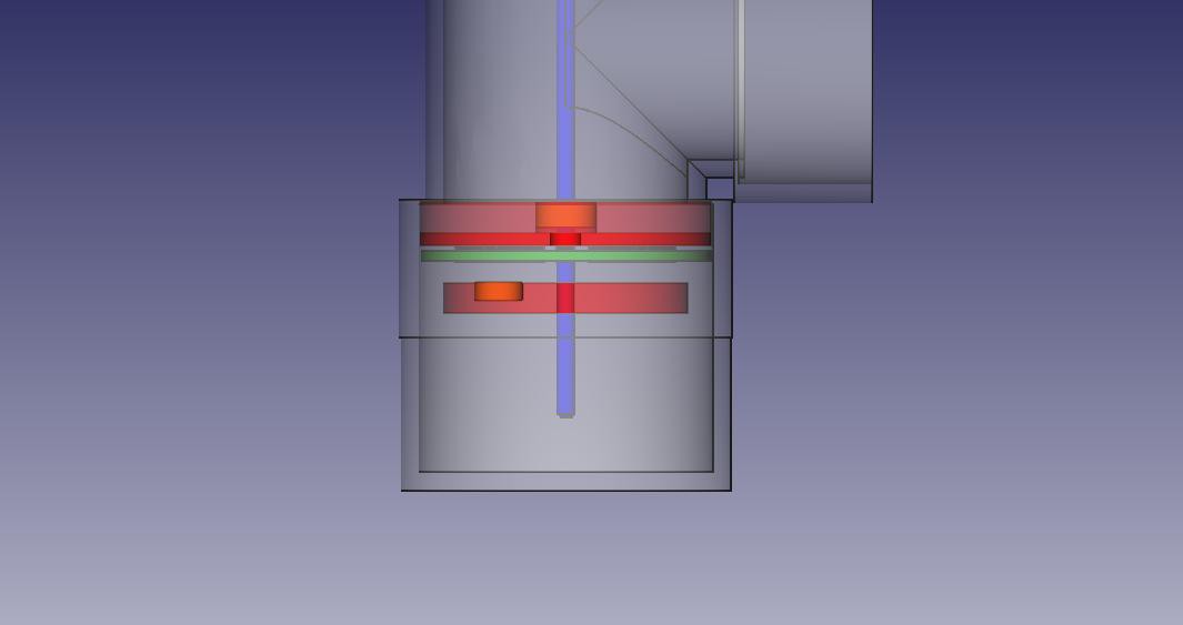
The green PCB holds 8 micro reed switches, surface mount resistors, and a 8 channel digital I2C expander IC. The saft (blue) rotates in a set of two bearings (yellow). A magnet (orange) is held by an acrylic disk (red) which is press fit to the shaft. As the magnet rotates, it pulls the reed switch/s nearest it closed. This wind vane PCB with 8 switches has a resolution of 16 directions, since two adjacent switches may be pulled closed by the magnet.
![]()
Both bearings (yellow) are held in place by a two part acrylic disk bearing seat (red). The centering disk is 5mm thick, to match that of the bearing. It's center hole is cut to the outside diameter of the bearing. The base disk is 2mm thick. It's center hole is cut larger than the shaft, but smaller than the outside diameter of the bearing.
![]()
![]()
![]()
![]()
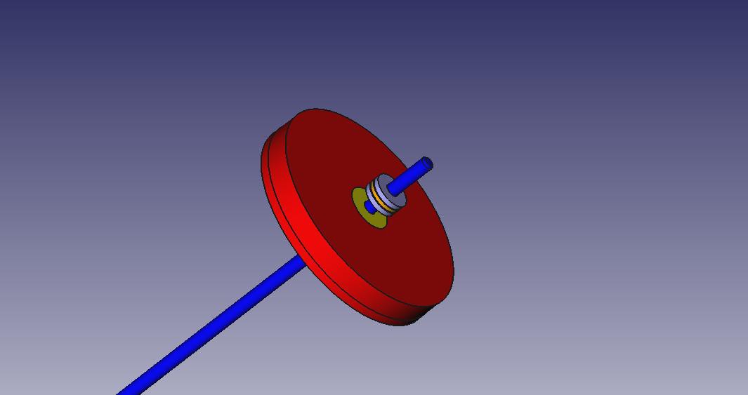
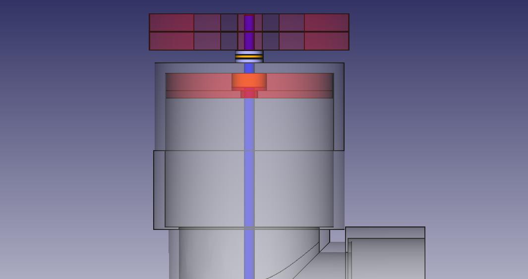
Two 5mm "star disks" are press fit to the top of the shaft. It is the 50mm PVC cap that press fits over these the drives the shaft assembly. Between the star disks and the spindle main body is a thrust bearing (silver-orange-silver).
![]()
The 50mm 'hood cap' overhangs the 40mm cap
![]()
, preventing wind from blowing dust or rain into the space above the top of the spindle body, thus keeping the whole assembly clean and dry. It is to the 50mm cap that arms are attached for wind cups, or a vane and weighted point for a wind vane.
The next file on the way will be the laser cut acrylic files. -
Current state of the project
07/12/2014 at 15:49 • 0 commentsWhat is complete?
- The largest hurdle, the mechanical aspects of the spindles for anemometer and wind vane are complete.
- Reed switch board is complete and tested.
- Mast assembly completed.
- Preliminary code testing of anemometer, used to begin deriving the relationship of rotation speed to wind speed functional (just your standard 'wheel speed' program)
- Wind vane code for talking to the I2C expander on the reed switch PCB complete, outputs human readable wind direction
- Most of the sensors I plan to use have already been coded and proven on various other projects
What still needs to be done?
- Interface board to carry the Arduino, RS232 interface, regulators and sensor support circuitry needs to be designed.
- Remaining sensors need to be integrated to the mast
- All outdoor electronics need conformal coating
- PVC needs 'final install' gluing, or perhaps link pinning, such that I can still disassemble it.
- Arduino code needs to be integrated
- I have not even touched the head end yet. For my first version I will just use processing to snag data, parse it and log it.
Can I actually accomplish the items on the above list?
- I have designed plenty of Arduino shields in the past, and already have most of these circuits either in Eagle, on paper, or in my head. Its just a matter of sitting down and doing it.
- Integrating sensors into the mast is a mechanical challenge. The only disadvantage to using size 40 pipe is that the exposure area for sensors is small and circular, making for a high density space. I will likely put all the sensors on a disk board which hangs out the bottom of one the T which also holds the Arduino and support boards. This one will take time, but nothing here is out of my league (confident with the tools required). Just takes time.
- Conformal coating is a trip to the appropriate shop, some cash on the register, and a can in my bag. Not worried about that one at all
- Final 'locked in' assembly is just either gluing the PVC or drilling holes for pinning/bolting. Again, no problems there.
- Integrating the sensor code is just time consuming but not hard. Most of my sensors I already have libraries for. Also, I have proven out this sort of system with the seismometer project in my book "Arduino Projects to Save the World."
- My big challenge is in the head end. I don't work with Linux much, nor Raspberry Pi (have one but have yet to use it). However, in the above mentioned book, I have demonstrated how to read data, parse and log it using processing. I can at least get that far without any trouble. I will have to teach myself about web servers though. This is unlikely to be finished by the time the first round of eliminations.
Modular Weather Station
A collection of low cost and hand built weather sensors for personal and educational use, posting data online.
 diysciborg