-
Mane fabrication complete
10/31/2022 at 23:08 • 0 comments![]()
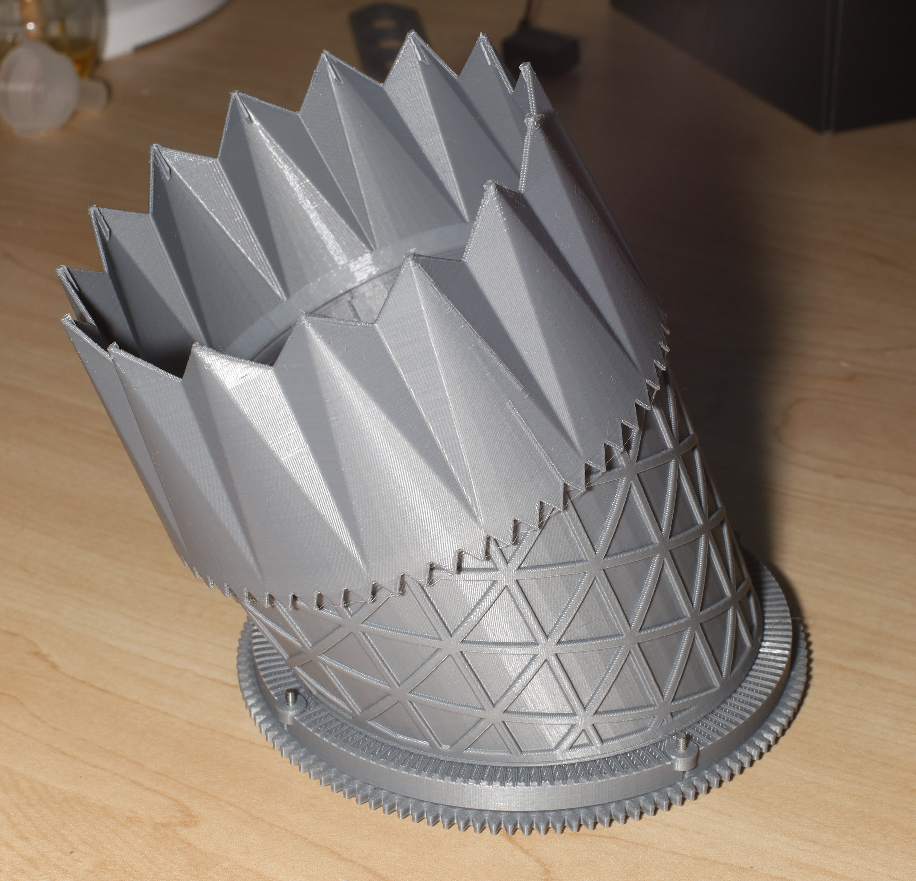
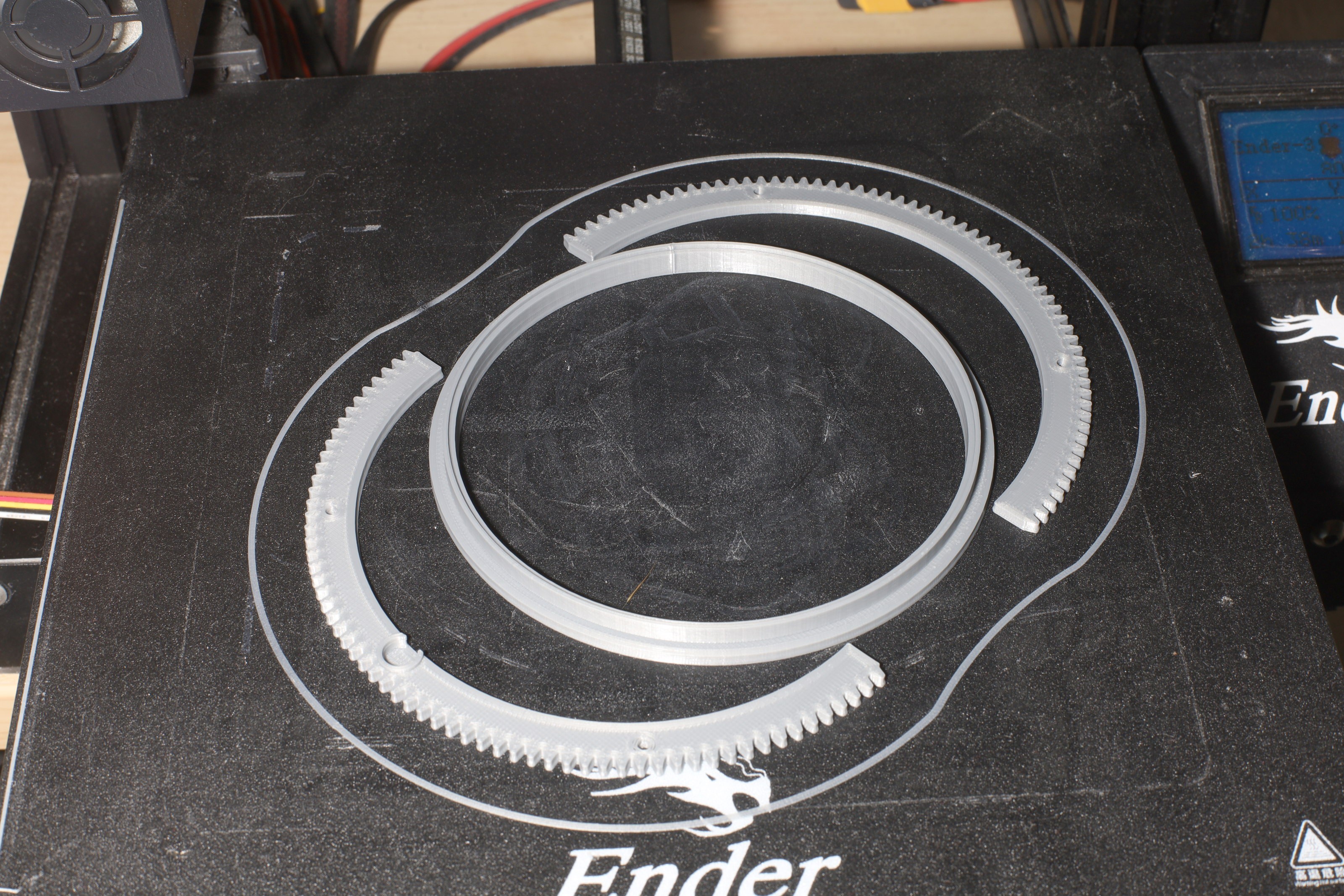
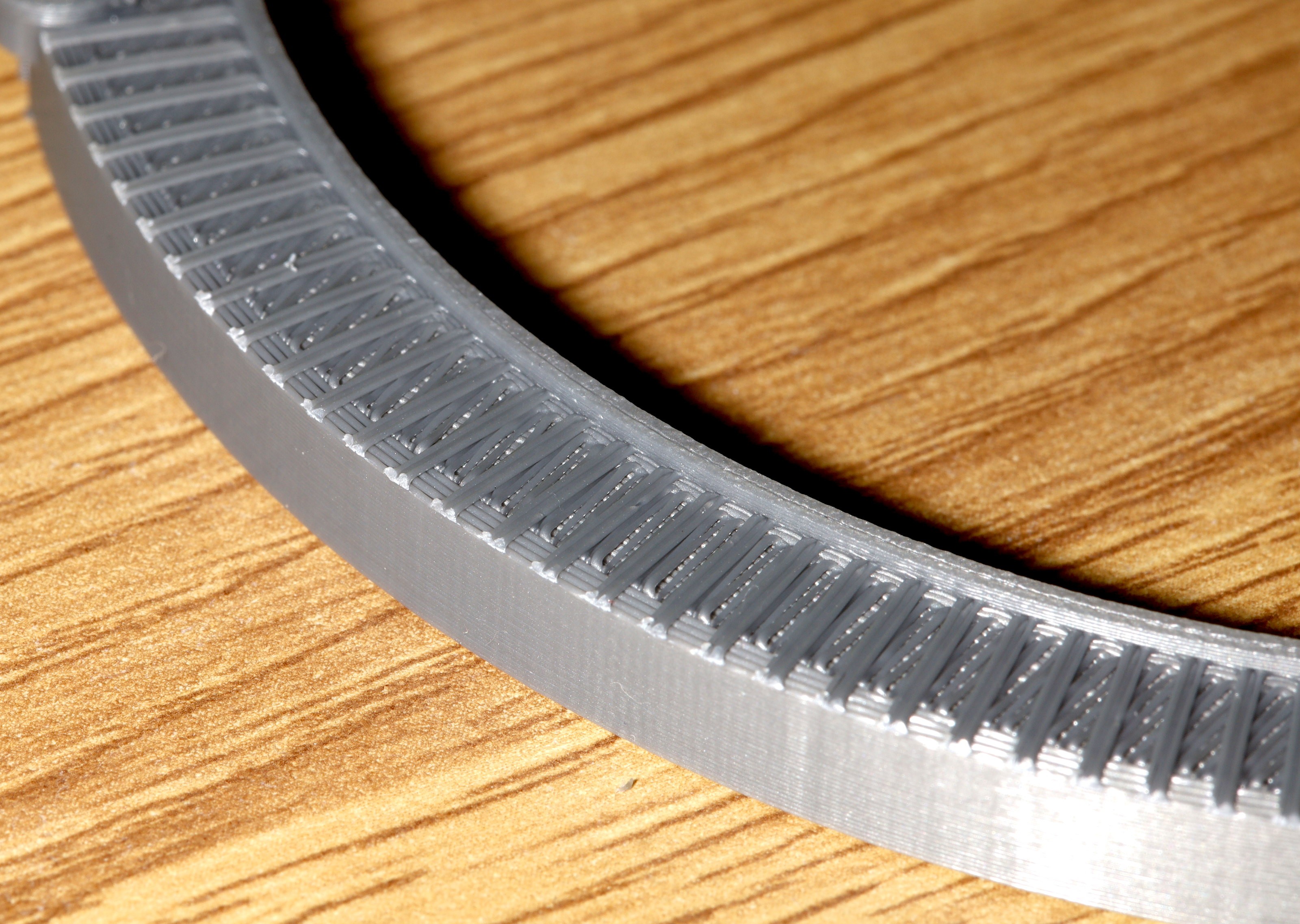
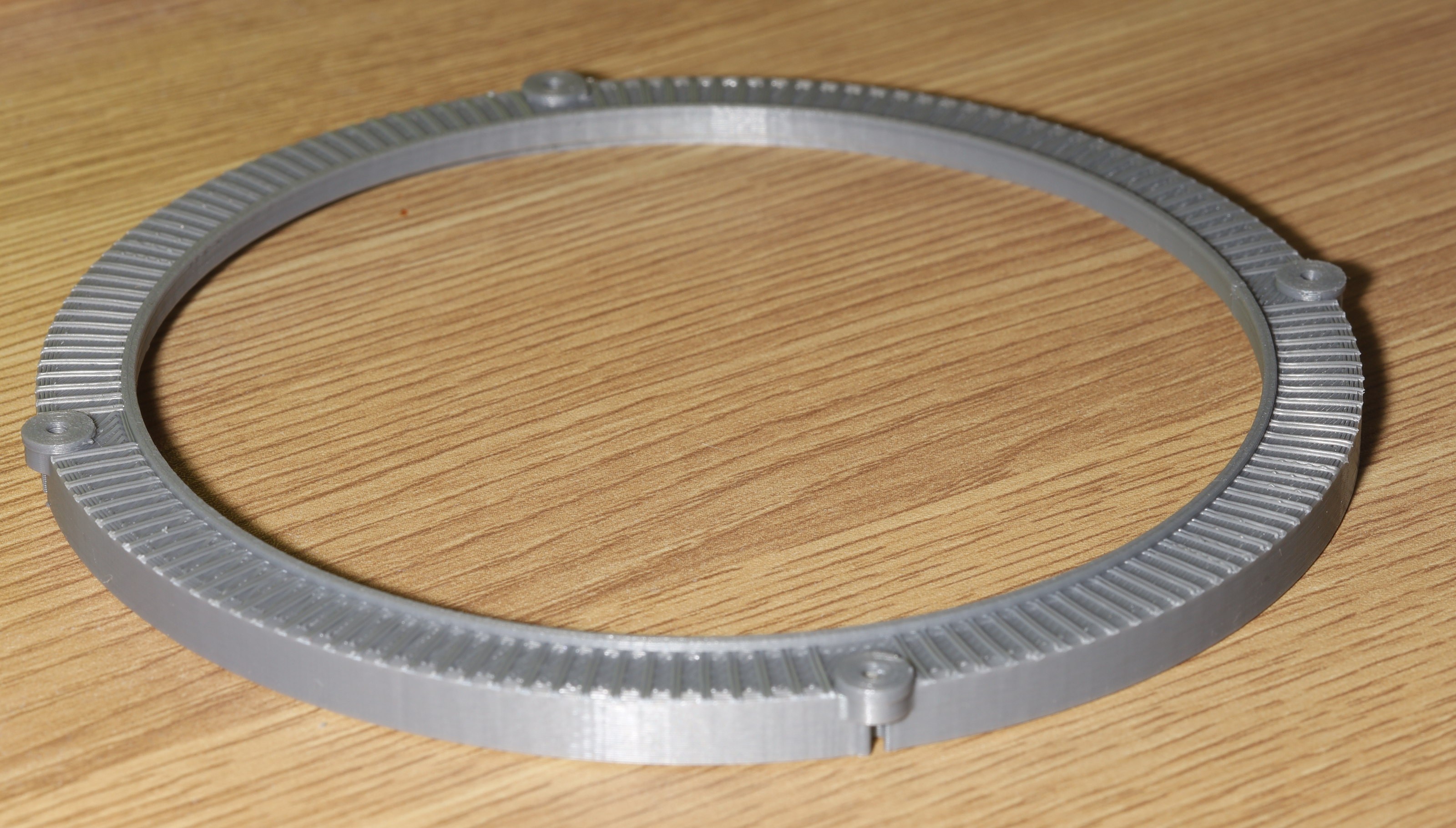
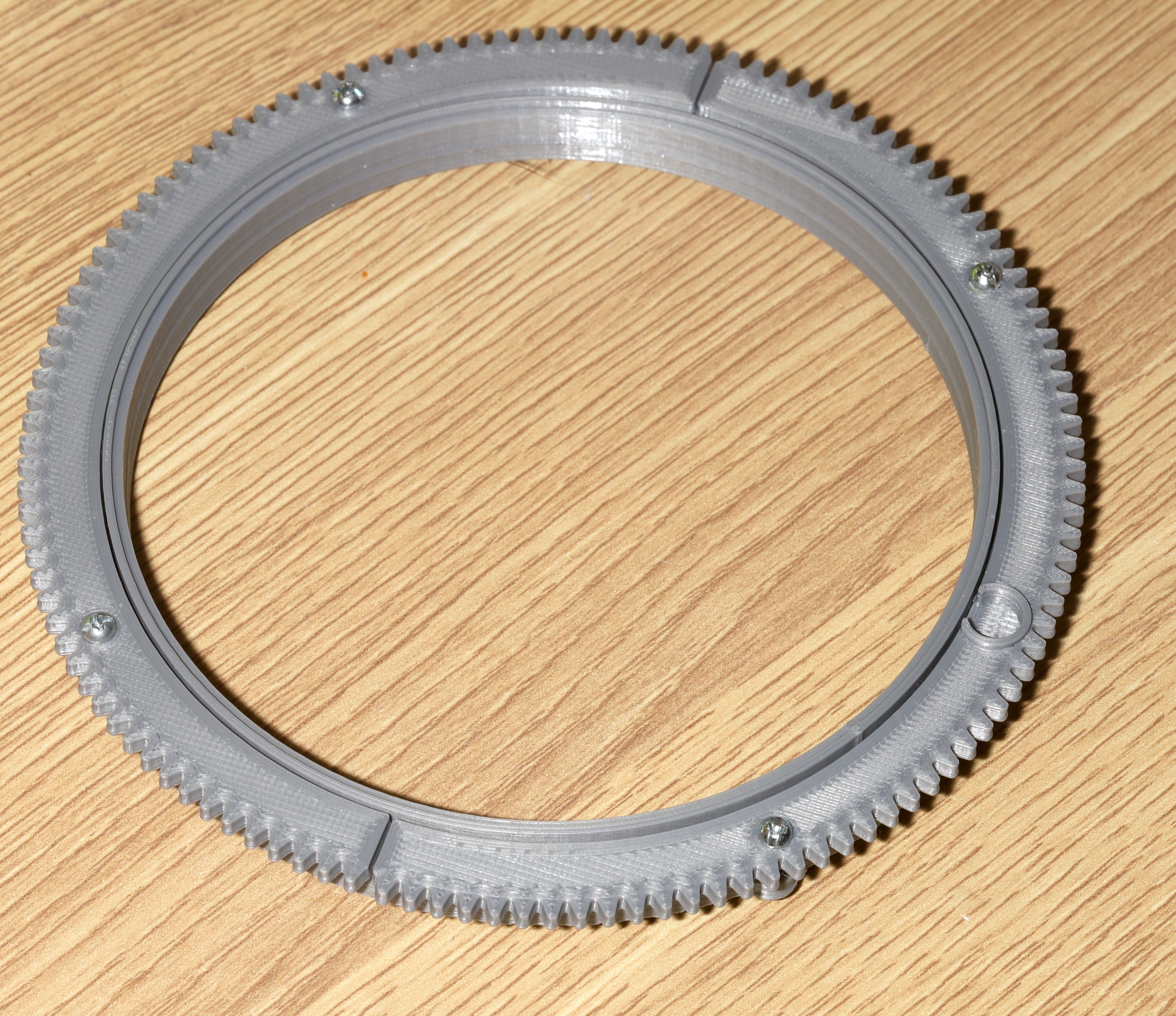
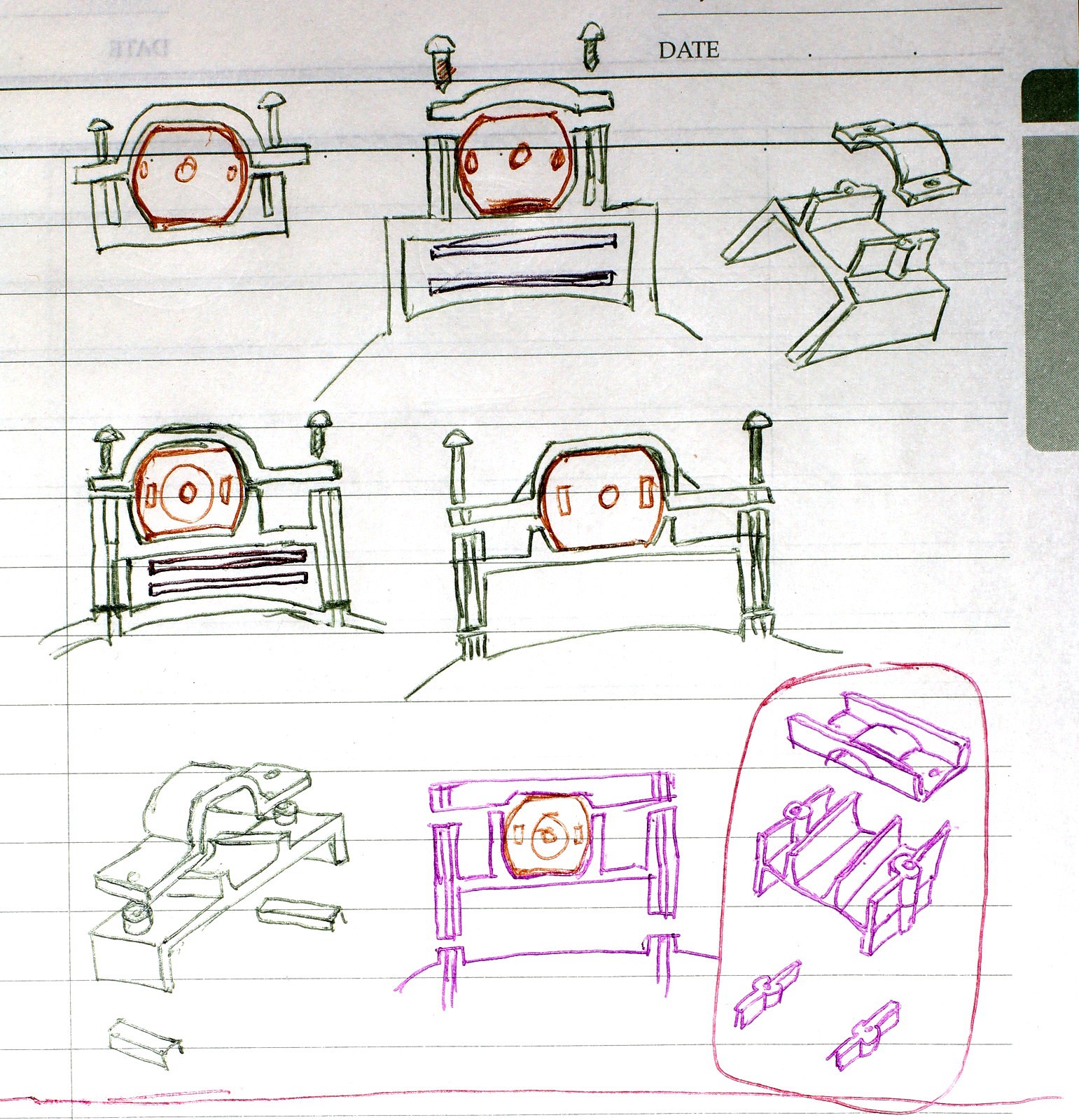
The mane components came out over 3 days. The motor mounts evolved during printing. The mane regret is how wide the motor mounts had to be to house the board connectors. Surface mount connectors would have been smaller but required expensive ribbon cables.
![]()
The motor mounts were properly booleaned so nothing sticks into the bore.
![]()
![]()
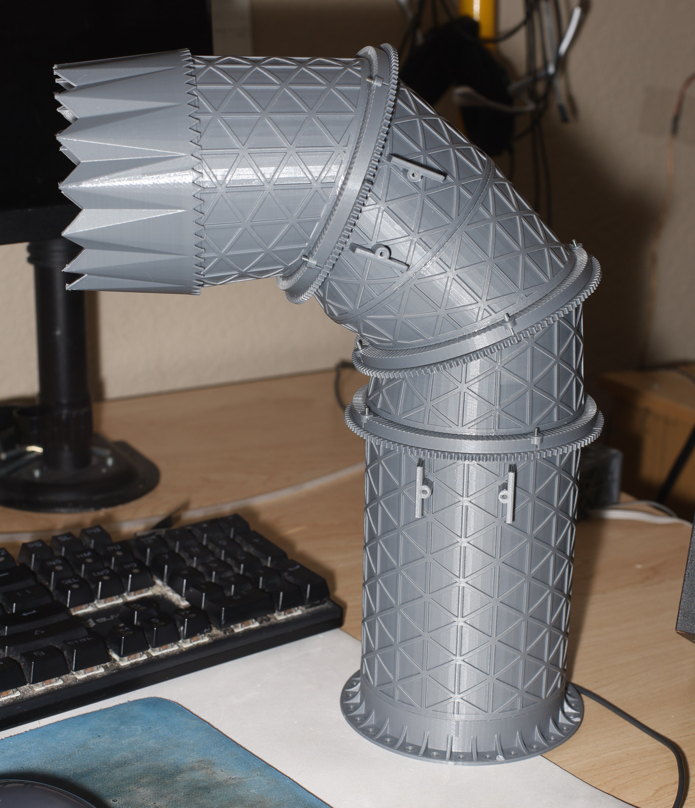
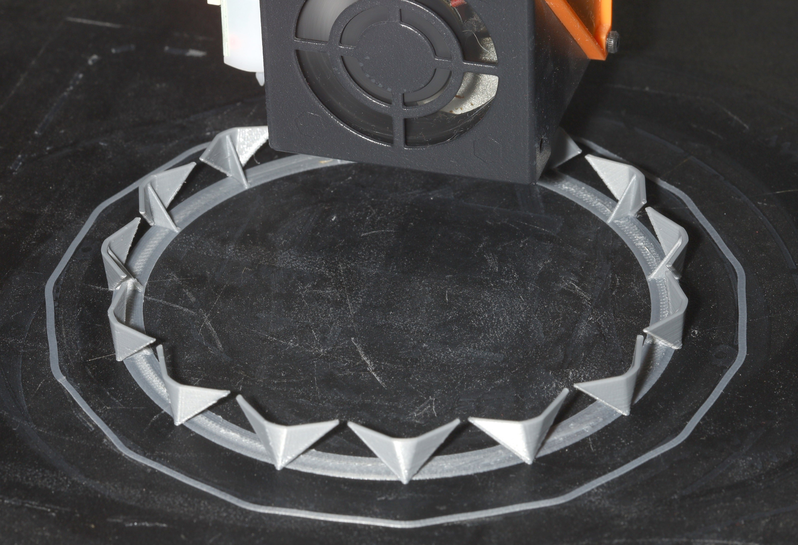
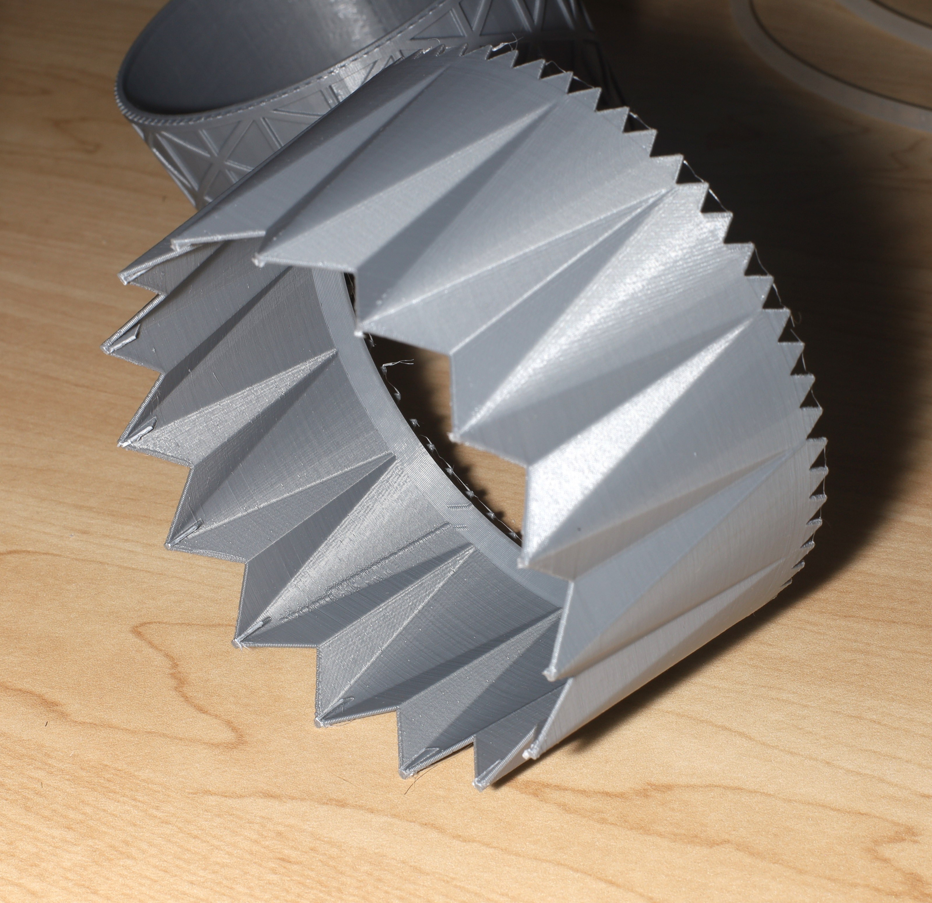
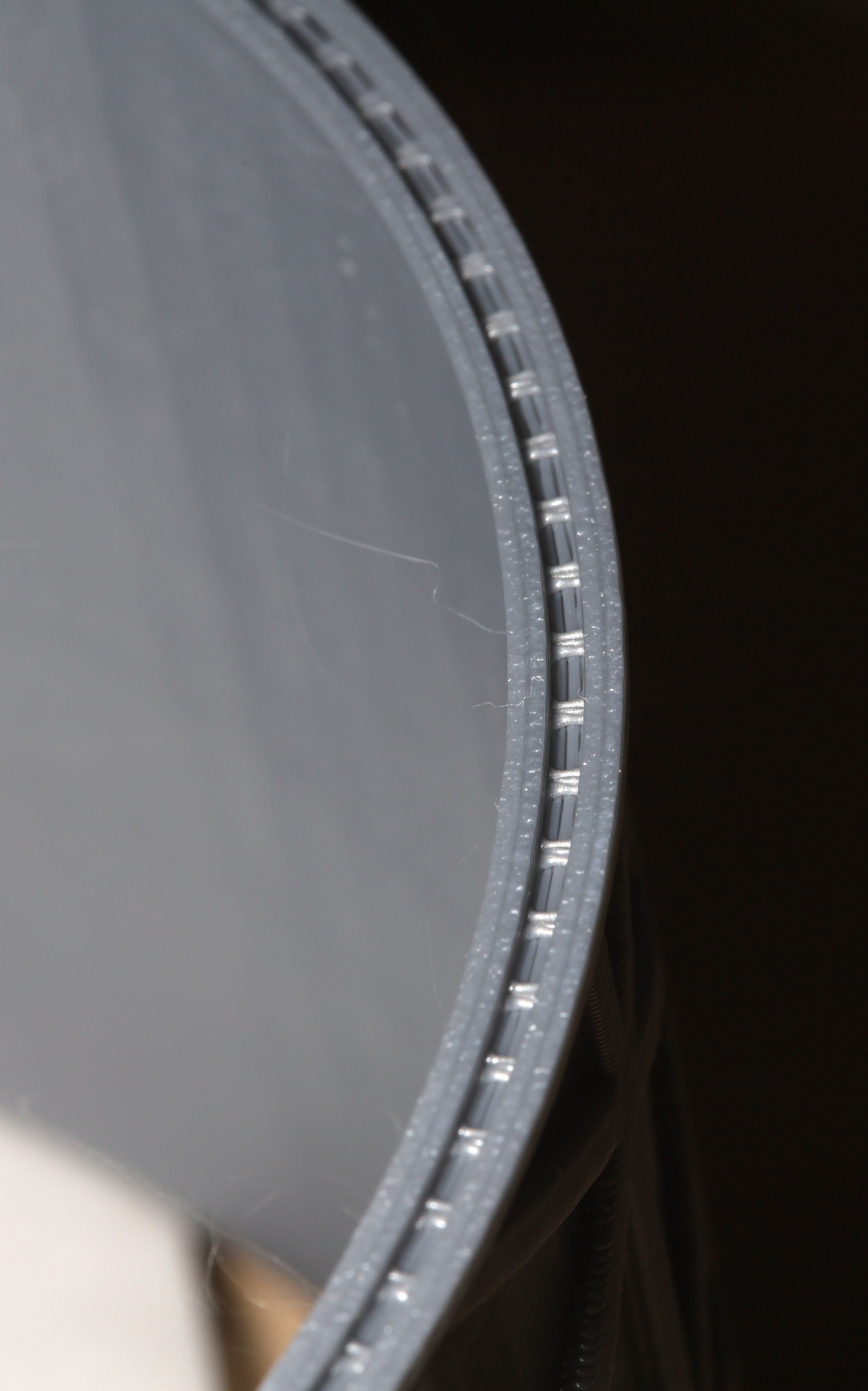
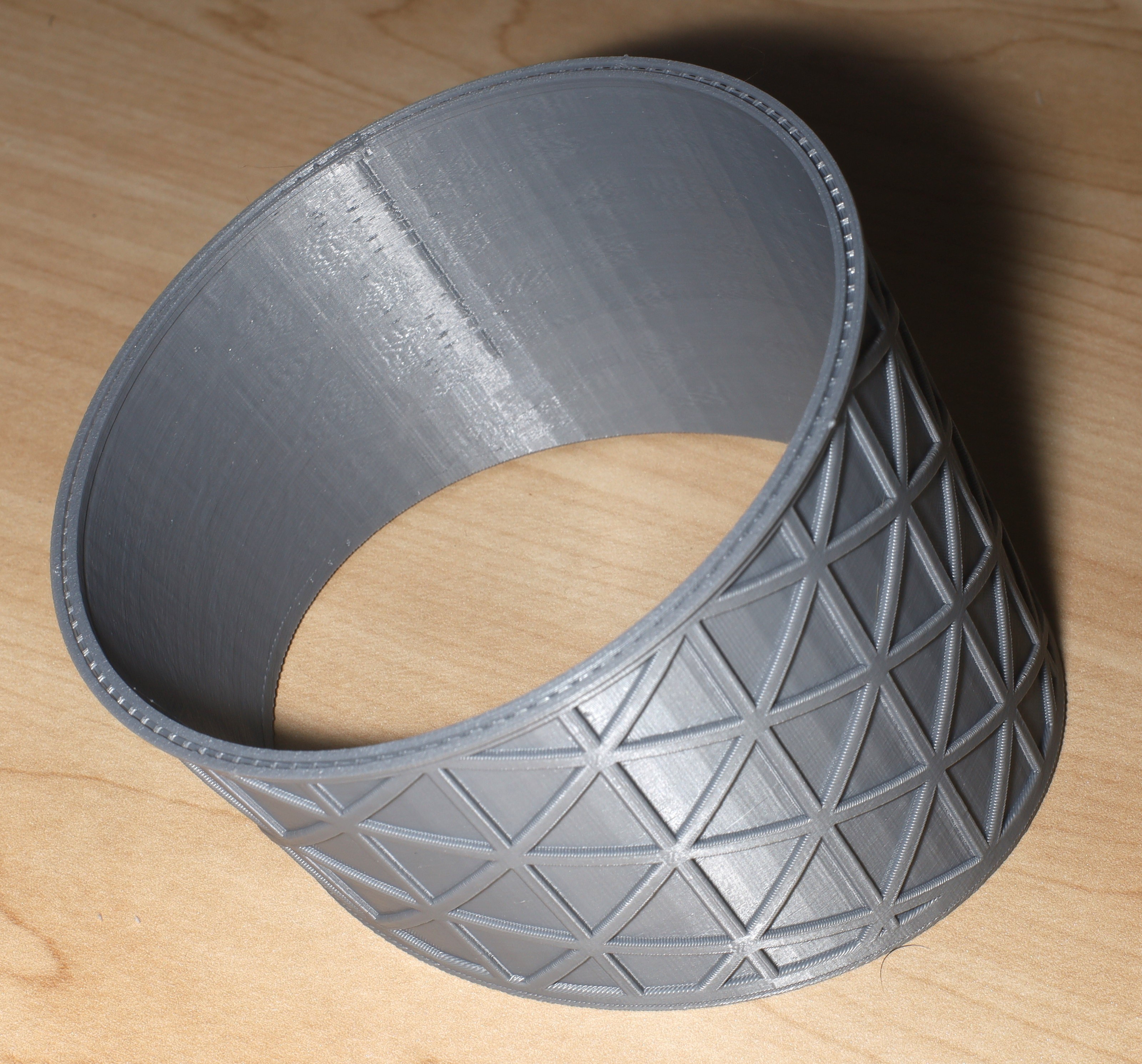
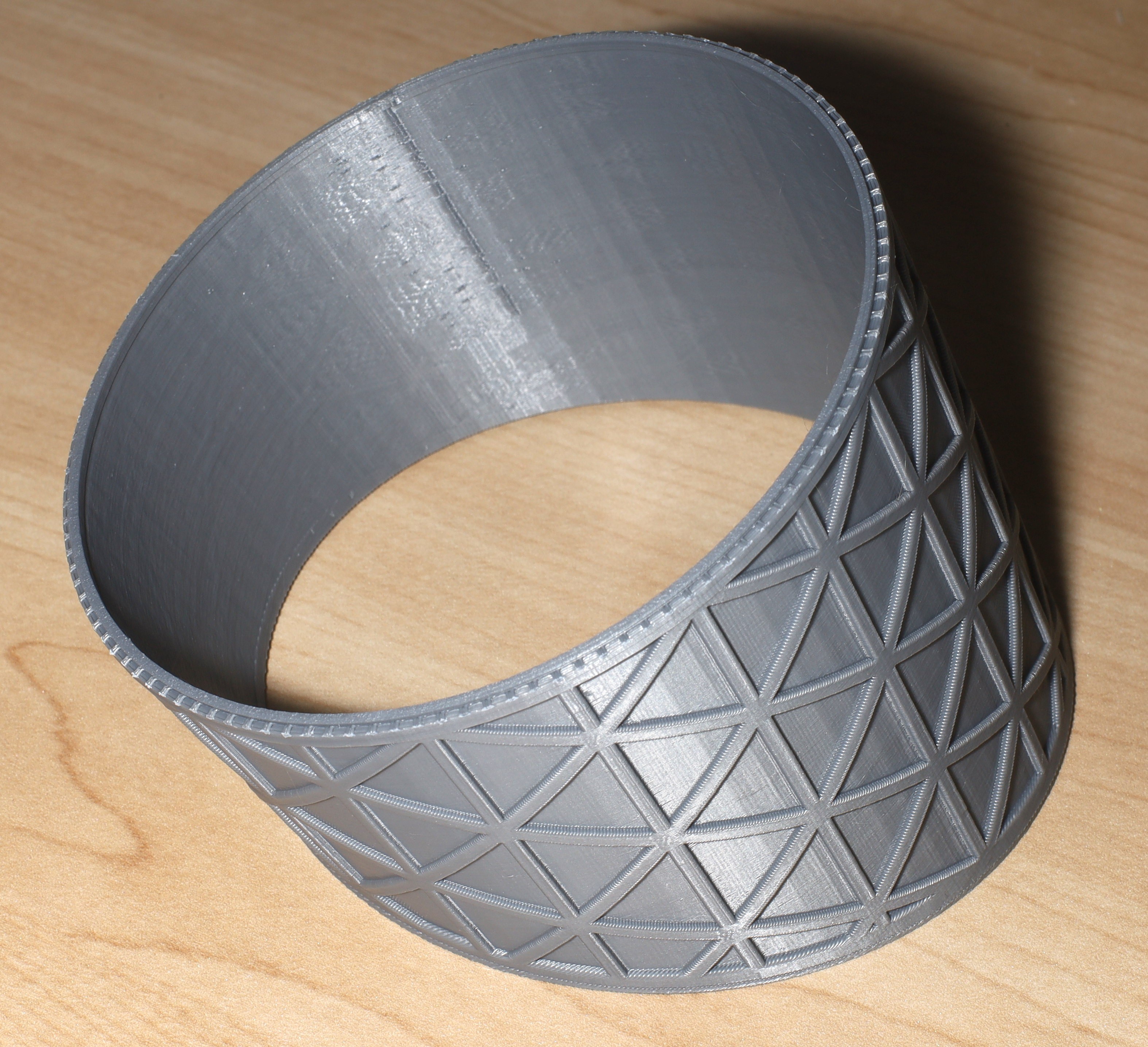
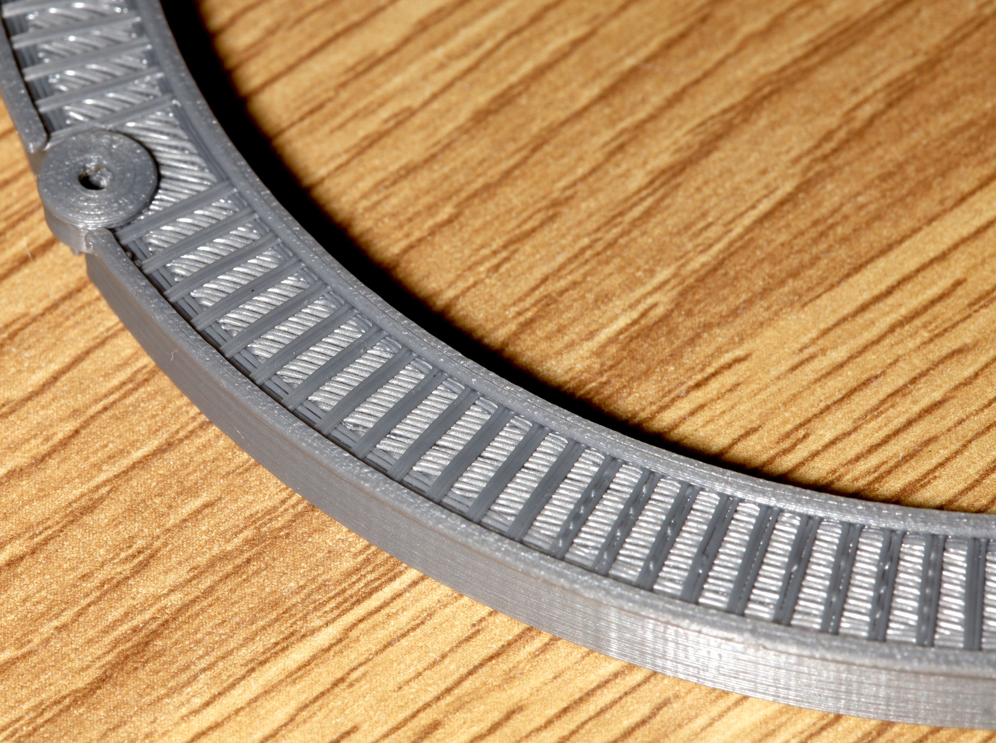
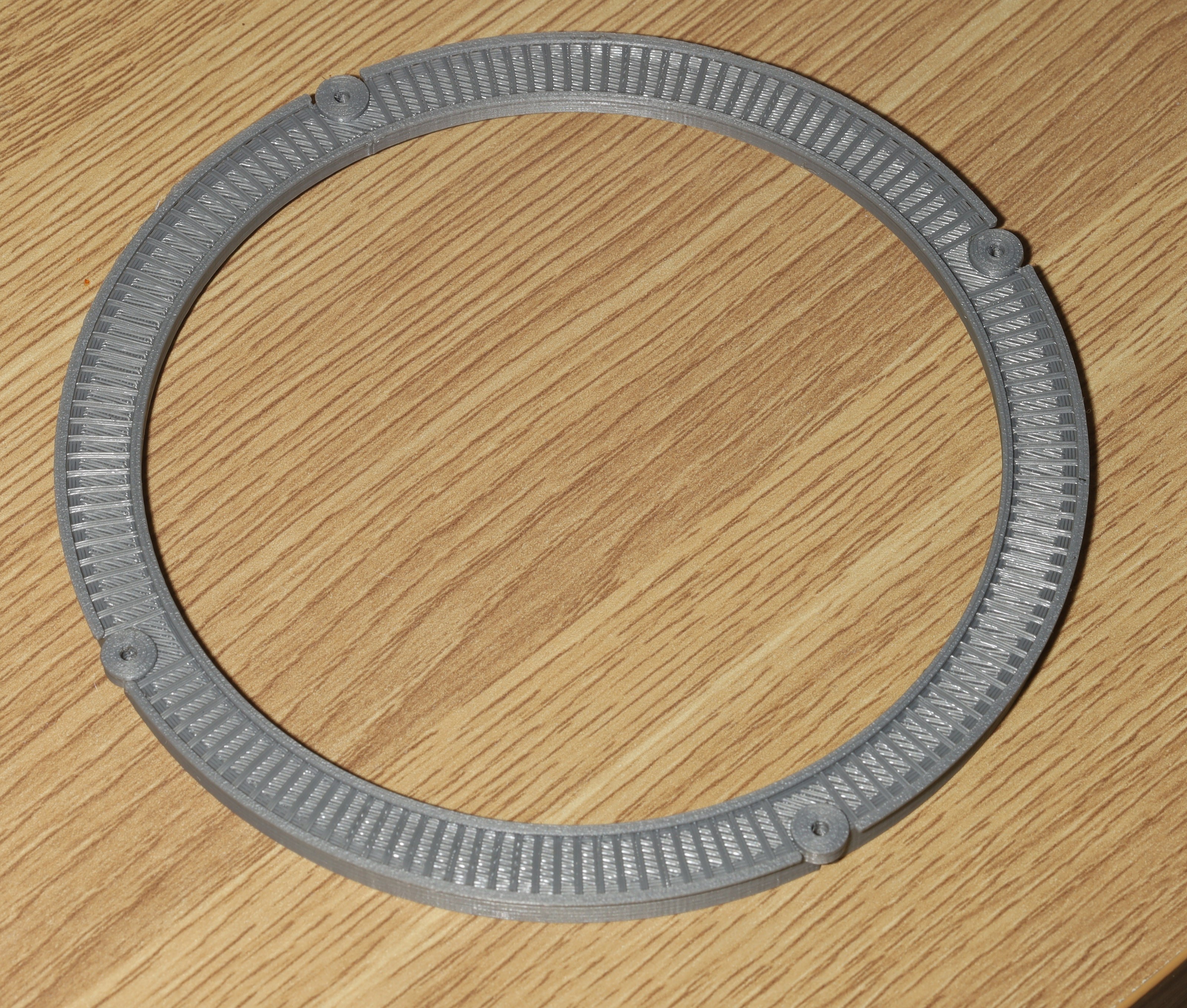
The big piece took 16 hours. No obvious evidence of the gantry sag.
-
Death of atmega
10/30/2022 at 18:44 • 0 commentsThere was a desire to have the boards all programmed over single wire UART. The bootloader support on the Atmega328 is described on page 267. Step 1 is programming the BOOTRST bit to make it boot from a bootloader address instead of 0x0000. The 4 possible bootloader addresses are given on page 277.
There's no need to indirect the interrupt vectors. The IVSEL bit in MCUCR relocates the interrupt vectors to the bootloader address.
It's actually impossible to write to flash from a program running outside the bootloader section. This is a contrast to the PIC which can write anywhere.
The 1st thing lions noticed is the Atmega328 always ignored the value of BOOTRST, would not run anything in bootloader space & only ran programs at 0x0000. The internet said the program counter was jumping over opcode 0xffff & looping around the memory until it hit the 1st program. After much playing with this, the chip eventually bricked. A corrupted DWEN bit, RSTDISBL bit, or clock source bit is the leading cause of bricked atmegas.
The lion kingdom has an Atmel ICE in which the debug menu has a "disable debugwire" option, but it requires adapting a 10 pin connector to the RESET pin. Helas, Atmel studio only showed a debugwire failure.
An atmega88 scavenged from an RC transmitter similarly failed to program. It's believed the atmega328 was bricked because it was soldered when it was live. The atmega88 might have had ISP disabled in the factory. High voltage programming would be the next step in restoring any of these chips in any case.
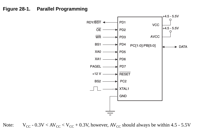
High voltage programming of the atmega is also called parallel programming. There is a big old schematic on page 286 showing what it entails.![]()
A new board would have to be made & the TQFP would have to be resoldered so it's basically a brick. There would be a finite number of resolderings before a home made TQFP board wore out, but maybe a bunch of TQFP boards could be made.
Despite once being the world's most popular chip, the atmega328 is incredibly prone to bricking compared to a PIC. It was end of lifed in 2020. The lion kingdom has a few left from 10 years ago, when they were sold in packs of 10 for pennies. Most of them have been bricked.
After burning several days on a bootloader & trying to recover dead chips, the decision was made to abandon the bootloader, just have temporary programming headers on the motor controller boards & a permanent header on the brain board. 2 boards are just dumb motor controllers taking in H bridge commands & sending encoder counts.
An AVR bootloader is much more involved than a PIC bootloader & involves bricking many chips. The best strategy for a bootloader is to use 2 arduinos to burn bootloaders on each other, capture the flashing commands arduino uses, & modify the arduino bootloader for a single wire serial interface.
Whether or not they were ever made again, the lion kingdom would not use atmega328's in the future. It's such a pain to use multiple architectures & development environments. The only reason anyone does that is to pass job interviews.
-
Structural printing begins
10/28/2022 at 23:28 • 0 comments![]()
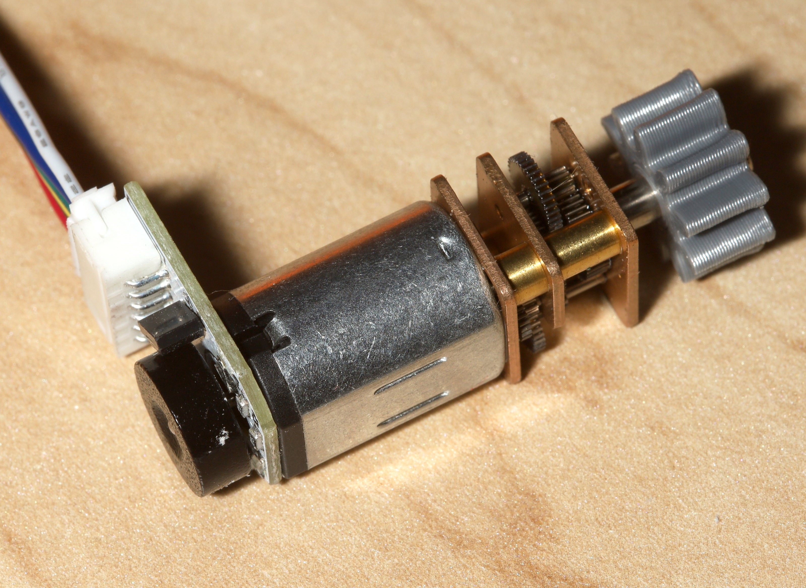
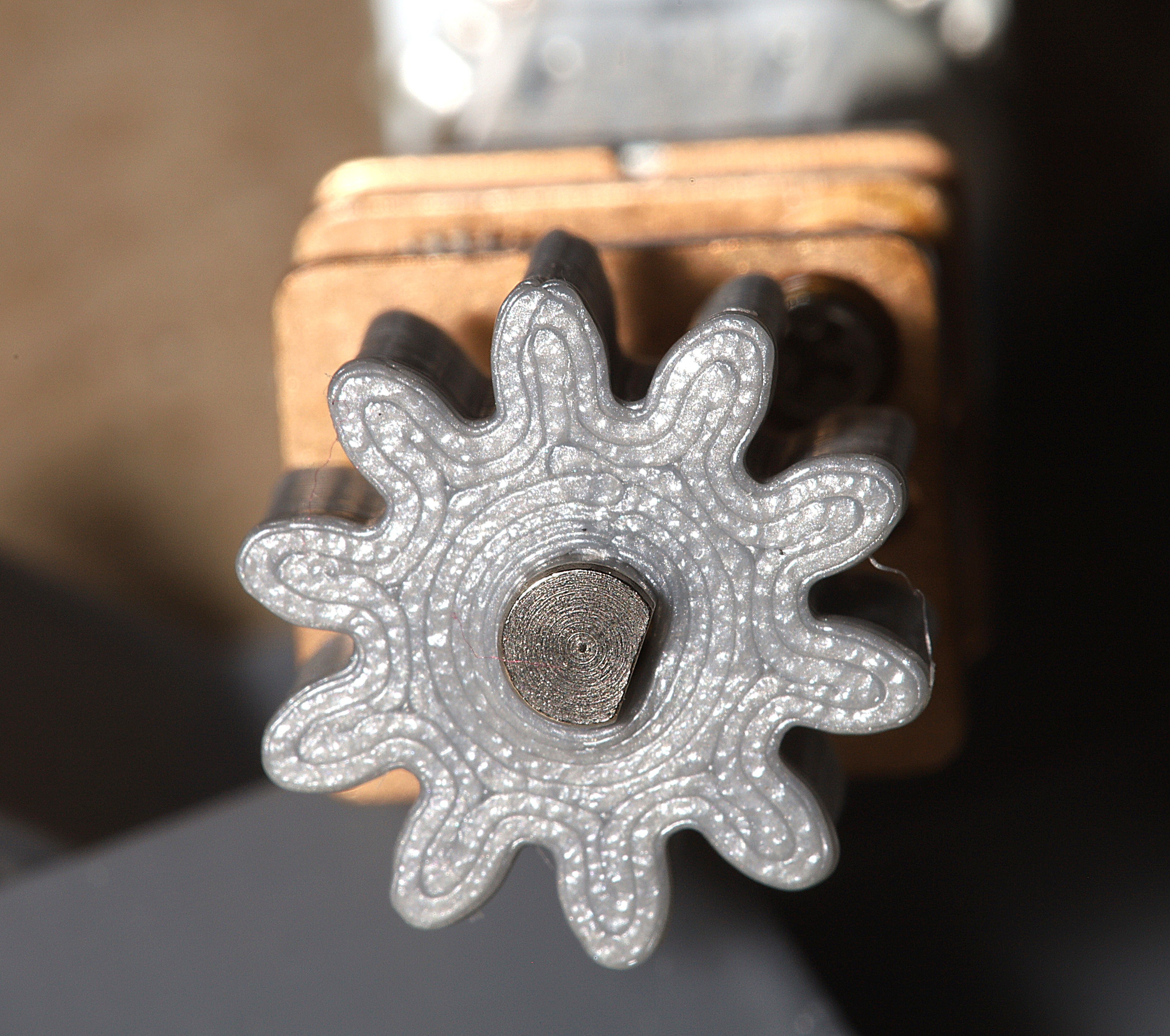
While press fitting the gears on, it became clear that the encoder wheel is very easy to press into the circuit board, rendering it immobile. The gear has to be heated to press on, but can't be pressed on by force against the encoder wheel. This probably requires a new tool, but for now the outside of the motor is the only place to grab.
![]()
The 300:1 gear ratio now requires powering the motor to move it.
![]()
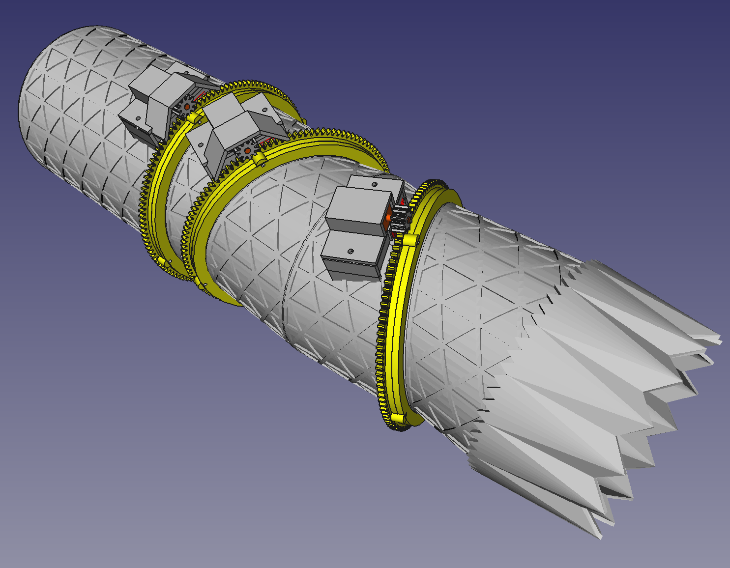
The updated motor mounts were laboriously put on the tube segments. Models & supports were updated with new techniques. Passed on adding wire harnesses to the tube segments. It might be easier to put wire harnesses on the motor straps.
![]()
The 1st structural print was the exit nozzle. A new support method was tried.
![]()
![]()
These supports could be clipped out but left ugly bits on the inside.
![]()
New bearings were complete. The magnets ended up not the same polarity.
![]()
The 1st tube segment was printed. The isogrid pattern is hard to clean, but the decision was made to keep it.
![]()
![]()
![]()
![]()
New support method was much easier. There were still blobs near the Z seam which had to be scraped out.
![]()
The exit nozzle fit together.
-
The common control board
10/25/2022 at 04:03 • 0 commentsTo allow quadrature encoders & all the extra signals on each motor, the new nozzle has a dedicated control board for each motor, with a single wire UART stringing them together. 2 boards are dumb motor drivers which read H bridge bits & write hall effect sensor values. 1 board is the brain board. All 3 share a single UART wire.
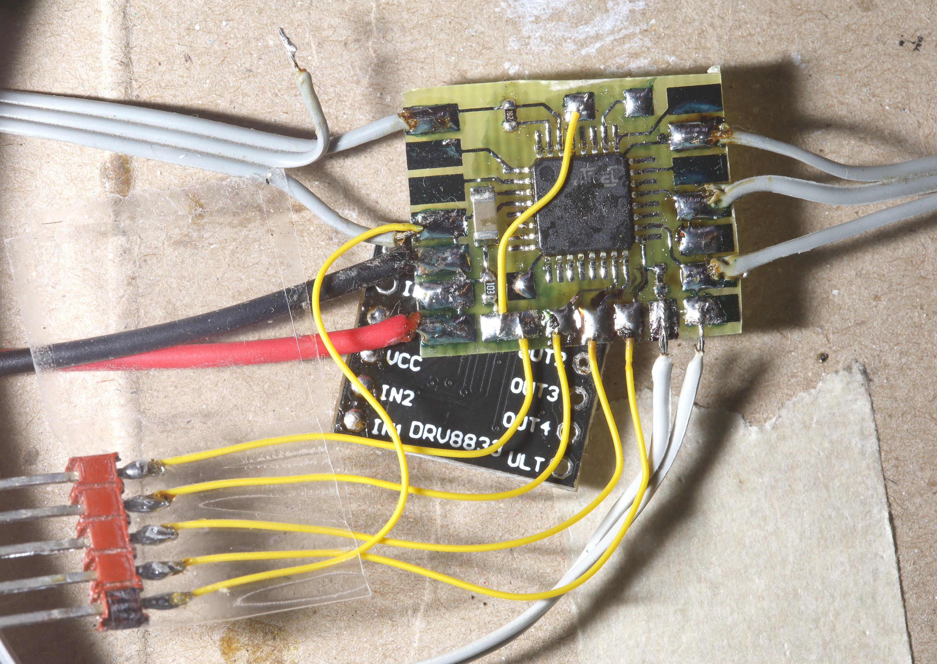
A quick mockup showed a new board with the DRV8833 & the ATmega328 side by side would take more space than the DRV8833 breakout stacked under the Atmega328. Without stacking, they wouldn't even fit on the nozzle. The stack would fit neatly under the motor. The breakout board also does a better job connecting the ground pad of the DRV8833 than a home made board can do.
![]()
Testing showed the IR parsing could work in its internal 8Mhz oscillator by assuming all the IR codes are the same length. Who knew 5 years after the lion kingdom's 1st IR parser, there were still optimizations to be had.
There is a definite lean towards a bootloader to reduce the wiring. It would entail custom hardware to drive the single wire UART & indirecting the interrupt handlers does not appeal.
![]()
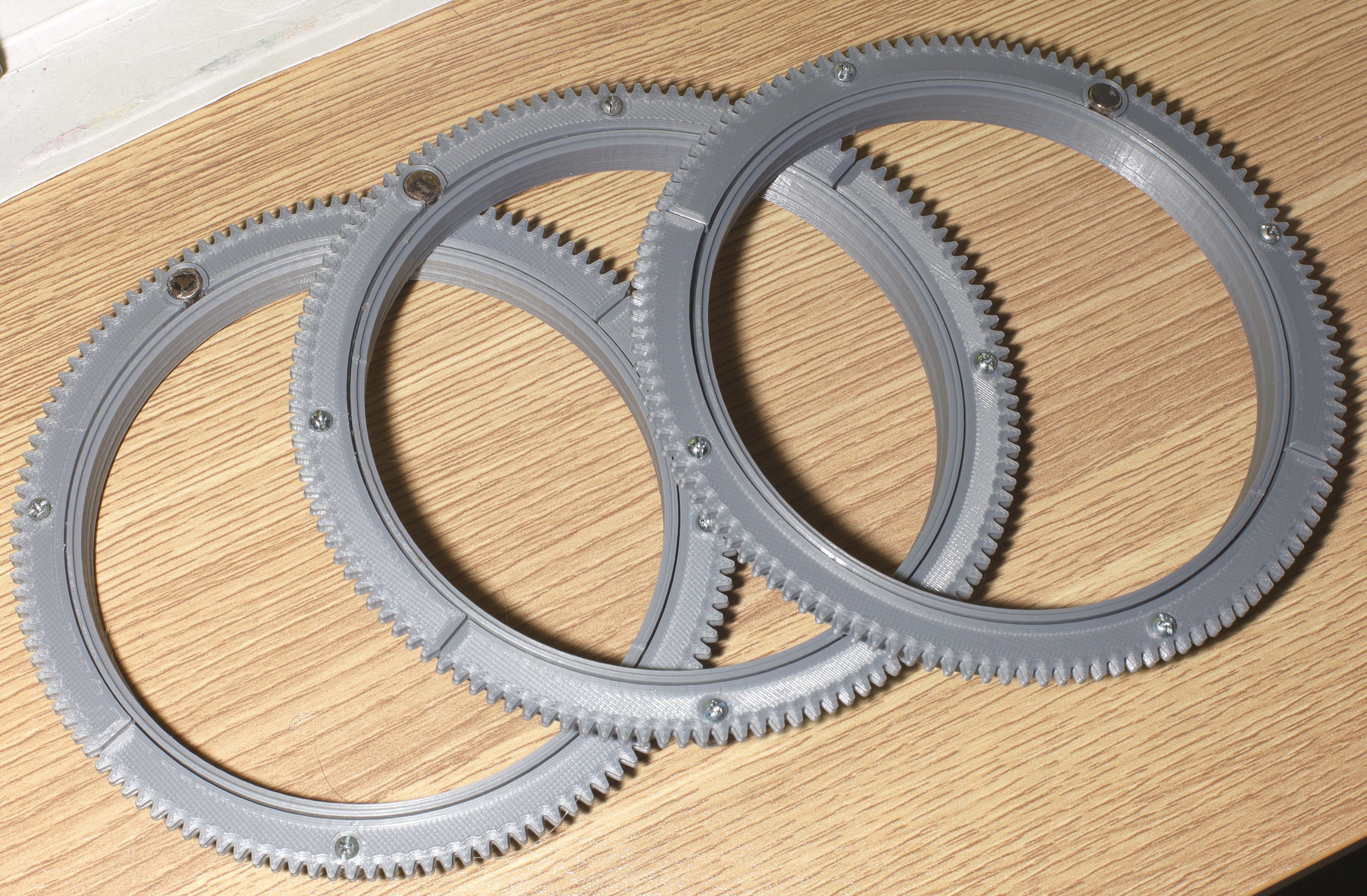
2 years later, an old friend returned. The mane bearing was the 1st 3D printed part a lion ever modeled. It received several upgrades. It kept the 2-56 farsteners since self tappers didn't seem strong enough.
![]()
![]()
![]()
![]()
The difficult overhang got a modern modeled support.
![]()
This one rotated a lot more freely than 2 years ago.
-
Motor mount concepts
10/24/2022 at 05:51 • 0 comments![]()
The mane problem is the motor mount. Ideas converged on a simple rack mount. Plastic designs optimized for efficiency just aren't exciting. They all converge on a grid with walls chopped out to create open spaces. In this case, the circuit boards would be a sandwich under the motor. They're wider than the motor.
-
An update to a mighty nozzle doesn't come easy
10/19/2022 at 01:20 • 0 commentsThere were many attempts to update the motors without paying anything, but the fundamental problems were lowering the speed & increasing the encoder resolution.
The new one is going to require a major expense in motors. The original motors were 75:1 for the lower 2 & 50:1 for the outer one. Even the smallest servos would be real big, heavy, & fragile. A corkscrew drive would be big. Servos wouldn't have better encoders. The whole thing was built around the mighty N-20.
There was a simulation of 300:1 motors which showed promise. It's believed it can never go too slow. The 75:1 motors had problems holding their position in certain orientations. It's not known how fast the motors can stop. The motion would be more precise because the encoders are higher resolution.
The motors are attached via a common platform so they could be upgraded without printing a new nozzle. But with the new encoders, the platforms need to go closer to the gears.
The total shopping list ends up being new motors, new H bridges, & a kg of PLA for $75 or a lot of money for an air vent.
 lion mclionhead

