-
1Remove the heatsinks
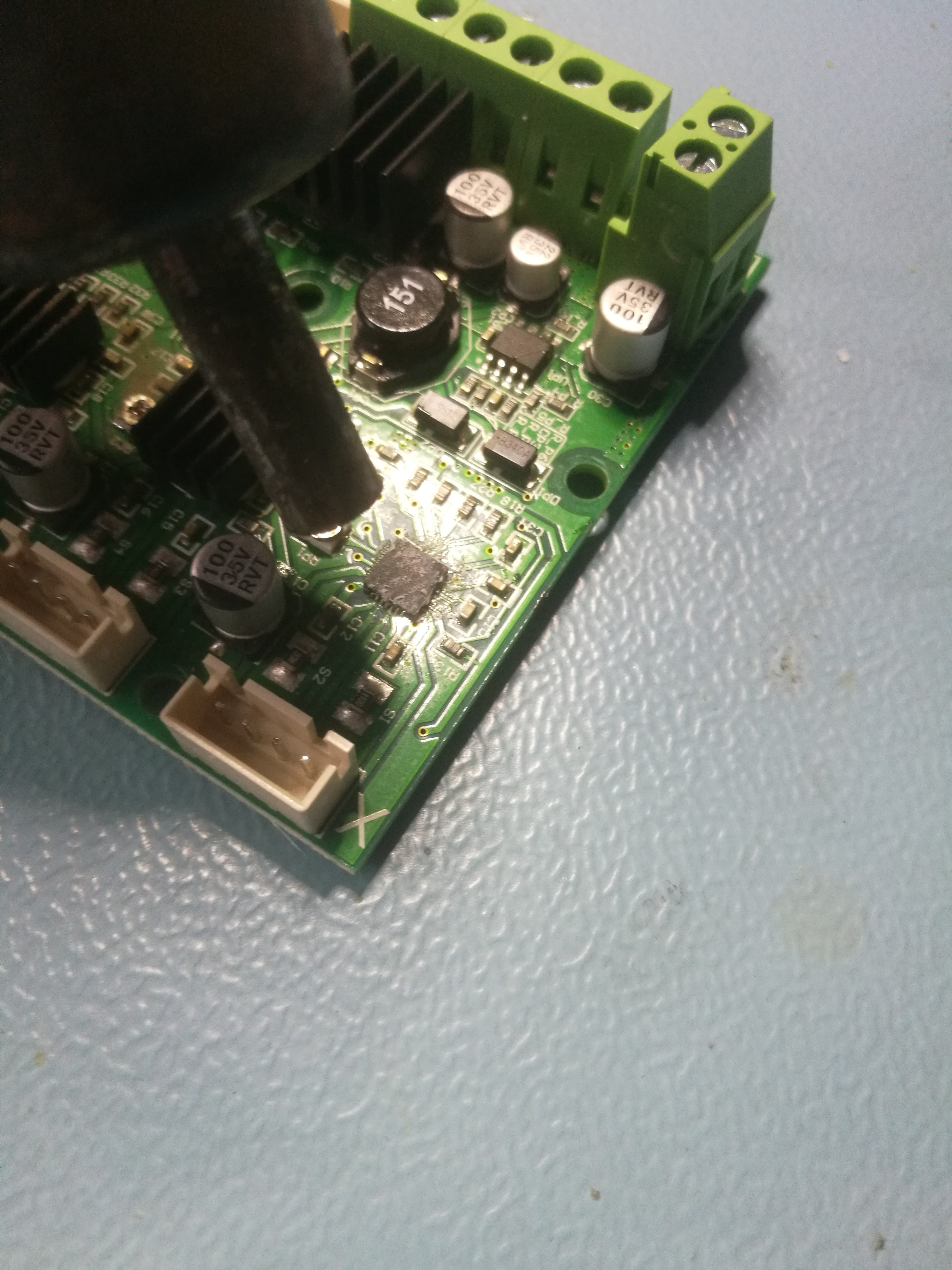
First, you have to remove the heatsinks of the motor controllers. For this, you should warm up the heatsinks with a hot air station. You should avoid overheating the board, rise the temperature gradually until you feel the glue soften. Before soldering out the old motor controller IC you should clean the chips and the heatsink in order to free them from the glue residue. For this, use the hot air station and some isopropyl alcohol. If you want to speed up the cleaning process you may use a scraper made of plastic or wood. But you should never use metal tools for this purpose because you can easily cause permanent damage to your board. During this step always make sure not to heat up other areas of the board, because the connectors, potentiometers, and electrolytic capacitors are sensitive to high temperatures.
![]()
-
2Prepare the chips to remove (optional but useful)
After you removed the heatsinks and the surfaces are clear, the old motor controllers can be removed. Nowadays manufacturers use lead-free solder in their factories. This makes the repair and modification jobs harder. The lead-free solder has a higher melting temperature (217°C) and is generally harder to handle compared to leaded solder. In order to make our situation better, it is recommended to touch up the accessible solder joints with a fine-tip soldering iron and a little leaded solder. This way we can use lower temperatures during disassembly, which radically lowers the chance of damaging other components on the PCB.
In this case, you can access the chip's pins from its side. In order to touch up the chip's thermal pad, I flipped the board and melted some solder on its thermal sinking plane. The solder can travel up to the chip through vias in the thermal plane thanks to capillary action.
-
3Remove the chips
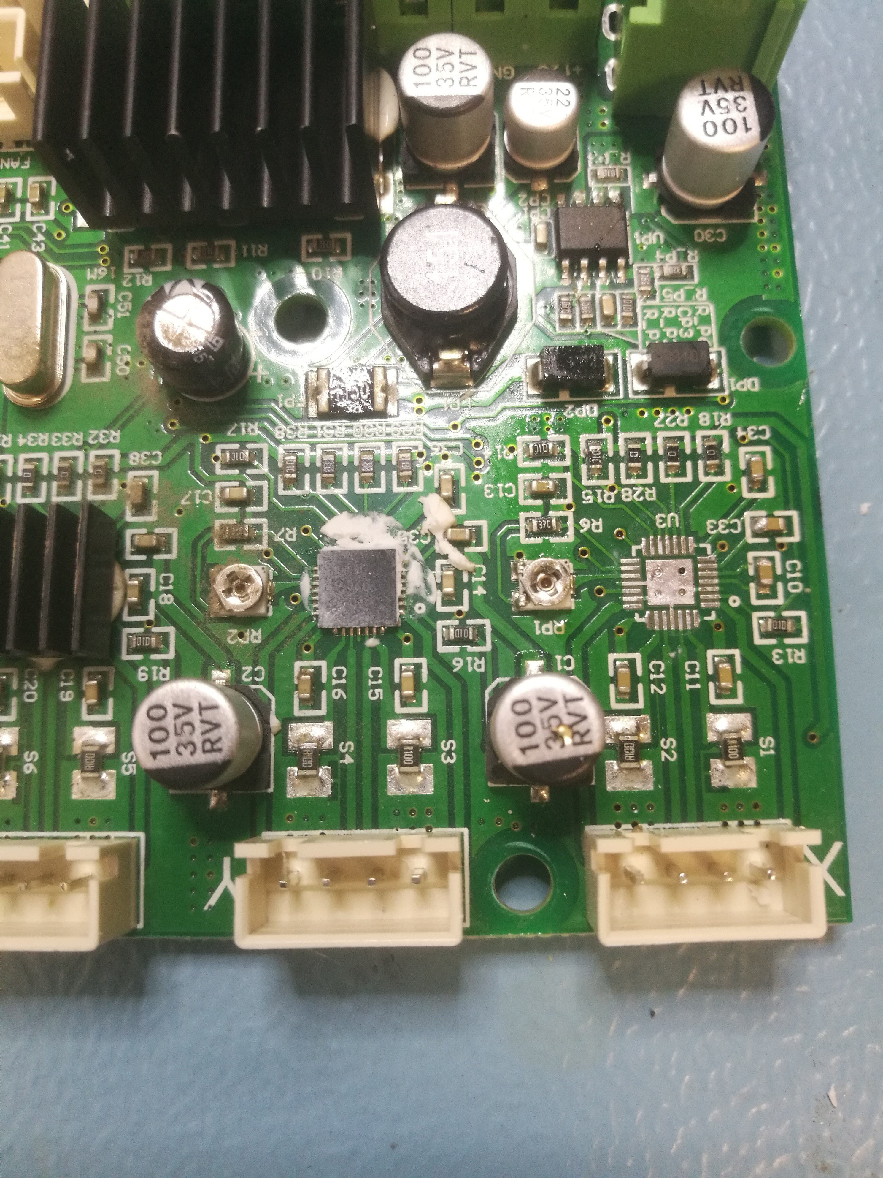
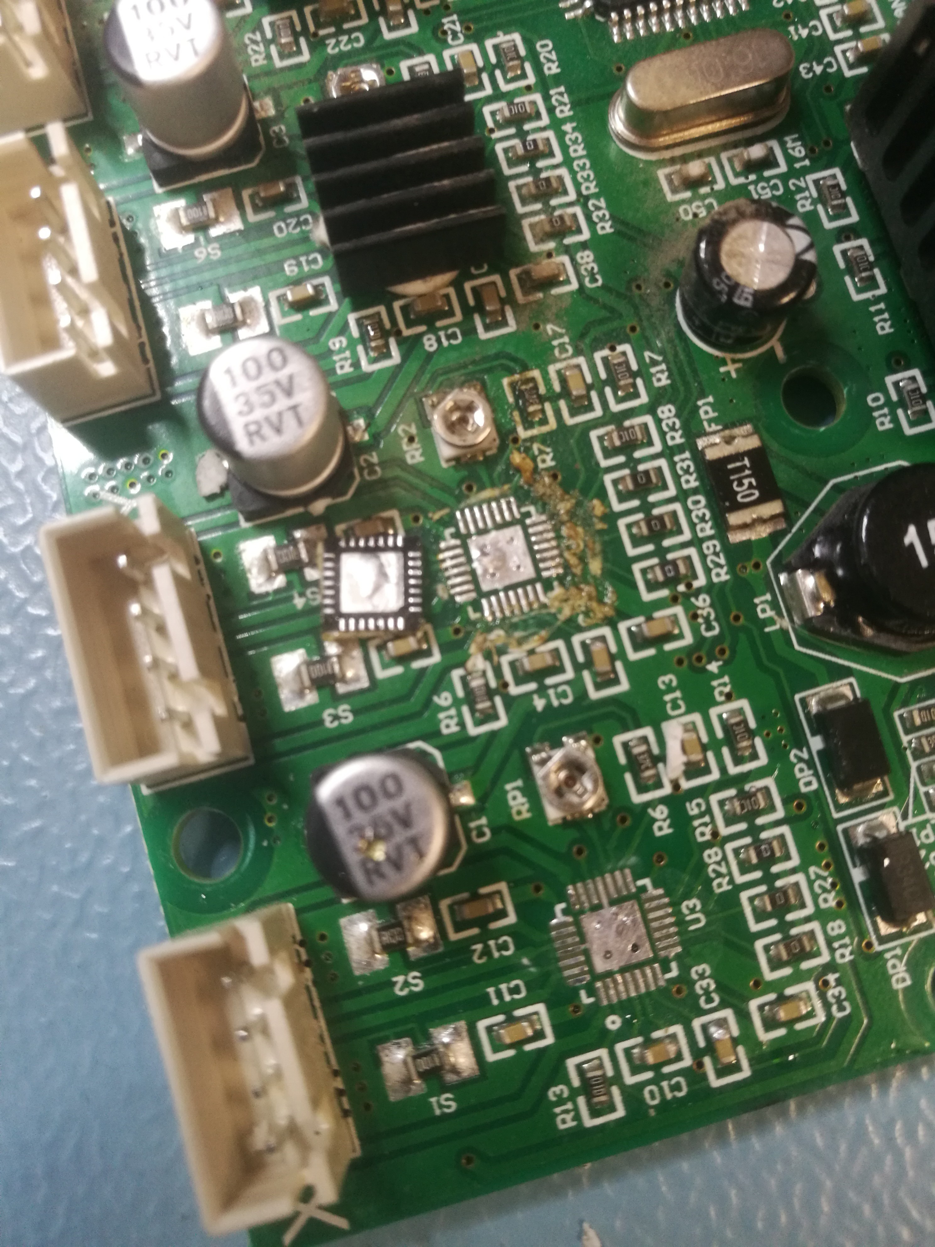
For this step, you should use your hot air station. If you did the previous trick, you should set your station to apx. 200°C, otherwise you should rise the temperature by 20°C. During heating, it is recommended to move your nozzle around, don't fix the hot air stream at a single spot to avoid burning your PCB. When the solder joints are melted you can lift the IC with tweezers. You can help the process by adding flux to the PCB. This helps to spread the heat evenly around the chip, but please do not breathe in the vapors.
![]()
![]()
-
4Prepare the board for the TMC2208s
Before mounting the new components it is crucial to prepare the soldering surfaces in order to achieve reliable and long lasting connections.
After removing the chips, you should touch up the pads with fresh solder and flux. During this, remove the excess solder from the pads and clean the board with IPA. Finally apply a small amount of fresh flux to the pads.
-
5Solder the TMC2208s
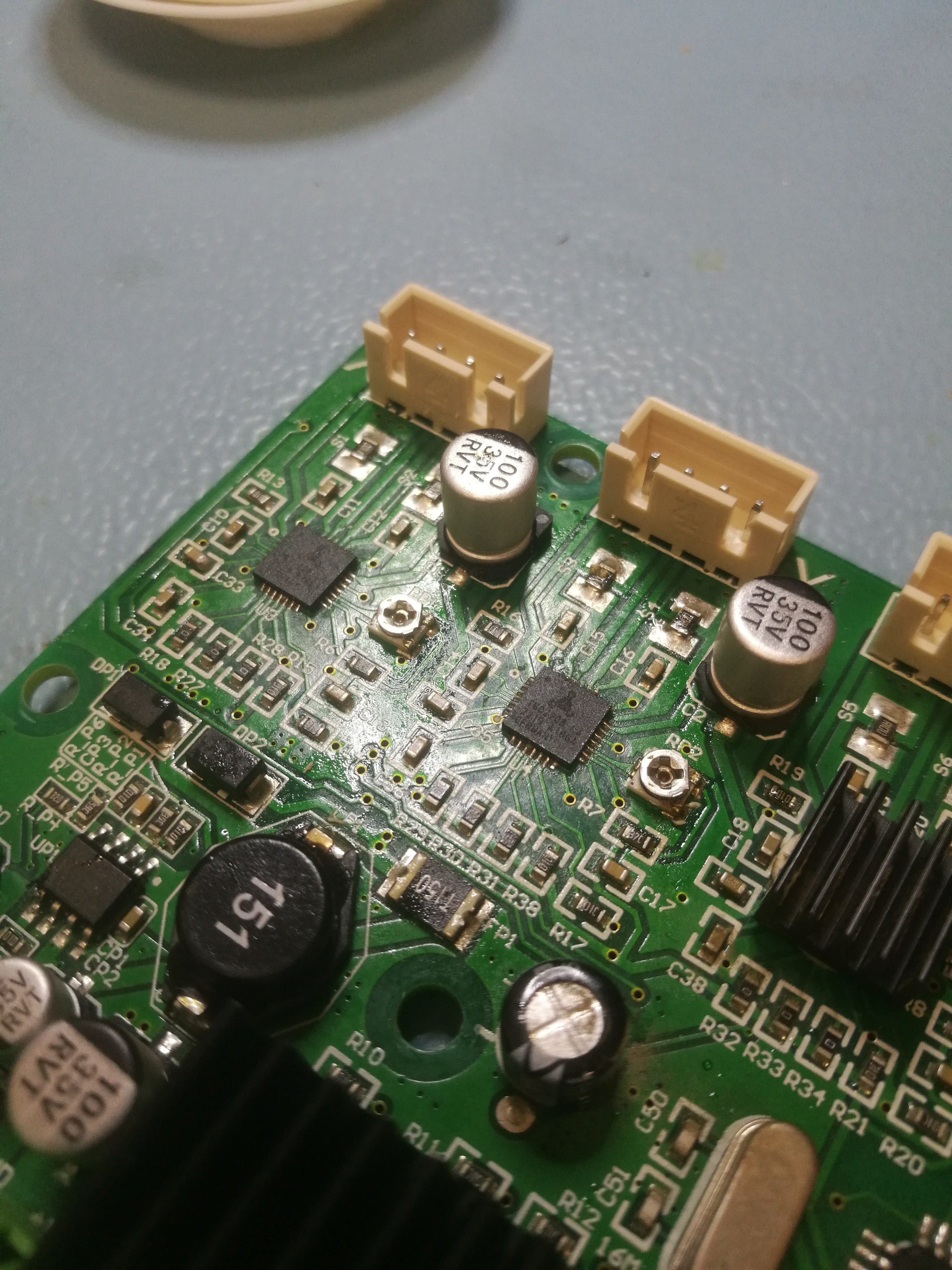
Find the right orientation of the TMC2208 and the board (white circles) and put the chip precisely on the footprint using your tweezers. When you are satisfied with the placement, heat up the device with the hot air station (leaded solder @ 200°C). The soldering is perfect if the chip is "floating" on the pads and the surface tension pulls the device into position. At this point, you should push down the IC to your PCB (while maintaining the proper orientation), remove the heat and wait a couple of seconds to solidify the solder joints.
Don't worry if some solder bubbles out, with a fine tip soldering you can easily remove the excess.
If you are satisfied with the soldering joints, clean the PCB with IPA.
Congratulations! The hardest part is over.
![]()
-
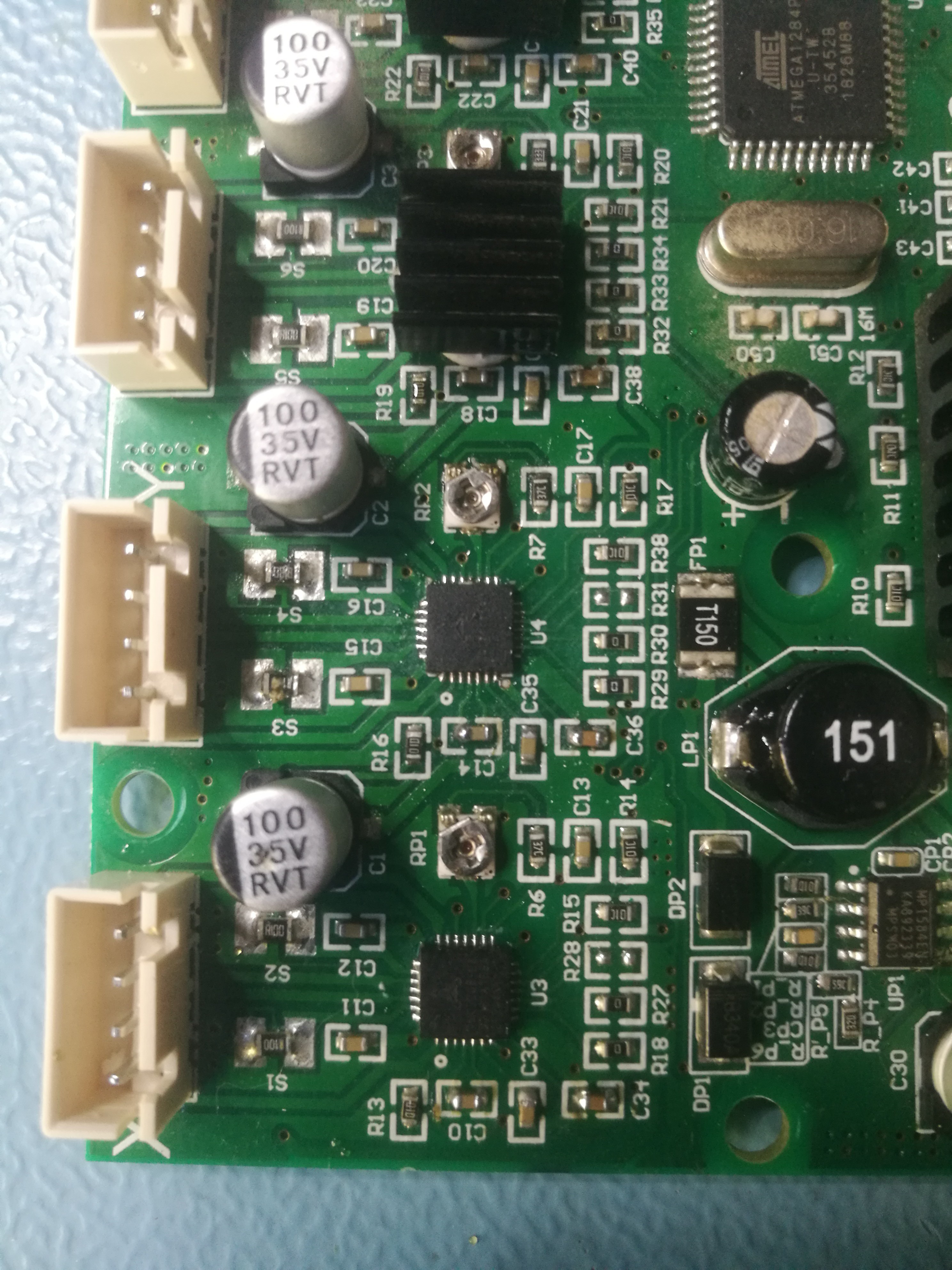
6Remove and change components
In this project, I upgraded only the X and Y axis. So we have to remove the following components:
- R28, R31
- C10, C14
- C34, C36
To remove these devices, you should apply some fresh leaded solder to the pins, after that, use the hot air station to remove them. Before any further steps, you should remove the excess solder and clean the pads with IPA.
Populate 0603 22nF capacitors into positions C10 and C14, and 0603 2.2uF capacitors into positions C34 and C36. The process is the same as it was in the case of the TMCs.
![]()
-
7Heatsinks and the first test
Most of the heat generated by the motor controllers is dissipated by the heat-spreading surfaces under the ICs. However, it is a good approach to mount the original heatsinks to the TMCs as well. Since the package of the device is made of plastic, the heat conductivity, hence the heat dissipation is limited. Because of this, it is favorable to use heat-conducting glue for this purpose, but first of all, make sure that the heatsinks are held in place firmly. Otherwise, the heatsinks can cause shorts on your board.
If you feel ready for testing, connect the printer's power supply to the screw terminals. Before switching the power supply on, do a final check if the connected power lines' polarity is appropriate. If you don't want to properly mount the board in place with the screws, place a non-conductive covering (a piece of paper or plastic) under your board to avoid shorts.
If you did your job right, you shouldn't see any smoke only the blue LED light.
Before the motor-current setup, check the voltages across the board. You should measure on your main input lines around 24V, and apx. 5V on the Atmega controller's filtering capacitors. If something seems fishy, turn off your power supply and check your board in the area, where modifications were made.
-
8Motor current setup #1
The final task is to set up the proper motor current. In this step, we should find the perfect balance. If we apply too much coil current, the system's heat dissipation will increase and after a certain point, we risk the possibility of burning our motor. If we apply too little current, the motor's torque will drop, the chance of layer shifting or other anomalies will increase.
The motor current is set by the potentiometer connected to the motor controller's Vref pin. In theory, based on the datasheet of the TMC2208 you can calculate the proper Vref voltage for your motors. For this you need the following parameters:
- Current sensing resistor on the PCB (Rsense): 0.1R = 100mOhm
- Original nominal motor current (Irms), X, Y, Z: 0.8A
- Original nominal motor current (Irms), E: 1A
Use the following formula for your calculations:
-
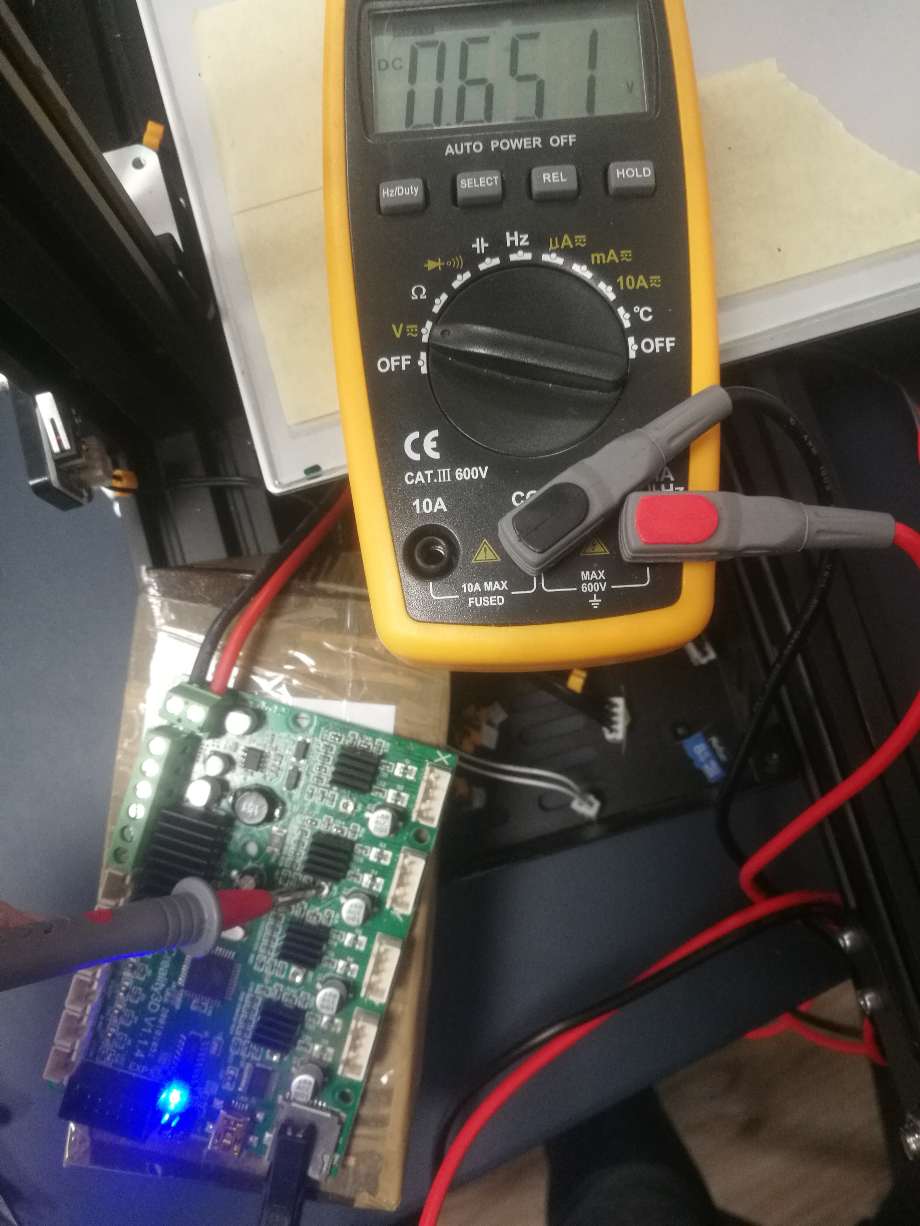
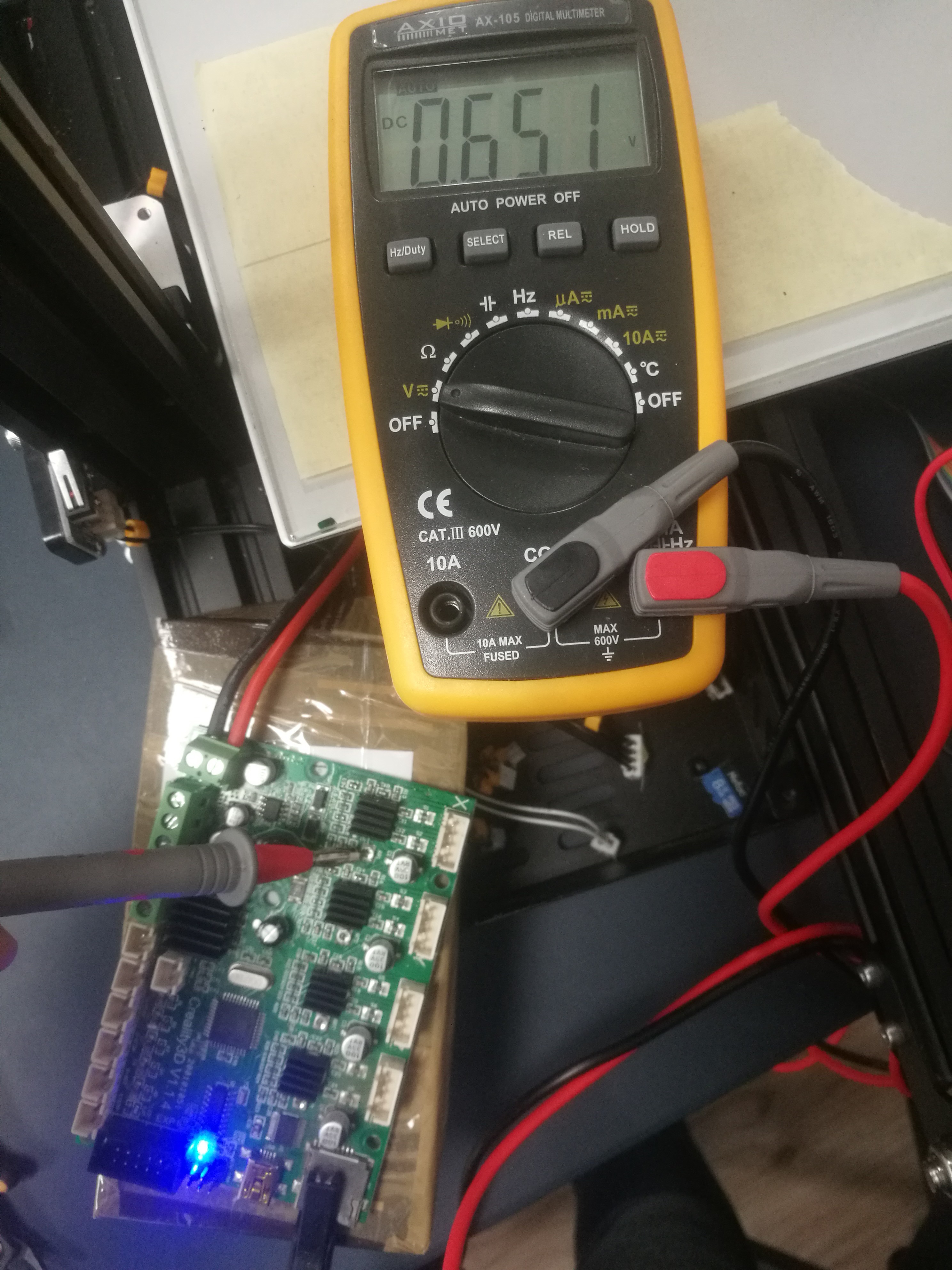
9Motor current setup #2
Before you modify your factory values, always measure them and take notes. This way you can keep the possibility of reverting the changes. This can be done by connecting your multimeter's black (negative) probe to the ground and the red one (positive) to the potentiometer's middle metal part (slider). During the measurement, the board should be in a powered state. Please during this step always isolate your board's bottom surface by placing it in its original place, or use a non-conductive temporary pad.
After measuring the original settings, you should set your new calculated value. For this use a little screwdriver and adjust the potentiometer in multiple small steps. After each step check your new Vref value with the method discussed above.
In my case, the ideal setting was around 0.65V. This setting helps to keep my motors cool meanwhile, I haven't noticed any skipping or artifacts during printing yet. This value may not be ideal for your machine, so I recommend some testing to finetune your setup. Please be very careful with your settings, keep your Vref value between 0.5V and 1V. Voltage under 0.5V is not supported by the motor controller, 1V or greater Vref voltage can cause overloading of your motors.
![]()
![]()
-
10Assemble your machine and enjoy the silence
After the proper setup, you should begin to assemble your machine. Before assembling your machine, switch it off and or disconnect your power cable. After that reconnect your connectors to their original sockets, organize the cabling and fix your board using its original screws. Before testing, it is a good idea to assemble the top cover using only 1 screw. This way you can easily remove it and make it possible to adjust your motor current potentiometers in case of overheating or step skipping.
If everything has gone properly, your printer should work almost noiselessly.
Make your stock Ender 3 printer silent!
Make your stock Ender 3 printer silent, for only a couple of bucks!
Discussions
Become a Hackaday.io Member
Create an account to leave a comment. Already have an account? Log In.