-
1Badge Basics
Imagine it's the summer of 1975. A warm breeze blows through the window as you carefully slide the cover over the Altair 8800 you just finished building. You look down upon the rows of LEDs and switches, and realize with a sense of pride that you're likely the only person in your town that owns their own computer. You're truly living in the future, like Captain Kirk himself.
There's only one question now...what the hell do you do with it?
Just like those brave souls who sent away for their own Altair kit after seeing it in Popular Electronics, you're probably wondering just how you'll put your new high-tech toy to use right about now.
Don't worry, it's perfectly natural to be a bit confused. After all, it doesn't look much like any computer most of us have used in our lifetime. But make no mistake, it is a computer, and once you've learned how to use it, you'll be amazed at what it's capable of.
Speaking the Language
While we've gone through considerable trouble to develop an assembler and emulator that will let you write and test code for the Supercon.6 badge using your modern computer, we believe there's a great benefit to entering a few programs directly on the badge itself using nothing but the buttons on the front panel.
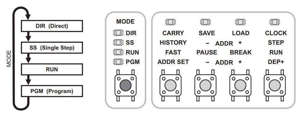
To begin, turn the badge on by pressing the power button on the back. Then press the Mode button on the bottom left until the LED next to PGM lights up.
![]()
This puts the badge into programming mode, where you'll enter instructions directly by using the three sets of four buttons, labeled OPCODE, OPERAND X, and OPERAND Y. To the extreme right you'll see a button labeled "Data In", and if it isn't already, you'll want to press that until the LED next to BIN lights up. This will allow you to use the buttons to directly toggle binary bits, with each lit LED counting as a 1, and each dark LED a 0.
For example, to enter in the binary sequence 0010 0100 1100, the LEDs should look like so:
![]()
To actually enter the 12 bit instruction into the badge, you would press the button labeled DEP+. This will clear the LEDs over the rest of the buttons, resetting them for the next instruction. The - ADDR + buttons can be used to step through the code line-by-line, allowing you to verify and correct any previous entries.
Additional Modes
For the purposes of this document we're largely concerned with the PGM (Programming) mode, but before we move on, a few words should be said about the badge's more advanced functions.
DIR (Direct)
In Direct mode, you're able to save and load programs from both the badge's internal flash and another device over a serial connection. It also allows you to experiment with various parts of the CPU, such as the Accumulator, X and Y Registers, Adder/Subtractor, Logic Group, and Flags. In this mode, instructions can be executed using the Clock button.
For more information on DIR mode, consult pages 18 - 22 of the manual.
SS (Single Step)
In Single Step mode, you can execute an entered program one instruction at a time. This is invaluable for debugging, as the LEDs on the badge will allow you see exactly what's happening inside of the CPU and in RAM. If your program isn't working as you expected, going through it in Single Step mode will likely help you figure out why.
For more information on SS mode, consult pages 23 - 25 of the manual.
One Small Step
Now that we have the basics out of the way, let's now enter a complete instruction into the badge and execute it.
With the badge in PGM mode, we'll first clear any existing instructions by holding ALT and pressing both ADDR buttons together. Now, making sure the "Data In" selector on the bottom right of the badge is set to BIN, configure the LEDs as follows:
![]()
This corresponds to the following instruction, which will place the number 7 into the register R9:
![]()
After confirming the correct LEDs are lit, press the DEP+ button to deposit this instruction. Note that the LEDs over the buttons should turn off in preparation for the next instruction. Instead, press the MODE button until the LED next to RUN lights up, and then press the button labeled RUN. If you've done everything correctly, the LEDs on the badge should appear as they do in the image on the right.
![]()
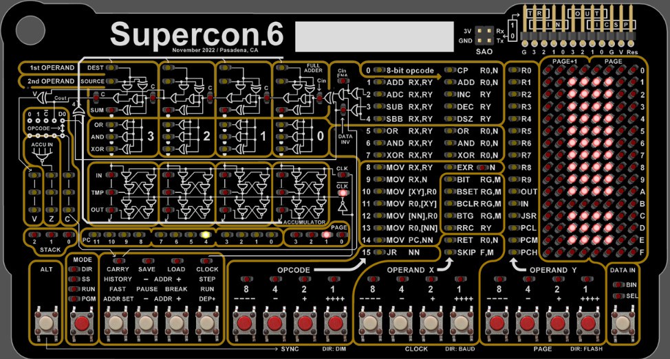
There's actually a lot of information packed into these handful of LEDs, but for now, the important thing to note is that there are three red LEDs lit up on the right side of the LED matrix, next to the number 9. This indicates that, as per the instruction we entered, the number 7 (0111) has been stored in register 9.
Congratulations, you've officially run your first instruction on the 4-bit Supercon.6 badge! Feel free to take a break, and perhaps show off your accomplishment. When you're ready, move on to the next lesson, and let's see if we can do something a little more interesting.
-
2Mathematic Operations
If you've made it this far, we'll assume you understand the basics of entering binary instructions into the Supercon.6 badge and executing them. Now, we're going to ramp things up a bit by chaining multiple instructions together into actual programs.
At the same time, we're going to start introducing new instructions which will aid you on your journey. There's a total of 31 opcodes, and while this basic introduction won't cover all of them, you should know just enough to be dangerous by the time we hit the end.
For now, let's start off with doing some basic math.
Registers
Before we get to the hot digit-on-digit action, we need to talk about something pretty important: registers.
![]()
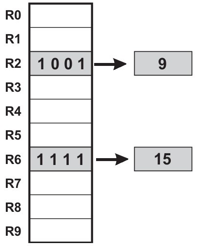
In modern parlance, you might think of these as variables. But it's more accurate to say that they are locations in memory where data can quickly be stored and recalled by the CPU. The 4-bit CPU in the Supercon.6 has 10 General Purpose Registers (R0 through R9), and a whole bunch of interesting Special Purpose registers that we won't get into right now. (Don't worry, there's a whole manual just for them.)
Most instructions will take at least one register as an argument, and some are actually hard-coded to only work with R0. That means to get anything done, you'll need to get comfortable with swapping data between registers.
With that out of the way, let's see how we can use registers to actually get things done on the badge.
Addition
Beyond a literal one-liner, the following is one of the simplest programs possible: we're going to add two numbers together, and view the result. The code for that looks like this:
1001 0000 0010        mov r0, 2       ; Put 2 into R0
1001 0001 0010        mov r1, 2       ; Put 2 into R1
0001 0000 0001        add r0, r1      ; Add the two registers
On the left, we have the binary sequences that you can enter directly into your badge (go ahead, give it a shot), the center has the equivalent code in assembly, and finally to the right we have some descriptive comments.
After running this program, the badge's matrix should look like image on the right. The four LEDs on each row correspond to the 4 bits held in each register, so the binary sequence in row 0 (0100) means the number 4 is currently in R0. The second row of LEDs (0010) show us that 2 is in R1.
![]()
Logically you might have expected the answer to our little addition program would have popped up on a third row, but the add instruction only takes two registers, so that's all we've got to work with. Generally speaking, the result of any operation is going to be held in the first of the two registers, so in this case, we're left with a 4 in R0 and a 2 still lingering in R1.
Now, the astute reader may have noticed that in this program (much like in the single instruction demonstration from the previous lesson) we didn't give any command to actually output our result to the LED matrix. That's because the matrix isn't actually a display in the traditional sense -- it's a window into the working memory of the badge's CPU.
The matrix can be used as a display by carefully manipulating the memory within its purview, which is something we'll get to later. For now, we'll just be directly viewing the contents of the registers.
Subtraction
As you might expect, subtraction looks a lot like addition:
1001 0000 1100        mov r0, 12      ; Put 12 into R0
1001 0001 0111        mov r1, 7       ; Put 7 into R1
0011 0000 0001        sub r0, r1      ; Subtract R1 from R0
Running the program on your badge, we see that the LEDs next to R1 (0111) once again show that it's left with its original value of 7, while the LEDs for R0 (0101) show the result of 12 minus 7 to be 5.
Increment/Decrement
As you start to write more complex programs, you'll often find the need to add or subtract 1 from a register -- such as when you want to keep track of how many times a loop has gone around. In fact, it's such a common task that the CPU has dedicated inc (increment) and dec (decrement) instructions for it.
Consider the following program:
1001 0000 0010        mov r0, 2     ; Put 1 into R0
1000 0001 0000        mov r1, r0    ; Copy R0 to R1
0000 0010 0000        inc r0        ; Add 1 to R0
0000 0010 0000        inc r0        ; Add 1 to R0
0000 0011 0001        dec r1        ; Sub 1 from R1
First we place 2 into R0, and then in the next line copy that over to R1, making them equal. We then run inc on R0 twice, and dec on R1.
![]()
When you run the program and look at the LEDs, you'll see that R0 now contains the result of 2 + 1 + 1, or 4 (0100). R1 on the other hand is down to 1 (0001), since we subtracted 1 from the original 2.
Technically you could accomplish the same thing with the add and sub instructions, but in those cases, you'd need to provide a second register that contained 1. On such a constrained system, that's a big ask, which is why the inc and dec instructions are so valuable.
Multiplication
On the other side of the spectrum, multiplication is something you'll do relatively infrequently. In fact, there isn't even a multiply instruction. Of course, that doesn't mean we can't do it -- we've just got to think outside the box a bit.
For example, you might not have a command that will let you perform 5 x 3, but you can add 5 to itself repeatedly:
1001 0000 0101        mov r0, 5       ; Put 5 into R0
1000 0001 0000        mov r1, r0      ; Copy R0 to R1
0001 0000 0001        add r0, r1      ; Add (5 + 5)
0001 0000 0001        add r0, r1      ; Add again (5 + 5 + 5)
The result (15) will light up all four LEDs on R0, which incidentally makes it the largest number we can actually handle with these 4-bit instructions. There are technically some instructions that take 8-bit numbers, which we'll get to shortly.
Division
Division can be done in much the same way, you just keeping subtracting the number until you hit zero. Of course, the trick there is keeping track of how many times you've subtracted the number, and checking if the result is zero or not.
Neither of these things are concepts we've covered yet, which makes this a logical place to introduce a new topic: Program Flow
-
3Program Flow
So far, all of our programs have been only a few lines that just ran straight through. But as you develop more complex code, you'll eventually want to perform loops, or change the behavior of the program depending on the value stored in a particular register.
While these are core programming concepts, the way they are accomplished on such a constrained system as the Supercon.6 badge might not be as intuitive as you're used to. For example, you won't find the traditional IF...THEN statements among the CPU's opcodes, but there are some equivalent instructions that you'll end up using a lot as you move forward.
Compare and Skip
The cp (compare) instruction does exactly what it sounds like: compares two values. But there's a bit of a trick, as this is one of those instructions that can only be used with register 0. So any time you want to compare one value to another, you'll always have to stuff it into R0 first.
Using the cp instruction, you'll be able to determine if the given value is the same, less than, or more than what's stored in R0. This is done by checking the status of the C and Z flags after making the comparison.
There's a few things you can do with these flags, but perhaps the most common instruction you'll use in conjunction with them is skip, which as you might have guessed, conditionally skips lines in the program based on the status of the flags.
Let's demonstrate with a small program:
1001 0000 1111        mov r0, 15      ; Put 15 into R0
0000 0000 0101        cp r0, 5        ; Compare R0 to 5
0000 1111 0001        skip c, 1       ; Skip next line if R0 < 5
1001 0000 0010        mov r0, 2       ; Put 2 into R0
0000 0000 1111        cp r0, 15       ; Compare R0 to 15
0000 1111 1010        skip z, 2       ; Skip next two lines if R0 = 15
1001 0000 0000        mov r0, 0       ; Put 0 into R0
1001 0001 1111        mov r1, 15      ; Put 15 into R1
After running this program, you should see four LEDs on the right side of row 0, indicating that R0 still contains the original value of 15. That's because the two lines which would have changed it were skipped, first because the value in R0 was higher than 5, and again because it was equal to 15.
![]()
Additionally, you should see that there are no LEDs lit on row 1. That's because the second skip instruction actually skipped two lines, not one. The ability to skip multiple instructions is definitely helpful, but keep in mind that you can only jump over a maximum of 4 lines.
Skipping a line after a comparison might seem backwards to modern programmers -- normally the lines following an IF statement are the ones you expect to execute. But as you'll see, skipping instructions can be just as useful as executing them.
Relative Jumps (Looping)
While there isn't exactly a loop instruction, the 4-bit CPU is able to jump forward and backwards through the program at will, which if carefully utilized, allows you to repeat a given section of your code (or avoid it entirely).
The following combines the jr (jump relative) instruction with inc, cp, and skip to demonstrate how the flow of a program can be controlled:
1001 0000 0001        mov r0, 1       ; Put 1 into R0
0000 0010 0000        inc r0          ; Increment R0
0000 0000 0101        cp r0, 5        ; Compare R0 to 5
0000 1111 1001        skip z, 1       ; Skip next line if R0 = 5
1111 1111 1100        jr -4           ; Jump back 4 lines
1001 0001 1111        mov r1, 15      ; Put 15 into R1
There's a bit going on here, so let's walk through it step-by-step.
![]()
First we place a 1 in R0, and then increment it. At this point, R0 equals 2. We compare it to 5, find that it's not equal, so we do not skip the jr -4 instruction. This makes the program go back 4 lines (the jr instruction itself counts as one line) to inc r0. We now have a loop that will continue until R0 equals 5.
Once that happens, the loop exits, and our final instruction can execute. The resulting LEDs should look like the image on the right -- with 5 in R0 and 15 in R1.
Decrement and Skip
As mentioned previously, the inc and dec instructions are very handy, especially when combined with jr and skip so much so that there's actually a ready-made combo instruction you can use that makes things a little easier: dsz
This instruction will decrement a given register until it equals zero, and when it does, skips the next instruction. Here's a brief example:
1001 0000 0101        mov r0, 5       ; Put 5 into R0
1001 0001 1010        mov r1, 10      ; Put 10 into R1
0000 0010 0001        inc r1          ; Increment R1
0000 0100 0000        dsz r0          ; Decrement R0 until 0
1111 1111 1101        jr -3           ; Jump back 3 lines
1001 0010 1111        mov r2, 15      ; Put 15 into R2
![]()
In this example, we increment R1 while we decrement R0, with a jr instruction to continue looping around until dsz sees that R0 equals 0 and skips it. The end result, as shown on the right, should be no LEDs lit on row 0, and four each in rows 1 and 2.
As you can see, this instruction is perfect for when you want to repeat an action a specific number of times. It saves you a couple lines of code compared to doing it manually, plus you don't have to remember which flags mean what since it's hard-coded to look for the equal condition.
Division (Revisited)
Now that we've covered loops and conditional control of the program flow, let's tackle the division program mentioned in the previous chapter:
1001 0000 1111        mov r0, 15      ; Put 15 into R0
1001 0001 0011        mov r1, 3       ; Put 3 into R1
1001 0010 0001        mov r2, 1       ; Start result counter at 1

0011 0000 0001        sub r0, r1      ; Subtract R1 from R0
0000 1111 1010        skip z, 2       ; Skip next two lines if result is zero
0000 0010 0010        inc r2          ; Increment counter
1111 1111 1100        jr -4           ; Jump back to division
First the dividend (15) goes into R0, and the divisor (3) is held in R1. The program then uses a loop to keep subtracting R1 from R0 until the result is 0. We don't need to use cp here, as the sub instruction will handily raise the Z flag for us. Once R0 is empty, the next two lines are skipped so that the loop can exit.
![]()
The final result should look like the image on the right -- row 0 will show no LEDs, row 1 will have 0011 (3), and row 2 will display the answer to our division problem: 5 (0101).
But wait a minute...what happens if there's a remainder? Or you want to divide a small number by a larger one? Well, that's a good question, you should look into it and find out. After all, we can't show you everything here.
That wraps up the Program Flow chapter. Next up, Hardware I/O.
-
4Hardware I/O
As you've come to realize, compared to a modern computer, the Supercon.6 badge only offers the barest of necessities. But it does include some interesting onboard capabilities, and there's a whole host of system parameters that can be controlled from software. There's also a physical expansion port that features four input and four output pins, which can be used to connect the badge to other devices.
To truly see what the badge is capable of, you should consult the full documentation. Especially in regards to the Special Function Registers (SFRs) which allow you to modify the badge's configuration -- the topic actually has its own dedicated manual.
But to give you an idea of what's possible, let's take a look at some examples.
Setting CPU Speed
![]()
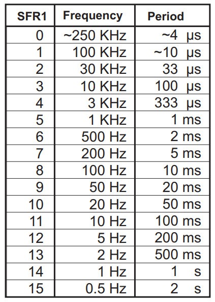
If you've looked at the example programs for the badge, you'll know many of them start off with an instruction that sets the speed of the emulated 4-bit CPU. While the host PIC24FJ256 always runs at 16 MHz, the emulated CPU has 16 speed levels you can chose from.
There's no special instruction to set the CPU speed -- instead, you simply use mov to write the desired setting to the Special Function Register 0xF0 in much the same way you would the General Purpose Registers R0 through R9. The same is generally true among the rest of the SFRs, which makes configuring the badge's hardware very straight-forward once you've consulted the documentation and know what the acceptable parameters are.
The following example demonstrates how the CPU's frequency can be changed on the fly, and how it impacts the speed of program execution:
1001 0000 1000        mov r0, 8       ; Put 8 into R0
1100 1111 0001        mov [0xF1], r0  ; Set CPU speed to 8 (100 Hz)

1001 0001 1111        mov r1, 15      ; Put 15 into R1
0000 0100 0001        dsz r1          ; Decrement R1 until 0
1111 1111 1110        jr -2           ; Jump back 2 lines

1001 0000 1100        mov r0, 12      ; Put 10 into R0
1100 1111 0001        mov [0xF1], r0  ; Set CPU speed to 12 (5 Hz)

1001 0001 1111        mov r1, 15      ; Repeat same loop as before
0000 0100 0001        dsz r1
1111 1111 1110        jr -2
In this example, we're using dsz to count from 15 down to zero, first with the CPU frequency set to 100 Hz and then again at 5 Hz. Running this program, you should see the LEDs on row 1 blink rapidly for a little less than a second on the first go around. When the LEDs on row 1 come back and start counting down again, this it will take approximately 8 seconds to complete the loop.
Generating Random Numbers
Given how few luxuries are included in the Supercon.6 badge, you might be surprised to find that it has an onboard system for generating high-quality (relatively speaking) random numbers.
It's more accurate to say that the badge has what's known as a pseudorandom number generator (PRNG), because despite the clever tricks Voja implemented (you can read about the specific technique used on page 26 of the Special Function Register manual) it's difficult to get truly random data without more specialized hardware. Still, the feature is a pleasant surprise that can definitely be handy for many programs.
To get yourself four bits of fresh randomness, you simply need to use mov to read from the Special Function Register 0xFF:
1001 0000 1100        mov r0, 12        ; Set CPU speed to 12 (5 Hz)
1100 1111 0001        mov [0xF1], r0    ;

1001 0001 1111        mov r1, 15        ; Put 15 into R1
1101 1111 1111        mov r0, [0xFF]    ; Read from PRNG, put into R0
0000 0100 0001        dsz r1            ; Decrement R1 until 0
1111 1111 1101        jr -3             ; Jump back 3 lines
Running this program, you should see the LEDs on row 0 jumping between random values for several seconds, while the LEDs on row 1 count down from 15. Note that we only reduced the CPU speed to slow the process down and make it easier to visualize -- adjusting the CPU frequency is not necessary to read from the PRNG.
Getting Button Status
To this point, all of our programs have run on their own with no user input. But should you actually want to hear from the user from time to time, there's a Special Function Register you can read to see which button on the face of the badge has been pressed.
Finding the last button pressed is as easy as doing a single mov instruction to SFR 0xFD:
1101 1111 1101 mov r0, [0xFD] ; Read last button pressed into R0
Run this one-line program, and you should notice that the LEDs in row 0 change each time you press a button on the front of the badge. You could experiment to figure out the value of each button, but thankfully that data has already been provided for us in the manual:
![]()
If you just want to know when a button has been pressed, but aren't necessarily worried about which one, there's a SFR for that as well: 0xFC
The trick with this one though is that the 4-bit value in 0xFC actually indicates four separate pieces of information, so you need to isolate each bit instead of just comparing the whole value. To do that we can use the aptly-named bit instruction:
1001 0001 0000        mov r1, 0       ; Zero out R1
1101 1111 1100        mov R0, [0xFC]  ; Read key status into R0
0000 1001 0010        bit R0, 2       ; If second bit of R0 is 0, set Z flag
0000 1111 1001        skip z, 1       ; Skip next line if Z is set
1001 0001 1111        mov r1, 15      ; Put 15 into R1
This program checks the second bit of SFR 0xFC, which corresponds to the AnyPress flag. Put simply, if that bit is 1, then one of the buttons on the badge is being pressed. The bit command lets us check that specific bit, and skip is being used to jump over the line that loads 15 into R1 should it read a 0.
The end result is that pressing any button (or at least, most) should cause all four LEDs on row 1 to light up.
Using the Expansion Interface
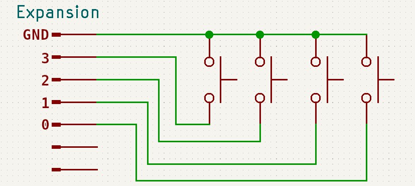
The Supercon.6 badge features a 12-pin expansion connector which is used not only for programming the badge initially, but also offers four input pins and four output pins which can be easily controlled via software.
In fact, getting the status of the input pins is so simple that you don't technically have to do anything to see it in action. Have you noticed that when programs are running on the badge, four LEDs on row B of the matrix always seem to be lit? That's actually the status of the four input pins -- if you short any of those pins to ground, its corresponding light will go out.
Using the bit instruction against the SFR 0x0B will let you pull this information into your programs:
1001 0001 0000        mov r1, 0       ; Zero out R1
1101 0000 1011        mov r0, [0x0B]  ; Read input pin status into R0
0000 1001 0001        bit r0, 1       ; If first bit of R0 is 0, set Z flag
0000 1111 1101        skip nz, 1      ; Skip next line if Z is NOT set
1001 0001 1111        mov r1, 15      ; Put 15 into R1
With this program running, shorting out the input pin 1 on the expansion connector to ground should cause 4 LEDs to light up on row 1. Each bit in 0x0B corresponds to its own pin, so wiring up four additional buttons on your badge is quite straightforward:
![]()
Using the output side of the expansion connector is much the same, except instead of reading from the individual bits of SFR 0x0B, you'll be writing to the bits of 0x0A using either the bset instruction to set them directly or the btg instruction to invert their current state.
Communicating over UART
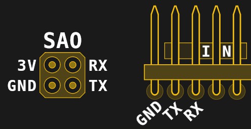
Ask any hardware hacker and they'll tell you the same -- it's not a proper computer unless it has a serial port, and the Supercon.6 badge is no exception. Not only will you use the UART capabilities of the badge to upload and download programs from other badges or your "real" computer, it can also be used for arbitrary communication with all sorts of interesting gadgets.
![]()
Compared to performing many other functions, the process of transmitting and receiving data over UART is actually quite a bit easier than you're probably expecting. If there's a trick, it's that for each byte you send out over the wire, you need to make two separate writes -- the first 4 bits go into SFR 0xF7 and the other 4 into SFR 0xF6. Once the second half of the byte has been written to 0xF6, it will automatically be transmitted.
It's also worth mentioning that, by default, the badge uses the SAO header for UART and not the pins in the expansion header. This behavior can be changed in the configuration, but for the sake of simplicity, we'll leave it at the default for this example.
Note: As of this writing (Nov 4th), a bug in the badge firmware prevents the UART pins in the expansion header from functioning properly. This will be addressed in an update, but in the meantime, the SAO pins do work as expected.
As a basic example, let's look at the following program which will send the ASCII letter "A" out continuously over UART:
1001 0010 0100        mov r2, 0b0100    ; High nibble of ASCII "A"
1001 0011 0001        mov r3, 0b0001    ; Low nibble of ASCII "A"

1000 0000 0010        mov r0, r2        ; Write high nibble to UART
1100 1111 0111        mov [0xF7], r0    ;
1000 0000 0011        mov r0, r3        ; Write low nibble to UART
1100 1111 0110        mov [0xF6], r0    ; Transmit
The operation is simple in principle...but in practice you can see how difficult it would be to send any serious message using just the General Purpose Registers. To make any real use of the UART, you're going to need a more efficient way of shoving around data than we've looked at so far.
Sounds like the perfect time to move onto the next chapter: Manipulating Memory.
-
5Manipulating Memory
So far, we've been mainly concerned with the General Purpose Registers R0 through R9, and a handful of the Special Function Registers (SFRs) that allow us to poke and prod at the inner workings of the badge. For a great many tasks, this is sufficient.
![]()
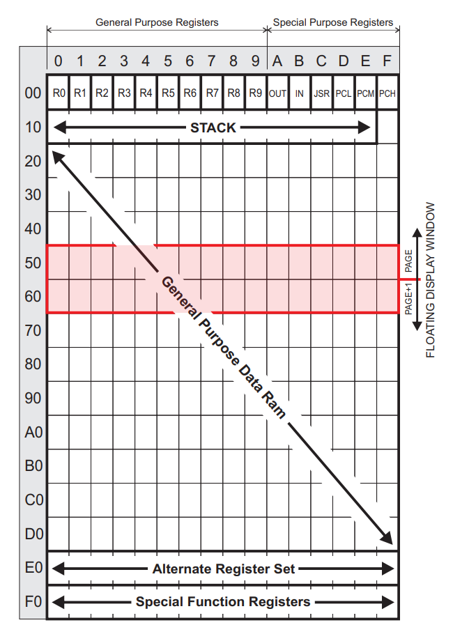
But to get the most out of the badge, you'll need to know a bit more about addressing and handling its memory. If you've got large (relatively speaking) amounts of data you want to stash away and recover later, the General Purpose Registers simply aren't going to cut it. Luckily for us, there's a sizable swath of RAM sandwiched between the common and special registers that we're able to utilize.
As you can see in the image to the right, the memory of the Supercon.6 badge can be thought of as a sort of spreadsheet. We've used friendly names like R0 and R1 to refer to cells in this spreadsheet so far, which the CPU's instructions have been largely designed around for ease of use. But there are variations of the instructions which allow for different ways of addressing those locations.
In the following examples, we're going to look at some of the more advanced ways of utilizing the memory on the Supercon.6 badge, and the capabilities it can unlock.
Direct Memory Addressing
While it's true that some instructions are setup in such a way that they can only be used with a specific register (often R0), it's important to understand that there's nothing inherently unique about the registers we've become accustomed to using in this document. When you see R0 or R1 in a program, what you're essentially looking at is a bookmark that points to a particular location in the badge's memory. It's a handy thing for us humans, but as far the CPU is concerned, memory is memory.
As such, there are special variants of instructions like mov which can be pointed to an arbitrary memory location. While using these takes a bit more effort on the programmer's part, as you need to keep track of where you're stashing your data, it doesn't have much of an impact on the code itself:
1001 0000 1100        mov r0, 12        ; First put value in R0
1100 0001 0011        mov [19], r0      ; Move into memory location

1001 0000 1111        mov r0, 15        ; Put new value into R0
1100 0001 0100        mov [20], r0      ; Copy to sequential locations
1100 0001 0101        mov [21], r0      ; Note different mov opcode
1100 0001 0110        mov [22], r0      ;

1101 0001 0101        mov r0, [21]      ; Read value from memory into R0
You still need to move the value into R0 temporarily when storing or recalling it, but for data that you don't need to access frequently, this is a great way to free up your named registers for higher priority tasks.
Indirect Memory Addressing
Directly addressing memory is handy, but it has its limitations. Specifically, you still have to hard-code the values you want to address. In many cases that's not a huge problem, but it would be more efficient to loop through a read or write operation while simply iterating the memory address.
As it so happens, there's a version of mov which allows us to do exactly that. This instruction takes two registers as its input, representing the high and low nibble of the desired address. This not only enables the expression of 8 bit memory address (0 to 255), but allows you to manipulate the desired address using the instructions we've already learned.
In this context, it helps to think of the registers as the indexes in a two-dimensional array: with the first register representing the desired column, and the second the row. This also happens to be how the LED matrix is arranged...a very convenient relationship, but we'll get to that in a moment.
Let's look at this example, which can quickly fill a block of memory with a desired value:
1001 0000 1111        mov r0, 15       ; First put value in R0

1001 0001 0001        mov r1, 1        ; Page 1 of memory
1001 0010 1110        mov r2, 14       ; Start at row 15 so we can use dsz

1010 0001 0010        mov [r1:r2], r0  ; Provide dimensions to mov
0000 0100 0010        dsz r2           ; Loop to fill 14 addresses
1111 1111 1101        jr -3            ;

1001 0000 0000        mov r0, 0        ; Direct addressing
1100 0001 1011        mov [1:11], r0   ; in two dimensions
After running this program, you should see that around 3/4 of the left side of the LED matrix is fully filled, representing the 10 memory locations in which we deposited the value 15. Not bad for three lines of code. One of the rows will also be empty, which is the result of the last line, which demonstrates directly addressing a memory location in two dimensions.
Of course you should also have noticed that, if it wasn't for the handful of lit LEDs on the right side of the matrix cluttering things up, the display would be showing a perfect exclamation mark...
Which means we're ready to combine everything we've learned so far and tackle the final challenge of our journey: Graphics.
-
6Graphics
As covered previously in this document, and as you've at this point seen for yourself, the LED matrix on the Supercon.6 badge isn't a display in the traditional sense.
![]()
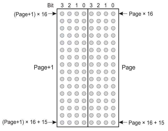
Instead it's a live window into the memory of the computer, which expresses the binary values in each nibble of memory with four LEDs. Paired with the badge's Single Step mode, it offers a phenomenal level of transparency when you're working with your programs, as it lets you see in real-time when each and every bit has been changed.
But even though there's no turn-key method of displaying images or text on the LED matrix, it's not hard to imagine how it could be pressed into service as a general purpose output device. After all, we've now seen how to directly manipulate values in memory, and we know how the LEDs will light in response to those values.
If you combine that with the methods of program flow control like loops, skips, and jumps that we learned earlier, it's possible to "draw" rudimentary images using the 16x8 LED array.
Clearing the Screen (Setting Memory Page)
There's an obvious problem with this idea though, as all of our General Purpose Registers, and even some of the Special Function Registers (SFRs) are already visible on the matrix and taking up space on our "screen" that we can't afford to lose given the extreme low resolution we're working with.
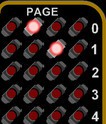
Luckily, there's a simple solution to this problem: SFR 0xF0 allows us to change which area of memory the matrix examines. So with just a single instruction we can point the matrix at a fresh "page" where the only data that appears is what we've intentionally placed there:
1001 0000 0010        mov r0, 2        ; Move matrix over to page 2
1100 1111 0000        mov [0xF0], r0   ;
After running this program, you might think nothing happened. But a close look at the matrix will show that every single LED is turned off; a condition that until this point, you would have never seen while a program was running. That's not because we've disabled it, we've simply pointed it at an unused area of RAM, so there's nothing to show.
Which means the only thing left to do is fill that RAM with something interesting to look at.
Exclamation (Revisited)
Armed with this new knowledge, you could go back to the previous example and draw that exclamation mark with a nice clean background. But it would would still be off-center, because each side of the matrix is only showing one page of RAM.
To fix this, we'll need to store each half of our sprite in a separate register, and then use a loop and indirect memory addressing to draw it out:
1001 0000 0010        mov r0, 2        ; Move to page 2
1100 1111 0000        mov [0xF0], r0

1001 0101 0011        mov r5, 0b0011   ; Left side of icon
1001 0110 1100        mov r6, 0b1100   ; Right side of icon

1001 0010 0010        mov r2, 2        ; Register for page 2
1001 0011 0011        mov r3, 3        ; Register for page 3
1001 0100 1110        mov r4, 14       ; Start at row 14

1000 0000 0101        mov r0, r5       ; Get left side data into R0
1010 0011 0100        mov [r3:r4], r0  ; Draw left side
1000 0000 0110        mov r0, r6       ; Get right side data into R0
1010 0010 0100        mov [r2:r4], r0  ; Draw right side
0000 0100 0100        dsz r4           ; Decrement row
1111 1111 1010        jr -6            ; Draw 14 rows

1001 0000 0000        mov r0, 0        ; Clear line at bottom
1100 0011 1011        mov [3:11], r0   ;
1100 0010 1011        mov [2:11], r0   ;
If the program works correctly, you should have a big exclamation mark in the exact center of your matrix.
![]()
With some imagination, and a careful tally of where all your bits are in memory, this basic technique can be used to write out text or display simplistic images. By reading the status of the badge buttons, they could even be made to move.
We can't wait to see who's the first to create a Snake or Tetris clone for their badge.
Das Blinkenlights
If you've followed along through this whole guide, congratulations. In a relatively short period of time, you've gone from kindergarten-level arithmetic to drawing images by directly manipulating bits in memory; and you've done it all with nothing more exotic than a handful of tactile buttons and a few (hundred) LEDs.
In honor of this accomplishment, the final program combines a little bit of everything covered in the previous lessons to produce a visually impressive "screen saver" for your badge. We'd love to see you keep it up and running as you navigate the con -- wearable proof that you don't need gigabytes of RAM and 16 cores (or a keyboard and monitor, for that matter) to hack hardware.
You might have walked into the 2022 Hackaday Supercon without any first-hand experience in bare metal programming, but that's certainly not the way you're leaving.
1001 0000 0011        mov r0, 3        ; Set CPU speed
1100 1111 0001        mov [0xF1], r0   ;

1001 0000 0010        mov r0, 2        ; Set matrix page
1100 1111 0000        mov [0xF0], r0   ;

1001 0010 0010        mov r2, 2        ; Set memory row and columns
1001 0011 0011        mov r3, 3        ;
1001 0100 0000        mov r4, 0        ;

1101 1111 1111        mov r0, [0xFF]   ; Read random number
1010 0011 0100        mov [r3:r4], r0  ; Move into position on matrix
1101 1111 1111        mov r0, [0xFF]   ;
1010 0010 0100        mov [r2:r4], r0  ; Repeat for other side
1000 0000 0100        mov r0, r4       ;
0000 0000 1111        cp r0, 15        ; Check row count
0000 0010 0100        inc r4           ; Move to next row
0000 1111 1001        skip z, 1        ; Skip after row 15
1111 1111 0111        jr -9            ; Loop forever
Sorry, no spoiler image this time. If you want to see what the output of this particular program looks like, you've got to get those thumbs working.
The End is Only the Beginning
Don't think that just because you worked through this guide that you've mastered the Supercon.6 badge. Far from it -- we've barely scratched the surface of what this machine is capable of. There are many important concepts that, for the sake of brevity, simply aren't included in this tutorial. It's up to you the reader, with your newfound respect for low-level programming, to see where this badge takes you from here.
![]()
If you're looking to continue this journey, take a look at the powerful assembler we've put together, which will allow you to write programs for the badge using your favorite text editor and send them over with a common USB-to-serial adapter. Don't worry if you didn't bring one -- we should have plenty of hanging around. Though having an excuse to tap your neighbor on the shoulder and ask if you can borrow their adapter isn't a bad way to strike up a conversation at Supercon.
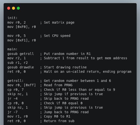
The assembler not only saves you from having to literally thumb all of your programs in, it also unlocks powerful pseudo-instructions such as goto and gosub, which combined with the ability to label sections of your code, is a transformative kick in the pants. There's even some provisions made for storing and recalling graphics data, a welcome capability for anyone looking to bring some games to the badge.
But whether you chose to switch over to the assembler and enjoy a slightly more modern software development paradigm, or stick with your trusty thumbs and LEDs that can tell no lies, the important thing is that you keep on hacking.
2022 Hackaday Supercon 6 Badge Guide
This is the starter guide for the 2022 Hackaday Superconference badge, designed by Voja Antonic.
 Lutetium





Discussions
Become a Hackaday.io Member
Create an account to leave a comment. Already have an account? Log In.