-
Front end input impedance for high freqs
11/16/2022 at 21:52 • 3 commentsAnother situation with which I found doubts was in the design of the filter at the entrance. If I remember correctly, to get a high input impedance, I used a resistive divider, which also increases the input range. The problem is that with this relatively high impedance, at high frequencies, the opamp had a lot of losses.
To avoid this, I put the capacitor C28, which is driven at high frequencies and allows to drive the input of the opamp. Again I have my doubts about this decision and I wanted to know your opinions.Is it bad architecture? Are there other solutions?
-
Power rail of mixed signal parts
11/14/2022 at 19:00 • 2 comments![]()
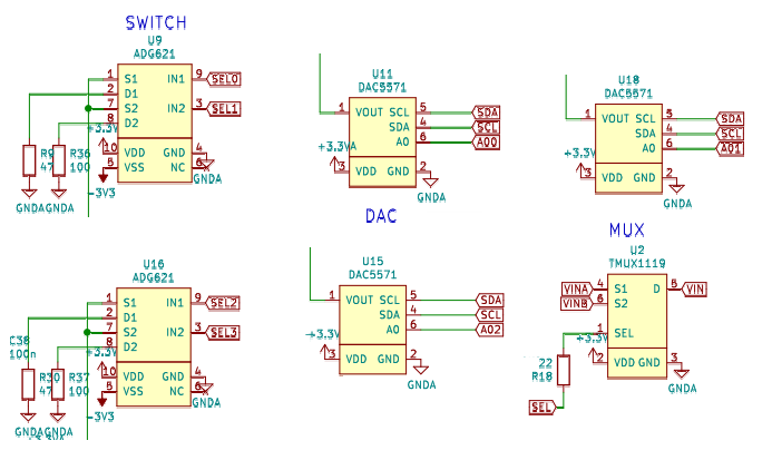
Similarly to the division of the power planes, I had some doubts about how to feed the mixed components and after several turns in the final design I see that they were a bit wrong. First of all, I don't have a clear criterion of what to do. I tried that the components with some digital signal were fed from the digital voltage, so as not to introduce noise to the analog one, but maybe that was a mistake, or maybe it is not important, but in any case I would like to clarify it with your help.
In the image above you can see several mixed components, EACH ONE WITH A DIFFERENT PATTERN! and I think this was a mistake caused by the rush and the desire to close the design and the BOM.For example, in the case of the SWITCH, which has positive and negative power, it is clear to me that they have to go to +3v3A and -3v3A, but in one of the cases, U16, it is wrong :-(((
In the case of the DACs, U11 goes to +3v3A and GNDA, but U18 (which should be the same) and U15 go to +3v3 and GNDA, which I don't like at all. Same for the MUX U2...
The power did not cause any problem, but it is a bad design decision and above all it reflects a rush to finish.
Finally, what did cause problems and I had to fix, were the I2C tracks, many of which are inverted. I think I copied the connection order from the PICO and never checked it. Pay the price by having to cut and jumper the tracks on the actual PCB. -
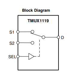
A better alternative for TMUX1119 is needed
11/10/2022 at 20:24 • 2 commentsAlternative TMUX1119
![]()
Now that the project has gained some audience I have the option of going to the community in search of solutions. So I'll tell you what happens to see if with everyone's help this problem can be unlocked.
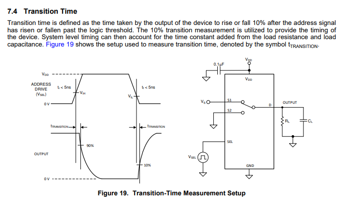
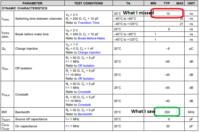
After making the design, playing with the input stages and writing a bit of code, I was ready to test the two channels with the multiplexer. To my surprise he hadn't taken into account a parameter that limited (indirectly) the switching frequency between both channels, and if he couldn't switch fast, he couldn't use both channels at the same time without sacrificing BW or SPS.
![]()
![]()
Does anyone know of an alternative with a shorter switching time (t_tran)?
Preferable in the same package and pinout, but I'm not hopeful... a new PCB is needed anyway to fix other small flaws.
Datasheet: