 Peter Walsh
I have a selection of PCB header strips, in 0.10" and 0.05" and single and dual rows.
The 0.05" header pins align with the connector pins, so a header might form the basis of a suitable connector. Two single-row headers glued together have pins that are too wide, but a double row is too narrow.
Start with the double row header.
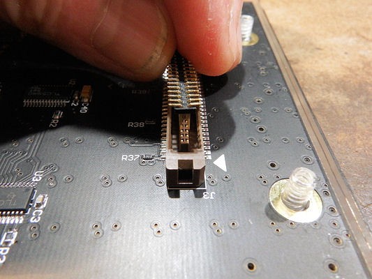
Now the pins are too narrowly placed to mate with the connector pins, but if we bend the pins out just slightly it might work.
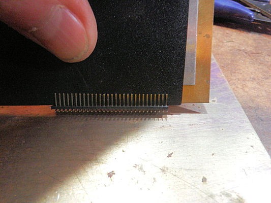
After some experimentation, I found that a thin piece of brass and a thin piece of plastic would fit between both rows of headers. Then a thicker piece can be pressed between these two, and the header pins gently bent outward.
Shown below is the brass (yellow), thin plastic (black) and a thicker piece of aluminum pressed between them. The aluminum piece is too thick to go between the pins, so pressing down on it causes the pins to splay outward.
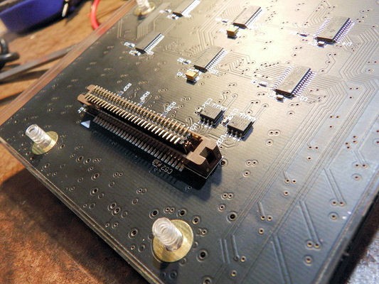
And... that works. With the leads slightly splayed, the header fits into the connector slot and the pins make contact with the header pins.
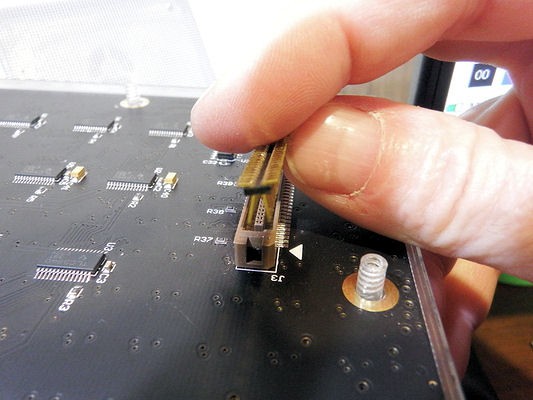
Testing a few of the pins WRT the header shows good contact everywhere.
Discussions
Become a Hackaday.io Member
Create an account to leave a comment. Already have an account? Log In.