charliex
-
OpenCV3 + webcam/camera
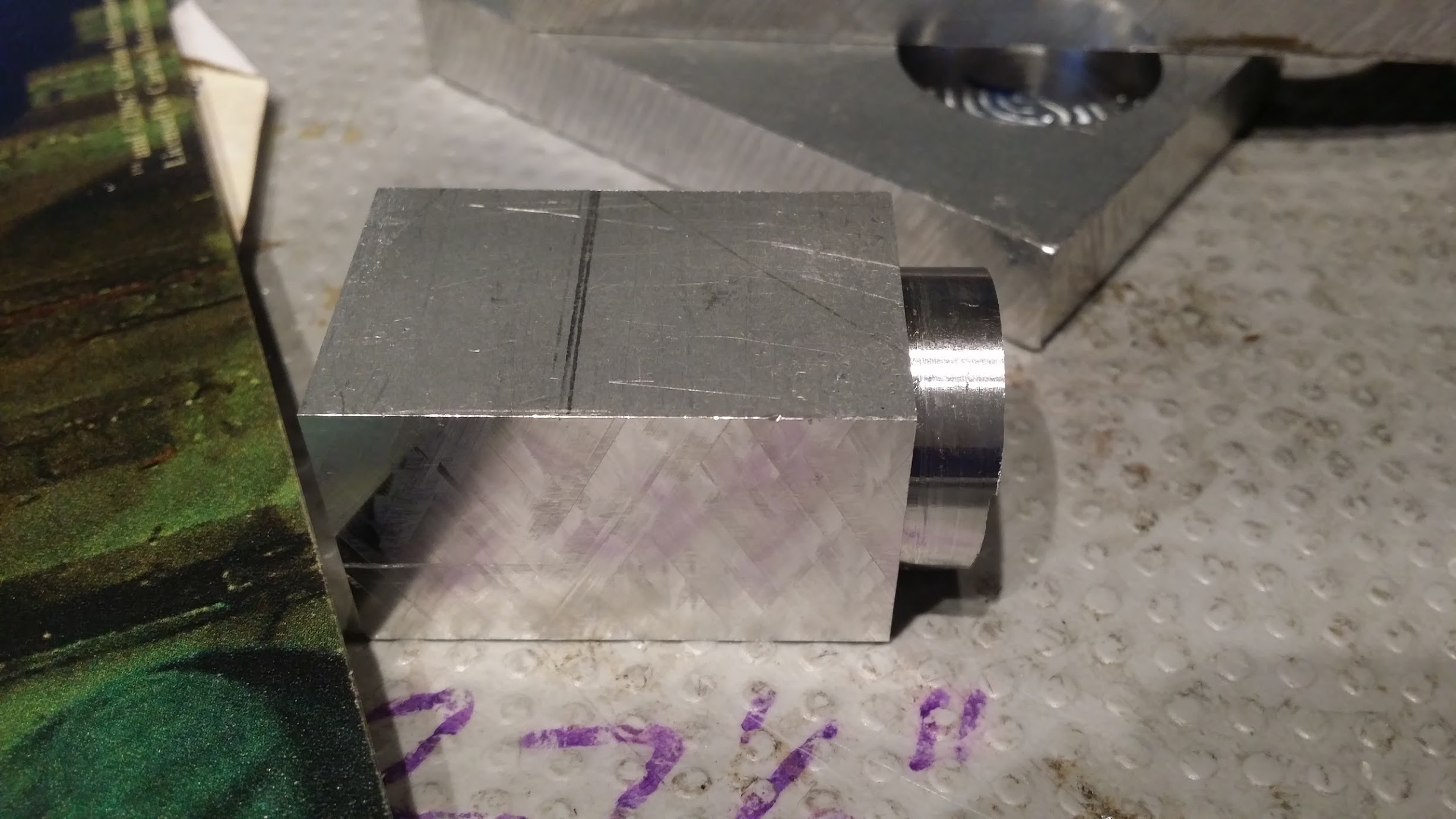
11/23/2015 at 16:54 • 0 commentsStarted playing around with OpenCV3 to see how well i could get it to measure holes and distances from a webcam (using a calibration object or telling it the distance) spent a few hours on Sunday with it and this is how far i got with it. HoughCircles + various filters, it'll detect tri/rect/circle/squares
The object is the top of the Z axis column.
-
Installing the Z axis.
11/22/2015 at 20:38 • 0 commentsFinally started the Z install.
Removed the flashcut motor mount, and the removed the two retaining nuts at the top, one jam. they come off easily.
the collet tool i use on my CBeam machine fits perfectly.
Undo the head bolts, but don't remove them yet and rotate the head. I put a block of wood under the motor to hold it
the two bolts in the middle there are what connect to the Z axis platform and the lead screw. remove these, loosen the head bolts and the lead screw will just pop out . the mount to the head is a two piece part. so it comes away easily.
Removed the manual jog wheel, just a few bolts on the side and it pops out.
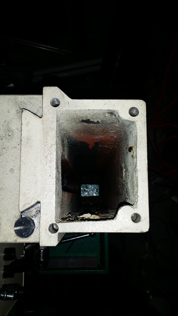
the old lead screw and z axis connector, the circular part fits in the front block which bolts to the z axis gantry. it can move backwards and forwards and fits inside a key way. knowing this earlier would have been useful
the hole left behind
so here's the first indication we're going to run into issues later, look at the hole patter its not even close to what it ought to be the top z plate has a lot of clearance and it can move around a lot, the M8 bolts slop around. note the bottom left hole is so far off its actually visibly cutting through the casting in the hole. . I used an internet attained internet PDF for those hole positions, welp (and pardon the irony) information off the internet isn't always accurate
bolts removed
remove the head , the three outer bolts sit inside a channel, one can fall out into the column , not hard to get it out but take care here. lift the head away then slide the z plate up and off.
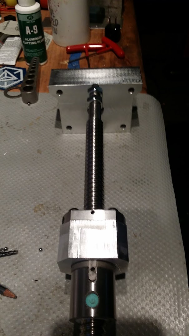
to put the ballscrew and the ballnut to z axis plate mount in there, we dropped the nut into the machined mount and held it there while adding the four bolts, its fiddly but you can't really install it whiles its mounted to the ballnut
later one we'll discover this forward distance is quite important and the mounting bolts in the top plate being off will cause it to bind at the top, so we ended up superglueing a couple of small belleville washers to the front of this to give a small spacer of about 2.7mm, since we can then change the gap with the pressure on the bellevilles it means we can test it later and let the machine pick where it wants to be, before bolting it all down.top plate mounted (with only one M8 bolt), than ran it up and down a few times to let the ballscrew settle into place with no binding.
and here's a test of it unloaded, moving at 100 IPM , which is the limit i set in the controller
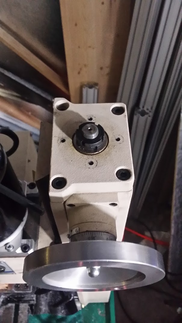
we didn't have a pulley for the ballscrew z, and the old one had center hole too large so onto the lathe to make a brass insert with two holes for the allens to go through. didn't get photos of that operation though.
ended up ordering some off ebay, that had flanges and about the same build quality as our drill press version.
back together and leveling out the table, manged to install it with .0001" off! but of course when we tightened the bolts down it moved as expected, so tram with a mallet time..
testing the backlash, tested out to .009" on the first go, which is when we had to go back , find the binding, realise the mount holes were so far off , mark them out and then remount it all with only one bolt, so have to recad that Z plate mount and plate again. So for each mount i'd check the machine first, or use slots in the mount. we didn't preload the double nuts with bellevilles on the Z so the backlash is higher than we'd like, but still much better than it was. Having the max speed go from 15IPM to 100IPM is worth it.
i have the china/ebay quick tool changer things in ER20A with collets that were about 1.99$ each !
Super!
Super Precision 14 PCS 1/16"-1/2" ER20 ER-20 Collects Set With 1/8 1/4 3/8
New 10pcs C3/4 ER20A 1.38" Collet Chuck Straight Collet Chuck CNC Milling Lathe
the holders are decent, the collets are OK but since they cost just about the worth of the metal, i'll upgrade them as we go along.
also picked up this one way bearing on a pillow block, its used for mounting the tools into the r20 holders when its off the machine, insert and tighten, then flip to the other side to loosen. tormach sell them but they're probably available elsewhere. the ebay pulley is in the background too, we're doing 2:1
the holders and collets arrived in a few days.
unfortunately i had to run off to ER as we were about to cut since my gpa was admitted again (he's ok). but mmca managed to cad up a 2.5/3d cut cone to test the new Z axis.
-
Z mount
11/01/2015 at 16:29 • 0 commentsMade the top plate of the Z axis mount, and face milled off the rest of the Z mount.
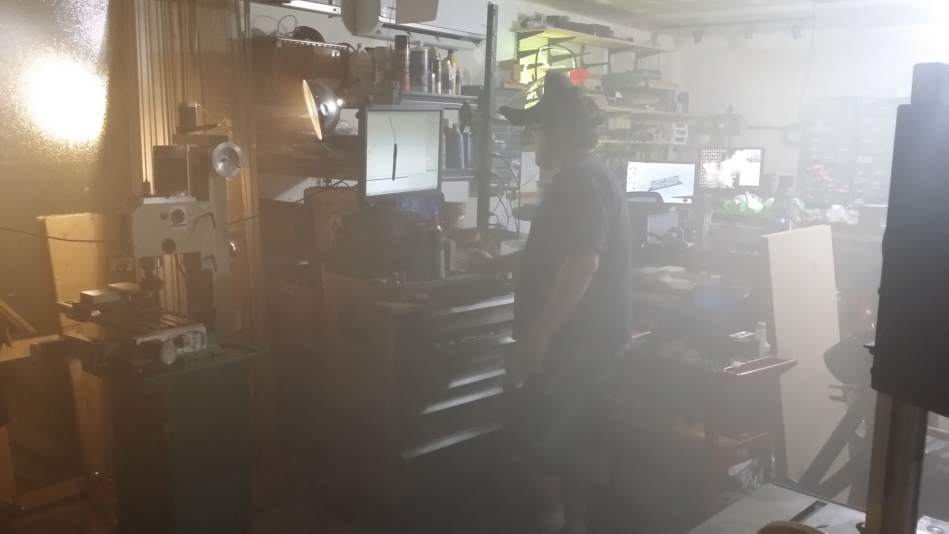
Don't CNC during halloween, here is mr pika running a facing operation.
i was running the fog machine outside, the garage filled up.
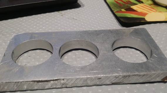
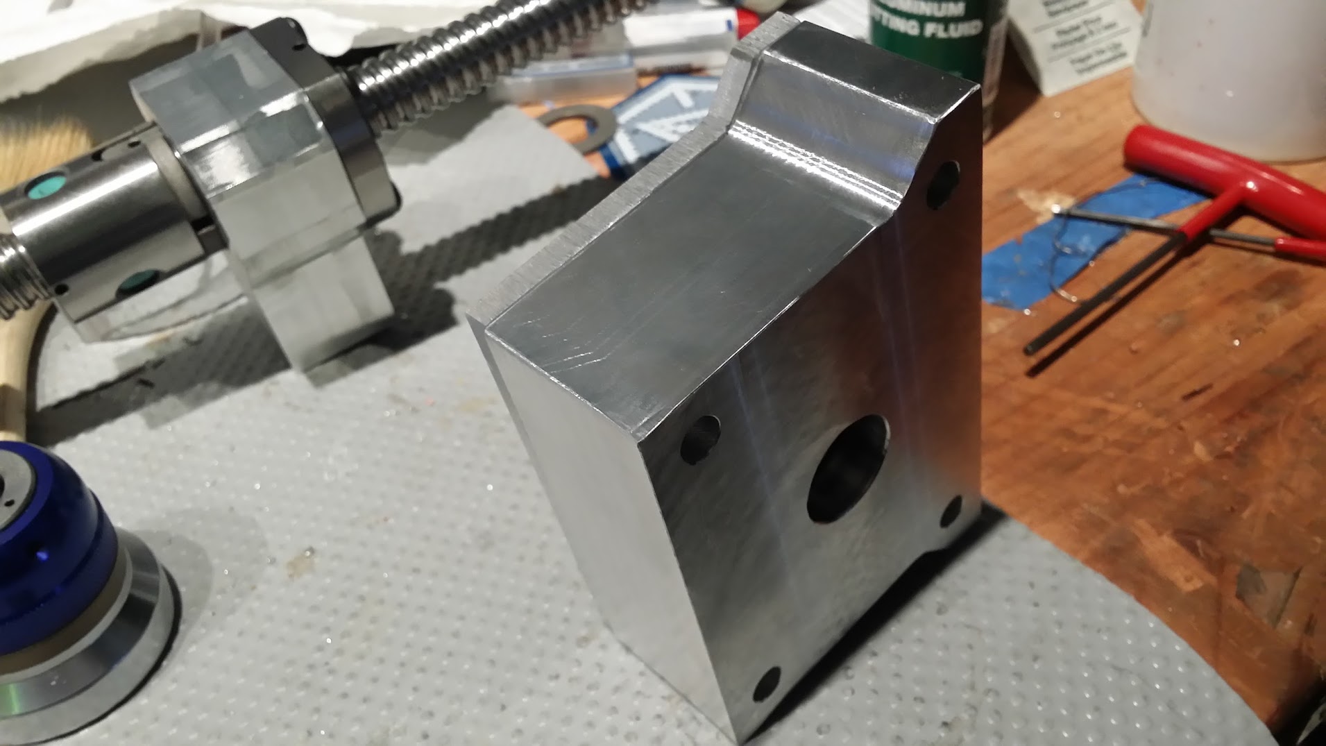
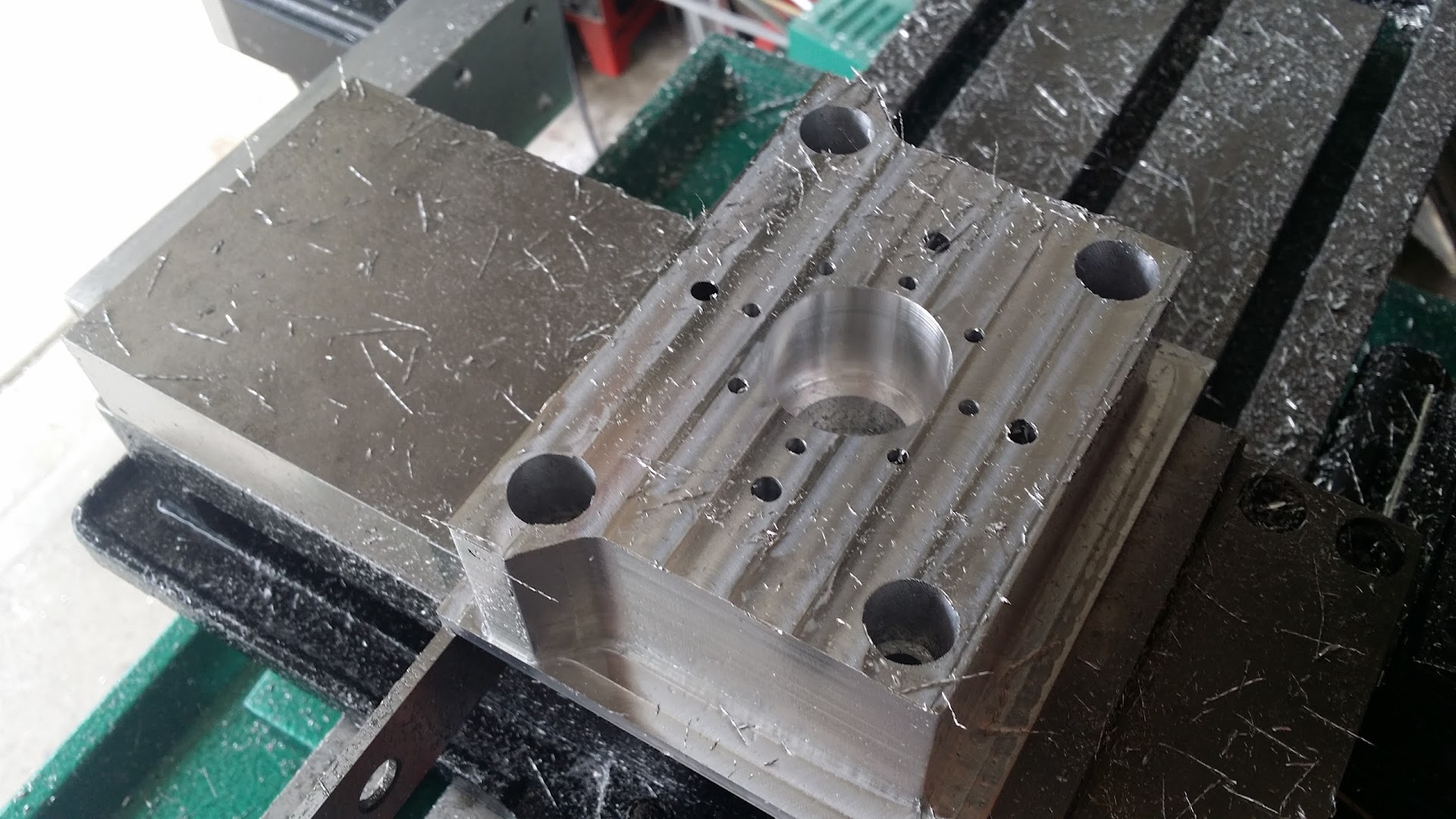
I bandsawed the outside of the top plate, using a piece of metal as a guide, that metal wasn't straight so i miscut the left side.. on otherwise a nice part, we did break one drill bit because the stock was slightly deeper and disagreed about readjusting the Z 0.0 adding on the difference etc, instead of just redoing the CAM, the answer was of course redo the CAM since the retracting was a fast partial retract so it clipped the edge of the hole and snapped. You can see it on the inner circle of holes middle left,. shame since the part had a mirror finish on the mating side after a face mill. but its all luckily cosmetic and the idea here is to build parts that are better than the existing ones, then redo it all again. There are three 31mm bearings inside the centre hole.
it'd mounted nicely to the ballscrew with an interference fit after very slightly knocking it down with some 1000 grit.
We're ready to mount the part now and see if it all fits. here's the A360 of the latest model http://a360.co/1GdnYAf this is the Z plate and mount. We need stronger belleville washers, so didn't get to fit it up, should be next week.
After that we may move on to a motor update or extend the Y axis, the current motor is only good for about 0.2HP/149N/m.s which is pitiful. Looking at a 220VFD with a 56C frame motor.
The Y axis is longer ballscrew, put the stepper on the back of the machine, add a two inch block between the table and column, and a 2" , 5" diameter round stock on the head.
been buying these bearings
-
video of z plate cutting
10/30/2015 at 03:24 • 0 commentsthere is a strange cadre of people out there ( i'm one of them ) who'll sit and watch a video of a machine cutting something, even something this simple
-
compressor notes
10/26/2015 at 00:09 • 0 commentsSo since i added the 30 gallon noisy-ish compressor a few days ago, i thought to myself i'll just install it next to the CNC for the moment since that is the noisy/messy corner. When installing it , i put it on the same circuit as the CNC's motor while thinking, i should remember to move this since if they both run at the same time they'll pop the 20A fuse..
So of course next day, we start running up the mill, i'm CAD'ing, mmca and mr pika are working the CNC. I go in the house and to grab something and i hear a lot of air, sure enough the fuse has blow, cnc is down, pc is down, compressor is full of air, my pc is also down. . aha right that 20A circuit, after resetting the breaker and moving the compressor to a different circuit, and making a mental note to add UPS's all over and separate all the PCs ( and cable modem/routers) to a different circuit. We were off again.
So we're cutting away and of course this machine is a new build, so its prone to things going wrong and we're usually watching it while it cuts. Since until now we've been using canned air as we are ecologically friendly, imagine when a fairly large compressor kicks on about a half a metre away from you, heart attack time which isn't good since both my grandpa (wife's side) and my brother (my side) are in hospital for quad bypasses and other heart issues.
So I figure after the part is done, i'll relocate the compressor out side for it.
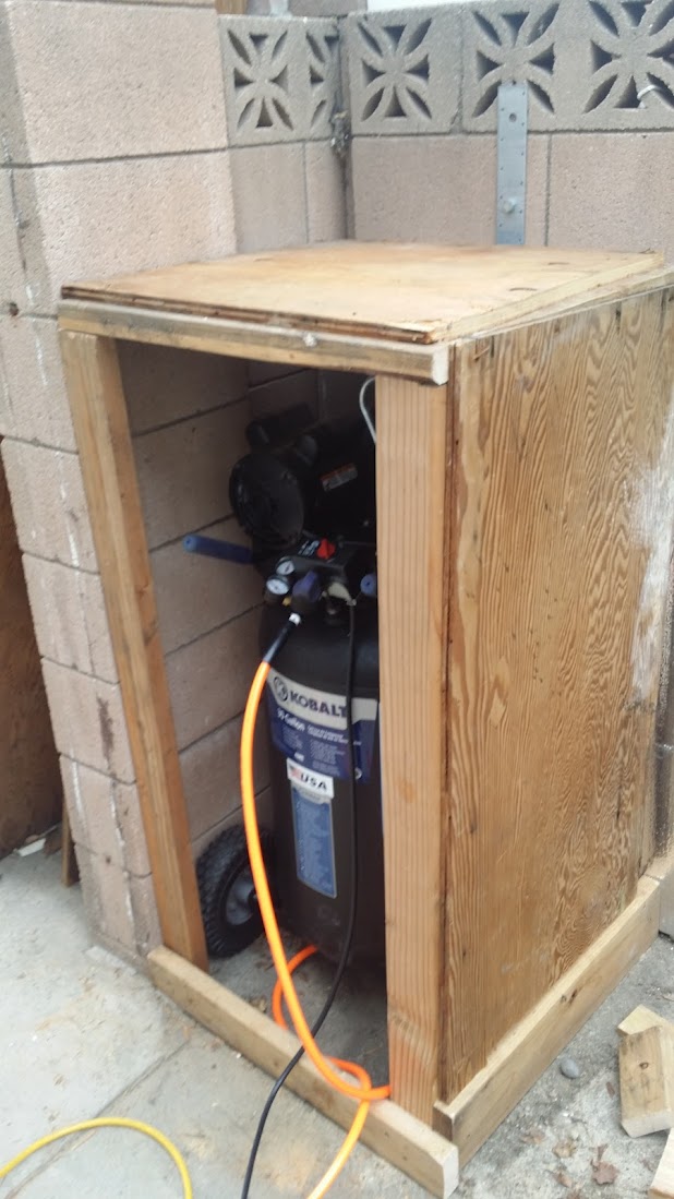
I had some old wood lying around from shelves that were in the garage before we moved in. So i built a hobo shed for the compressor, ran some 300 psi tubing for it and mounted it. I'll change it out to black pipe when I've got it settled as to where it will all go.
Hobo shed, sawzall, scrap wood and some screws.Even though I've got some nice wood working tools I used all the crappy ones. 5 minutes later. I'm sure the neighbours regret buying that rooster last week.
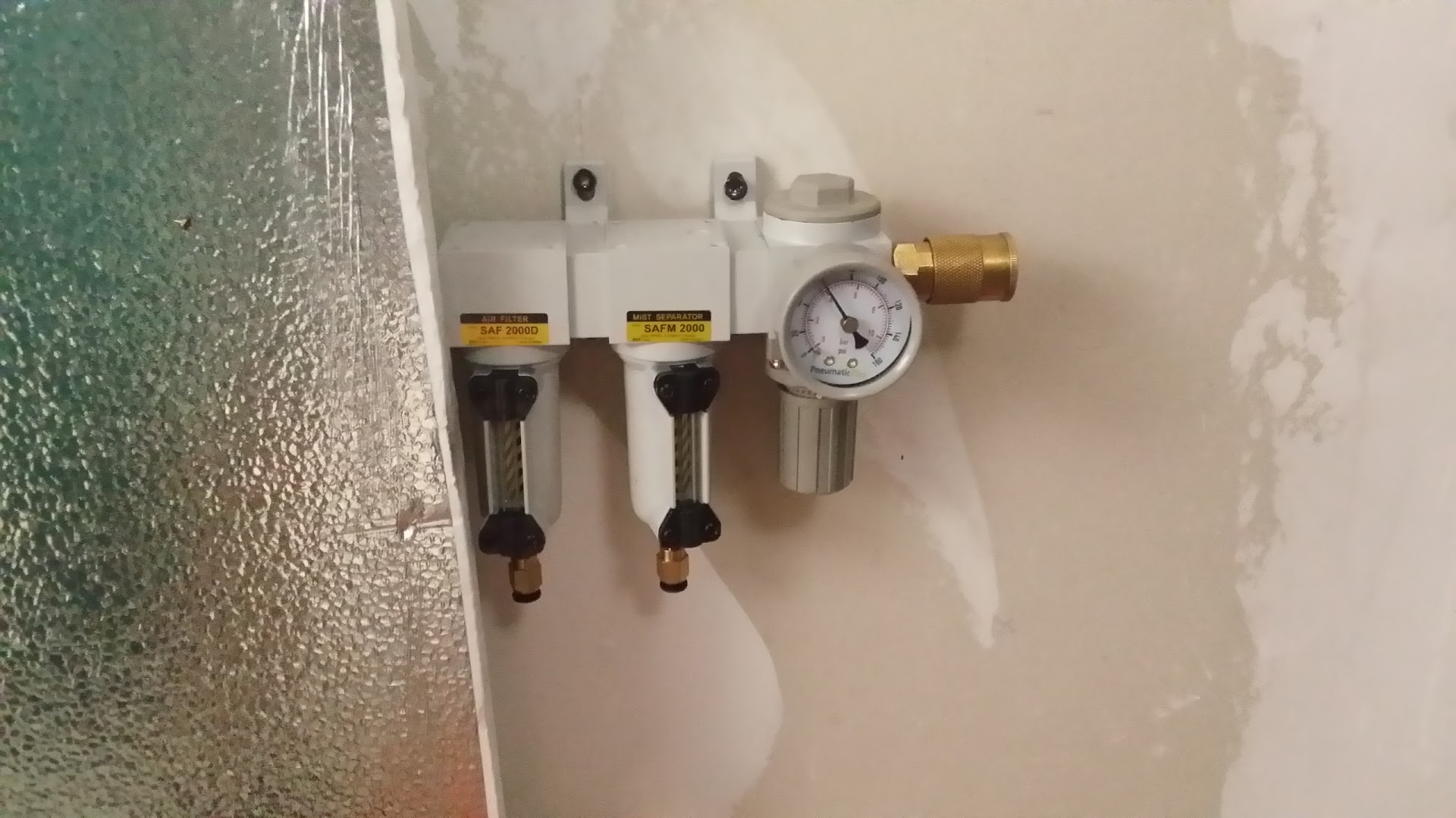
mounted the dirt filter/moisture trap inside the garage with a quick connect.
great, that'll work for now and hopefully no more WTF what was that when we're doing delicate machining etc. I should know better since when i first started air brushing i used a noisy compressor, and while i was painting it'd clatter to a start usually making me jump and paint stuff that wasn't meant to be so, learnt that lesson and bought a supersilent 20A for that many years ago.
Compressors are usually fine outside even in the heat, the motor and compressed air is a lot higher temperature than most ambient temps anyway. I left gaps in the front and back for airflow and i'm not permanently running it, just when i need it. que horror stories from some , and others with the I've had my compressor under my bed for 100 years with the wife , four cats and a subway franchise and its always been fine. It is oil based too.
-
Z column top adapter.
10/25/2015 at 21:20 • 0 commentsMilled out the top part of the Z column this plate goes on the top and holes the bearings for the Z ball screw.
Created and CAM'd it in Fusion360. http://a360.co/1GdnYAf Design is there, though be warned haven't test fitted it yet. Took about an hour to cut out of 7075-T6 aluminium with two drill bits 1/4" and 1/2" end mills. Bought the bearings from alibaba they were nicer than local sourced , claimed ABEC5 rated. The last ones we got had laser marks showing the high spots, but who knows.
We're using two bearings at the top + a spacer, the spacer is the outer race of another bearing, yep we use bearing races instead of precsion washers/shims.
Came out decent.
Getting close to adding some sort of collection tray/enclosure.
Also finally picked up a compressor so no more canned air , added an electronic solenoid + SSR to allow it to be controlled from the master control box. Used this solenoid control which is 110V.
cad'd up the top plate that holds the bearings too, that is in the file linked above in A360. Next steps are to cut that out, run a boring bar over the bearing hole in this adapter and i guess we'll try to fit it.
-
Cutting out the Z ballscrew holder.
10/18/2015 at 18:39 • 0 commentsStarted on the Z ballscrew holder.
So we started cutting full depth with 0.375" end mill and it looked like it was going well, there were some odd looking rapids and sure enough the Y axis was slipping. After a few tries and dropping the speed and DOC it was still dropping, so we looked at the machine setup and for some reason the rapids had been changed from 2 in/m^2 to 200 and 500 for cornering, which is impossible on any machine so its odd you can set that. So once that was fixed it went off to cut, Unfortunately the gopro battery died after all the messing about and it missed the aggressive spiral helix and circle cut.
once we put it on for first fit, it didn't quite slide the whole way, forgot to break the edges. So after that it went on perfectly. this is really the first part we've done as a fully CNC part, no bandsaw or drill press ( though we do have to add two holes on the back eventually)
now i'm finishing up the Z plate and we'll cut that next.
-
Reducing the backlash
10/11/2015 at 18:39 • 0 commentsPulled the XY table apart again down the ball screws and removed the double nut and the brass shim, replaced it with some 18lb belleville washers, added some other washers to the, also used an inner race from a dodgy bearing instead of an aluminum spacer to help it be flatter.. This reduced the backlash to X0.0002" Y0.0006" , so of course next thing was to cut two test circles, an outer and an inner.
turned out great, it was slightly undersized so redid the gcode to add 0.14mm to the 30.01mm hole we wanted and it came out at 30.01mm in the X., the Y was slightly over, around .045mm
outside circle cut
surface quality is great. this is a small helical arc down to 0.3" at about 20IPM with a 0.250" end mill, then does a depth of cut of 0.3" to the outside with one finishing pass.
Pretty great, and a world of difference from the first circle we cut, which was a circle only in the loosest of terms. When the bearing is installed, one side has a .045mm gap, which is the over cutting. but it sits tight otherwise/ There are now so many pieces of metal on my bench with circles cut in them.
I think next we'll do the Z (which even with the lead screws is doing well ) then change out the motor.
-
Testing out the Ballscrews with circles
10/04/2015 at 22:29 • 0 commentsCircles are hard to measure, and hard to cut. I have specific tools just to measure circles telescoping gauge and tools to help cut them on the CNC boring bar . But cutting them out as circles from GODE is a good measure of how well the CNC performs since it tests lots of things at once, how smoothly its moving during a cut as any poor motion will show up in the surface finish., backlash shows up as flat/high spots which will appear at the point an axis changes direction, or when a tool cuts since any cutting movement will take up any backlash before it begins to cut, just as a direction change won't actually happen til the mechanism for moving is in the right place.
Our first circles with the FlashCUT conversion kit, were frankly terrible they were more of a teardrop shape than a circle., since their kit relies on the stock lead screws.
We built the new parts to hold the ballscrews and switched to a belt drive instead of direct drive as a lot of the G0704 conversions have. Then finally got around to reinstalling and tramming the head and table.
Next step was to reconfig the software for the new movement, belt, pulleys and ballscrews.
Then finally able to actually do a circle cut.
And here it is. The middle one was an aborted cut. Take a look at the finish quality.
and a shaky video of it doing the cut, a healthy amount and size of chips coming off it, cutting at 3200 RPM at 20IPM. The machine is considerably quieter and more rigid (mostly to do with the resetup and rebuild of the gibs)
There is some recutting going on , thats where the chips aren't cleared away and they end up under the surface of the cutting edge again, it marrs the surface a little bit. Also doing one spring/finishing pass , this accounts for any bend in the tool when its cutting a lot of material, it does a very small skim pass removing none to a very small amount of material.
We're still about 0.0019" backlash so a little bit to go, but its a lot better than it used to be.
here's an older video of it cutting with lead screws in a circle/diamond square test, you can see that part in the above video we used it inside the machine to stop the ballscrew nuts going to far, so wasn't wasted, but the flat spots are much more obvious
it can move at 150IPM now.
neato. now to just chase down that last bit of backlash and then attack the Z, convert that to ballscrews and add spacers to increase the Y , hoping to get 200mm / 8" of travel.
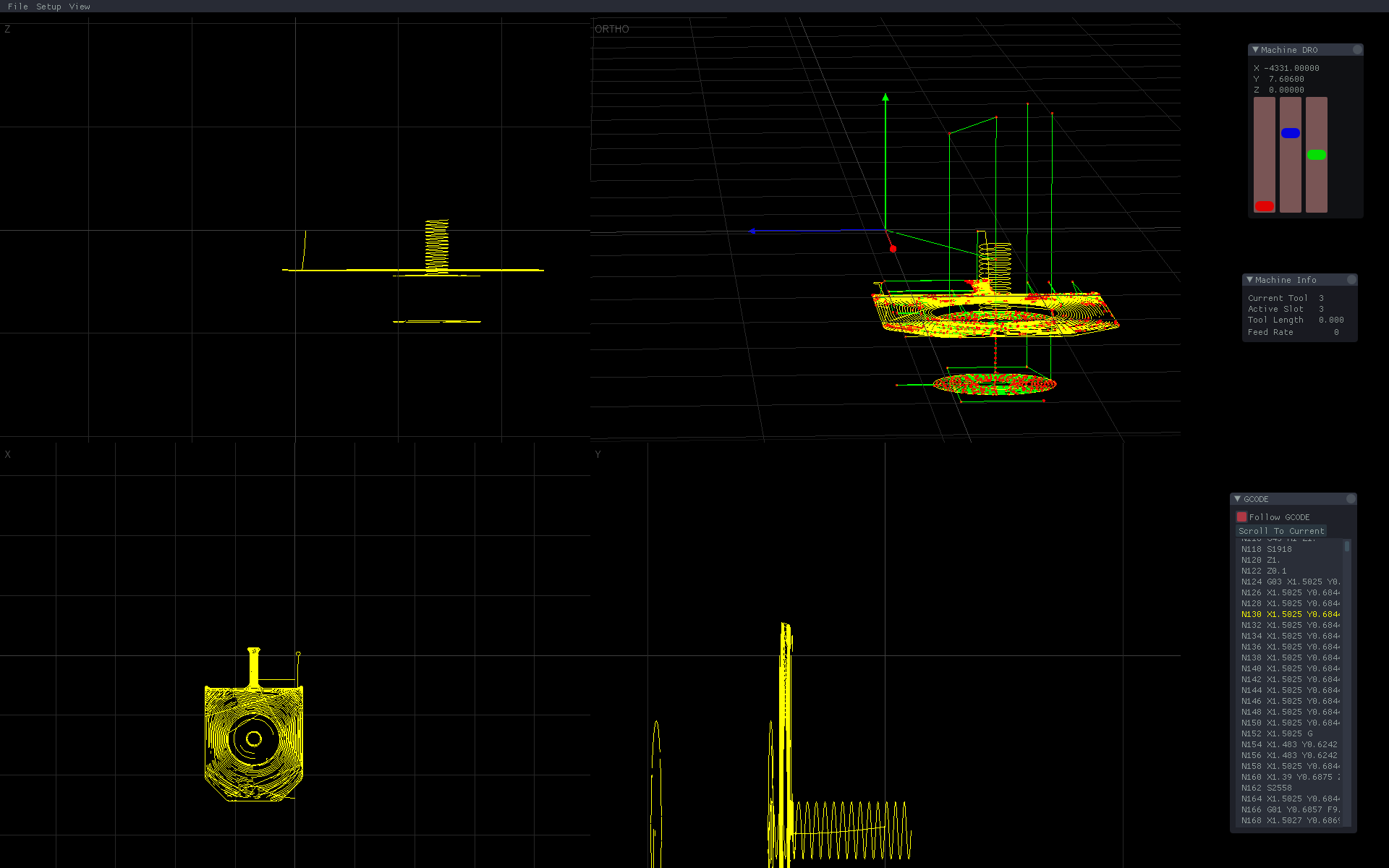
oh and is usual, i also got fed up with the flashcut host software, so i did what any of us would do and started to write my own.
Using Cinder + imgui for the UI. It's coming along.
![]()
-
Installing the Y axis ballscrews.
08/30/2015 at 19:06 • 0 commentsmade the Y axis bracket on the C-Beam, later on turned out i didn't have any M6 80mm bolts so we hastily cut it out of 1/8" acrylic. I also forgot to take off the "leave stock" option, but otherwise the holes it cut were the right size and decently round, so that's a start. I'm going to recut it in steel today.
initially with the pulley blank from amazon, we lathed out the hole to fit on the ballscrew, and added a hole for a set screw which fits on the flat.
mmca then lapped and scraped the gibs, i didn't get a lot of info on this one, but there are lots of videos elsewhere and he is skilled enough to do it by sight, basically hi-spot dykem and a granite plate, some laps and fine wet and dry paper.
test fit, so far so good. this is the large slot we routed out manually with the C-Beam and the dewalt 611.
after adding the x table the double ballnut was scraping the underside of the table.. sigh yet more grinding of the cast iron, not fun, i wore out the dremel battery and me, my fingers are still vibrating a day later.
fixed that mounted the table and X and Y motors onto the pulleys.
you can see our shame in the yellow acrylic, also note the direction change of the pulley, we had some discussion about how to do it, eventually went with putting the set screw into the teeth and countersink/deburr and it lines up nicely. we talked about removing some so it'd go over the threads, and even putting a thread to match the thread of the ball screw ends.
set the software up to do 5mm per turn and 2:1 ratio on the pulleys 10/20T.
after some testing we say about 0.003" backlash, which was disappointing, so some fiddling around testing and retesting and discovering flashcut can't do enough precision in its backlash compensation we moved on to look at why.
The double nuts on the ball screws aren't preloaded, which seems odd so basically what you have on the ballscrew with a double nut is two sets of balls in opposition to each other, so they're pressing up against the inners of the ballscrews themselves, that way when the direction changes there is no slack ours did have some movement so we fixed that with a shim
![]()
later on we'll try a belleville spacer etc.
after this , and some accidental switching of things, numbers weren't adding up, so after some investigation on why it'd step one but not the other, discovered the pulley setscrew on the motor was loose ( again) this has been common on the flashcut for me, so they need some threadlock.
once that was all sorted out the backlash was down to sub 1000th's/in ( sorry about the mixed SAE/metric)
got a move rate of about 140in/min, which is 100 more than the lead screws..
again the plan is to strip it after test fit and then put it back together with more pictures, we're in the test and see phase of things. for the boxes of screws i've picked up recently, the fact we're always missing some size is maddening, especially since its nearly all metric and local stores pretty much carry SAE only with a smattering of metric, i'd say amazon to the rescue but they're even on two weeks delivery for some of them.
next is to install the X axis ballscrew and we should be able to reassemble it for test runs before teardown again, and we'll probably tear it down again after that because we can remake the various mounts and so on.
Grizzly G0704 CNC Conversion
Joining the ranks of the Chinese made Grizzy G0704/BF20 conversions.


 outside circle cut