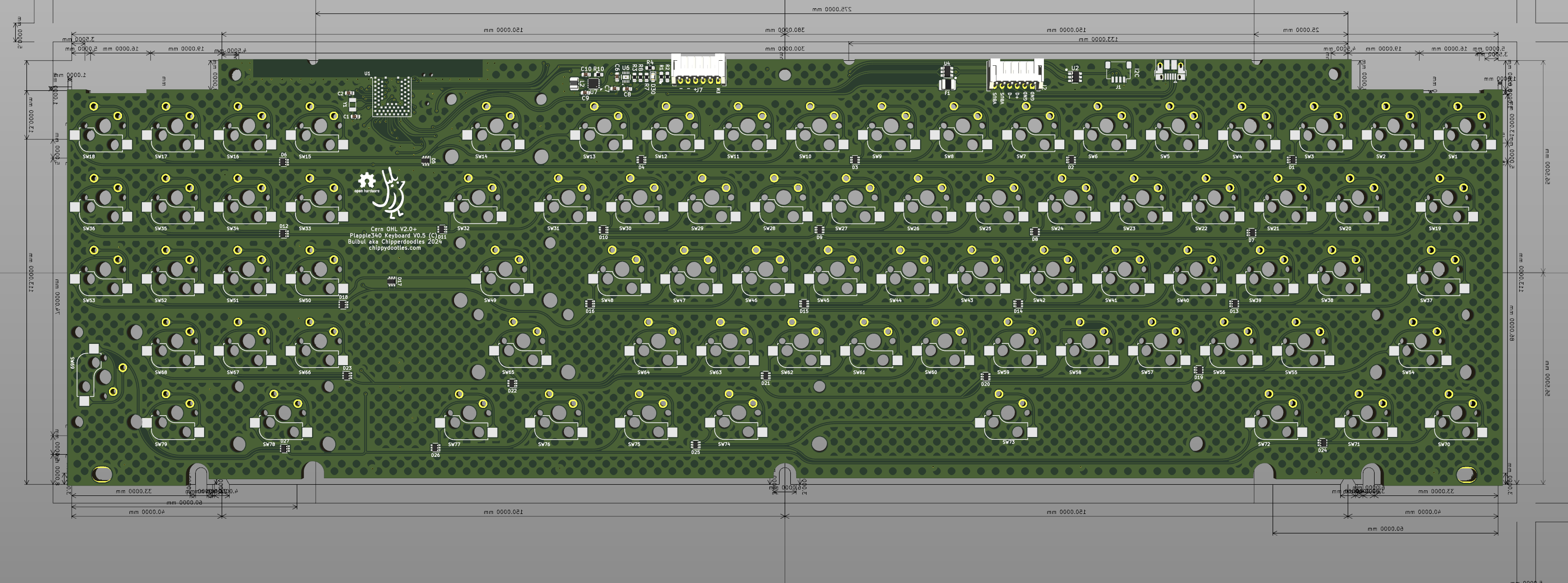
Today I've published the design source code for the PCB. I still need to work on cleaning up the usb adaptor pcbs and mounts but not sure when I'll get to that. But in the meantime here's the main part. It's still usuable as a standalone keyboard and provided in the source are dxf drawings for 2 different styles of plate/sandwich cases, as well as 3 different switch cutout options.
Hi! I know there's been a few people interested and i'm posting some progress I made today.
I've updated the connectors to 6 pin jst-ph for both the external battery and usb connections which means I'll need to redesign some daughter boards. Why the 6 pin for the battery? Main reason is I added another external connection for enabling the onboard voltage regulator. This will allow an external power switch to turn off/on the keyboard. Most Ble stuff is meant to be always on these days but there's just a comforting thought to know I can turn it on/off. Also by default I plan on using a single AA LiFePo4 so the battery charger is set up for that. You can use normal lion if you want but you'll have to change the resistor values if assembling your own. Other than the power path and breakouts the keyboard is largely the same. Same matrix and I haven't touched the switches. I don't have the money to test out the keyboard but I will probably be publishing files if anyone wants to give it a try before I get the chance. I may redesign it to have hybrid alps/mx for the solder on option footprint. cheers! I'll probably post an update once I clean up and upload the files.
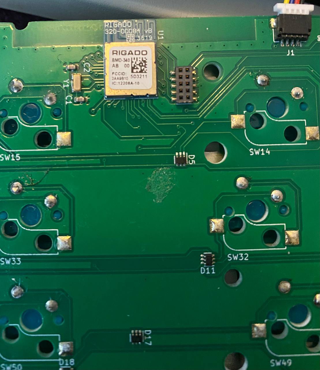
Backlog 3 brings us to the current revision of the board. I learned of the ZMK firmware which adopted a bluetooth first (but not bluetooth only!) approach to open keyboard firmware, they use Zephyr RTOS as the base for the firmware and i was delighted in how easy it was to make a custom board for it. It's also easy to maintain custom builds with their github actions fork that will build firmware for you when you change your keyboard files and push the changes. One of the most well supported bluetooth soc's in the maker ecosystem is the nordic NRF52840, this has been very popular for reasons of arduino support (and other firmware as well such as Zephyr Rtos), dev boards and modules available, and the fact it also has a usb peripheral making it a perfect match for a keyboard project.
I had a nice grab of about 20 modules from the free table of my old workplace. These were Rigado BMD-340 modules. (which were acquired in the past few years by ublox and rebranded ublox BMD-340 iirc). Since I had some I decided to take the dive and redesign the plapple board around this module, as well as why I didn't opt for the cheaper more common raytac modules.
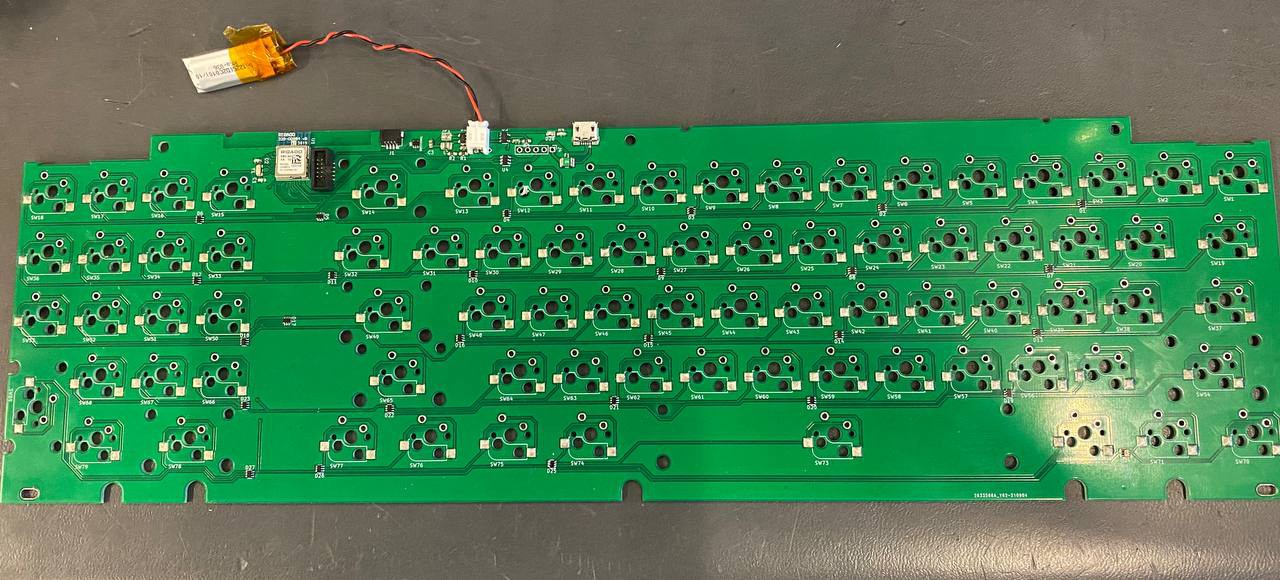
Design was simple, the biggest changes was needed to add a LIPO charger and a cut out zone for the bluetooth.
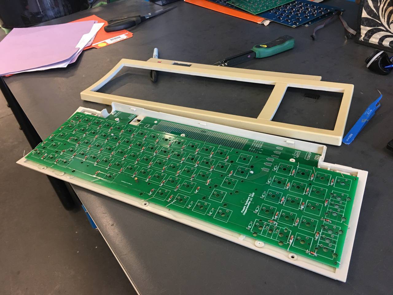
As you can see I also switched to surface mount diode arrays to lower parts count and to make it more smd friendly.
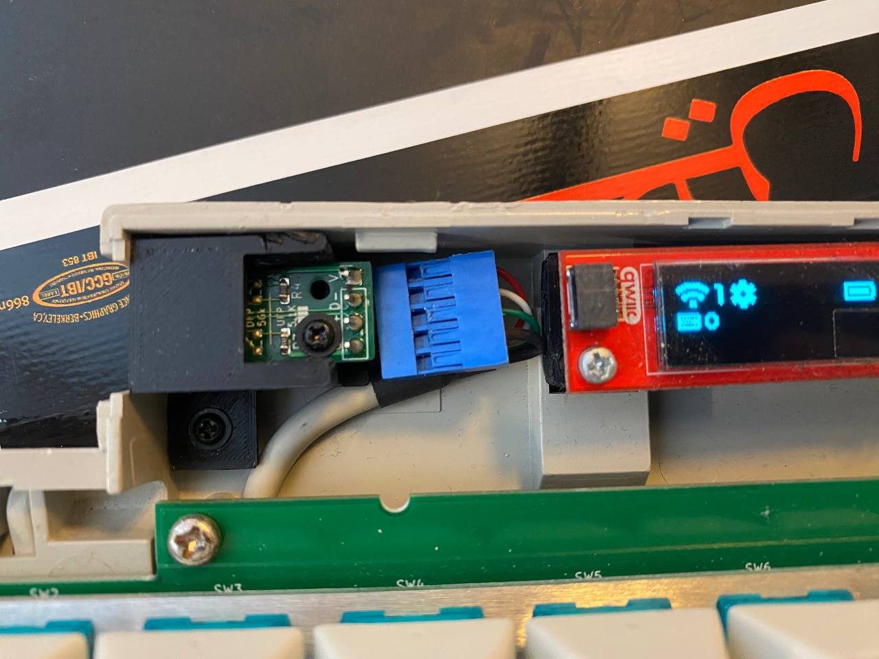
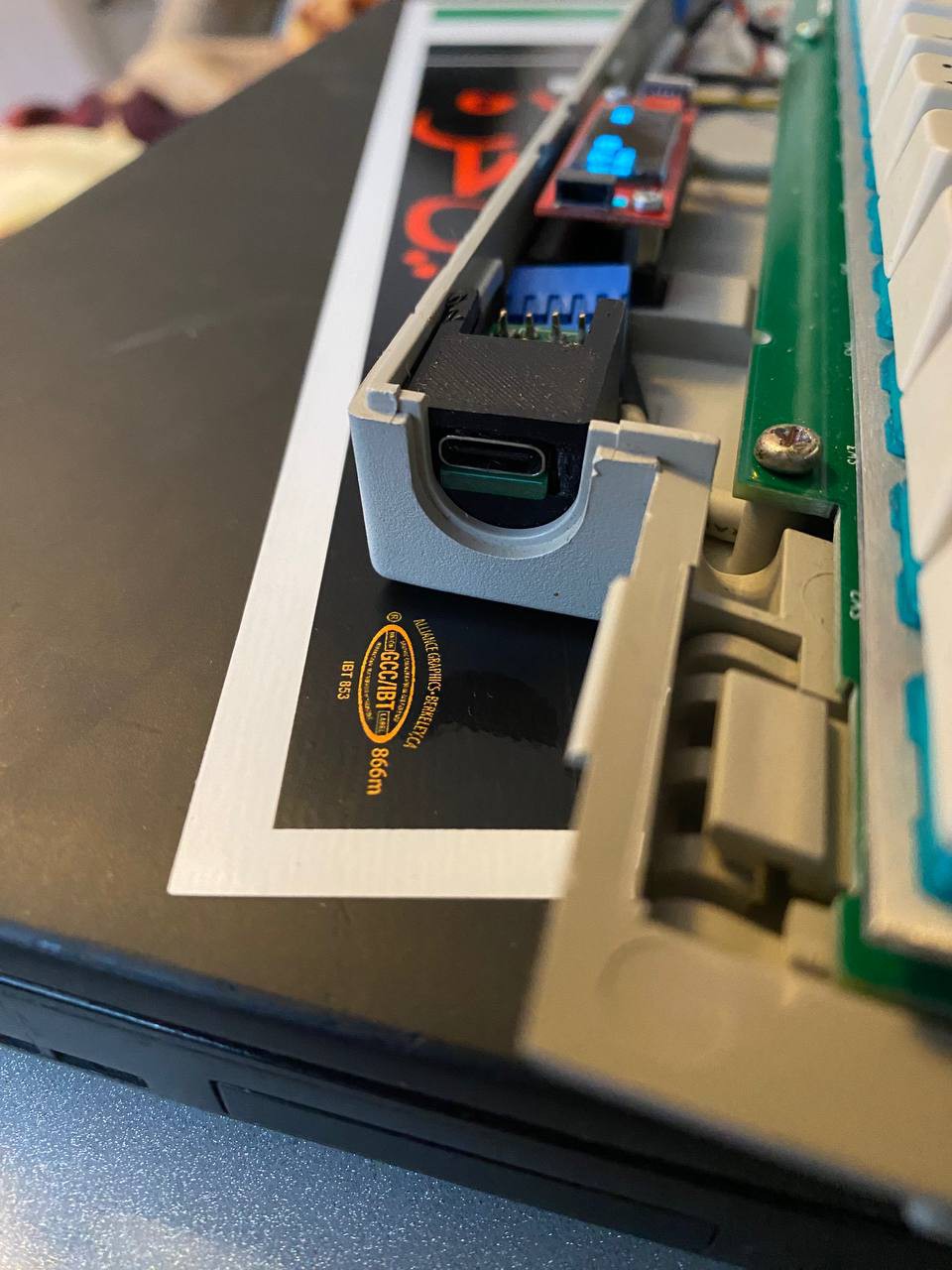
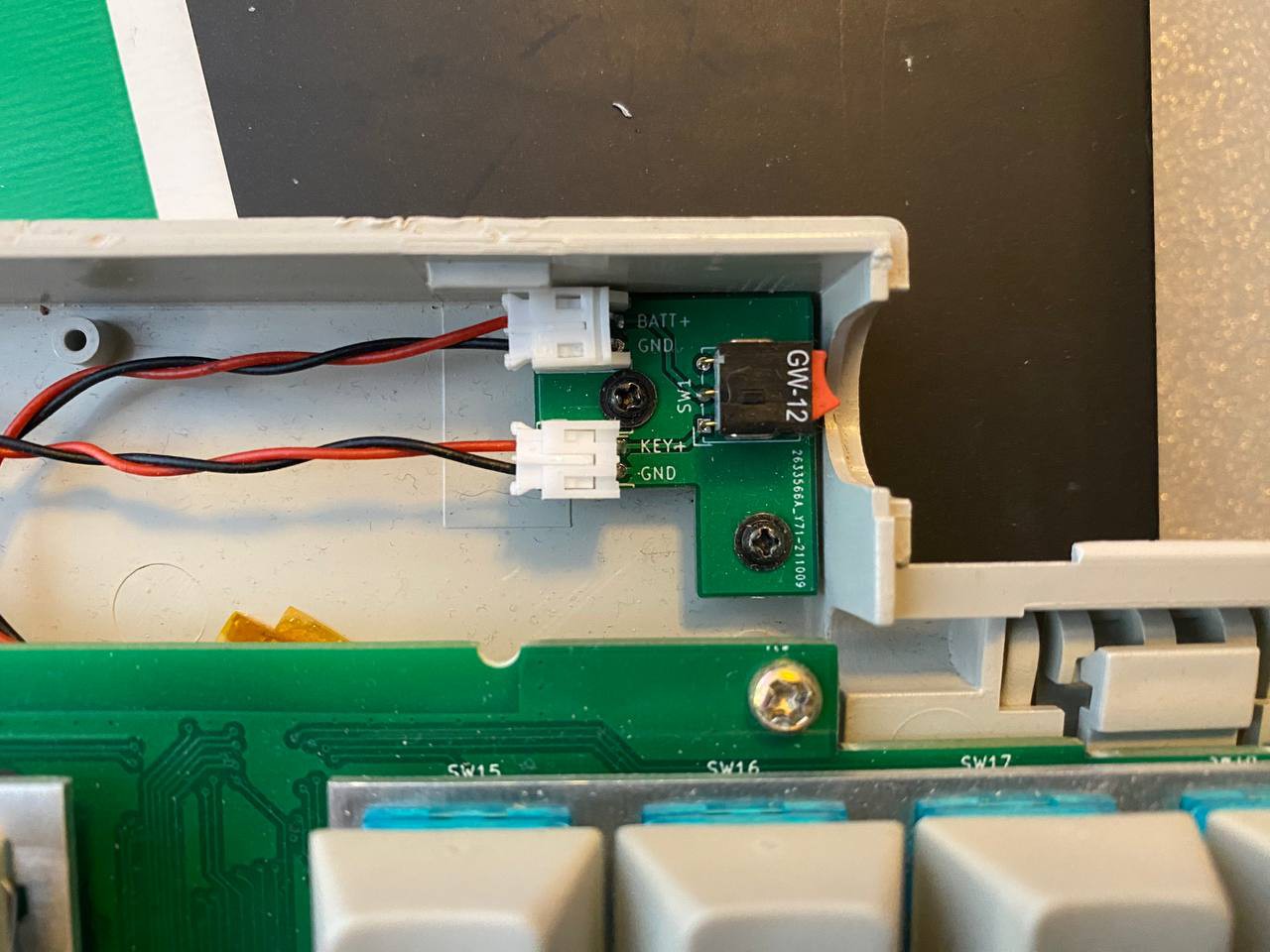
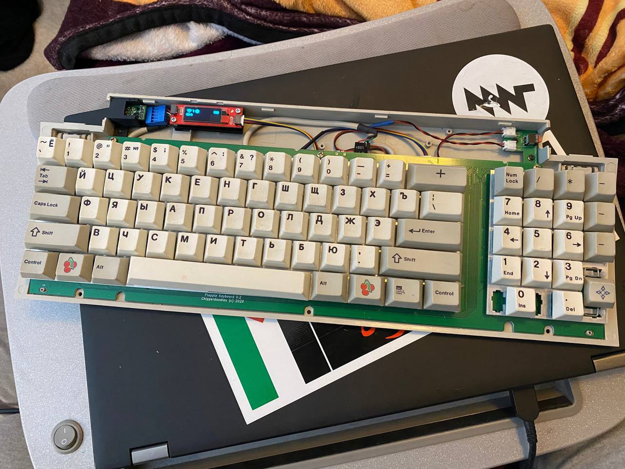
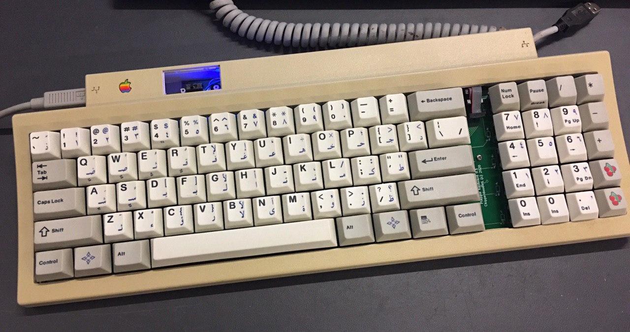
Outside of that and my many failed secondary pcb designs (the ones that fit where the old controller board would go) It was relatively painless. I improvised a simpler usb-c adapter for usb connection that relied on a 3D printed housing to make it line up where with the spots for the old mini-din connectors went along with a cobbled together a internal usb cable from an old pc case. I just need to adjust the 3d printed part to center the connector better otherwise, I'm really happy with that fit. For the battery connection I added an in between board for the battery with a switch to disconnect the load if the keyboard is going in storage. The circuitry on board only has a LIPO charger IC and no cell protection so the added safety of a switch as well as the mental reassurance that something is off when switched off felt like a good enough reason to add it. I had to splice 2 jst battery cables together to make a male/male cable to go between kebyoard and power switch board. For the display I used a little i2c SSD1306 oled and 3dprinted a (accidentally) press fit mounting bracket that slips around supports for the old apple power switch.
Not ideal but it works.
An important note, These little adapters for the power switch only work with the SMK version of the apple keyboard II case. This is because the SMK version actually had screw mounts for the old controller board, which allowed me to reuse them. The mitsumi case lacks the screws and it's controller board is a simple pres fit and held in place with some plastic supports.
So that leaves me with some things I still want to do before I call the project finished:
Re-examine Power draw
Re-design power rail/management
Add lipo cell protection IC (maybe add to switch daughter board)
design a succesful/functional full size daughter board
Change power switch to pushbutton on switch daughterboard
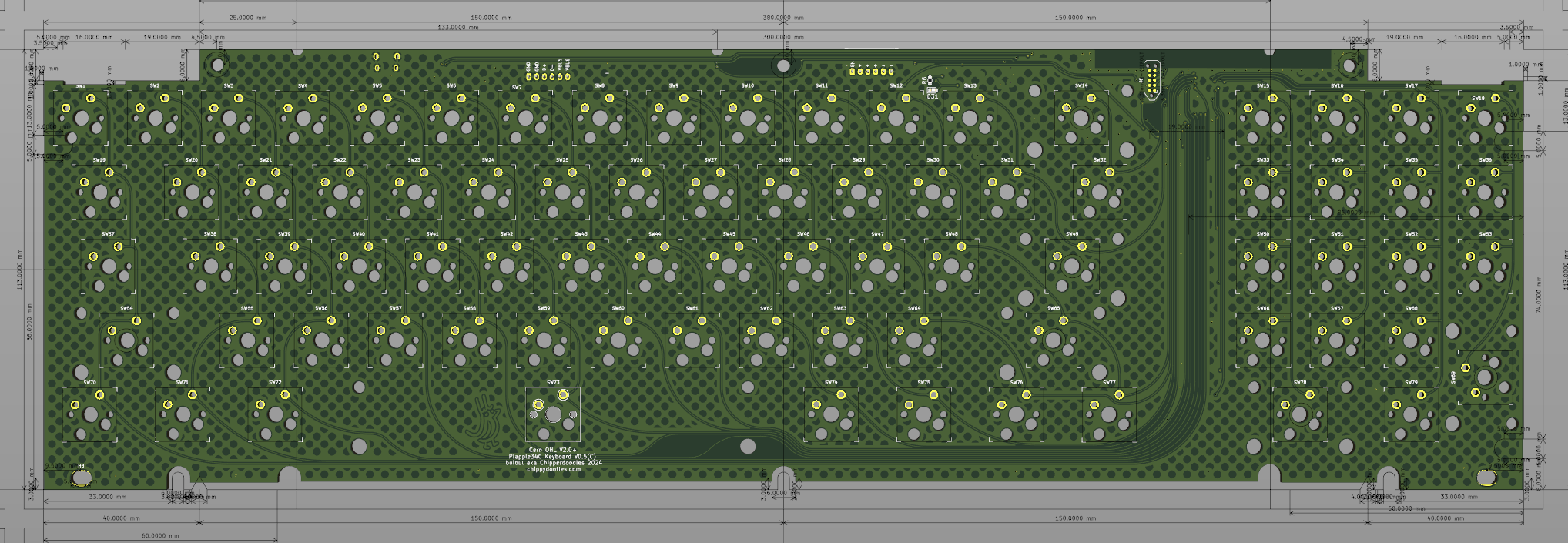
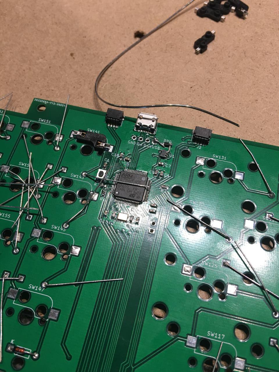
Fast forward a little bit and it was time to take another swing at it, arm support had gotten better with qmk and i figured i should be able to make it work. Revision 2 moved to a more common keyboard pcb design and forgoes the need for the peripheral board. I decided to try out some kailh hot swap sockets, breakout the i2c connections and the MCU chosen was an stm32F405.
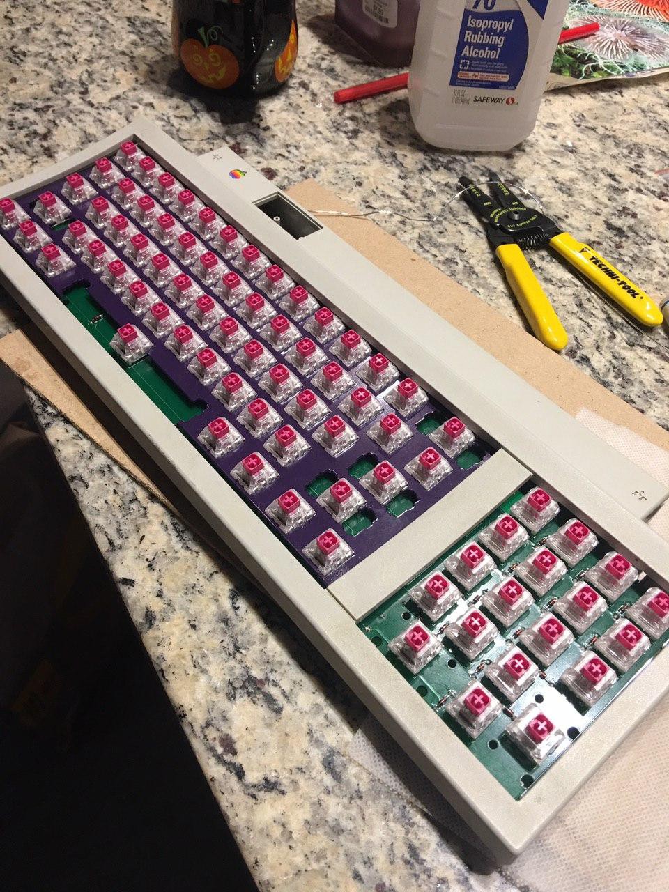
This version had a more accurate fit in the case (not perfect) as well as the ability to be used outside of any case if you wanted to. Programming was done over dfu and the reset button was a bit awkward and as you can see in the above picture i had botched a diode connection which i just bodge wired to the vbus breakout which was luckily the only electrical oopsie. A friend had helped laser cut me an acrylic 60% switch plate which I think I reused a couple times (hence why it looks a little broken in the below picture).
A note is that this design needs 2 separate switch plates, one for the 60% area and one for the numpad, the case bar between the two prevents from using a single custom switchplate. I happily found that generic easy to find 60% switchplates fit the case and design leaving me only need worry about the numpad plate which I could get from a laser cutting service eventually.
Not much else huge in this update, a caveat to the board design is the right most pcb stabilizer holes are cut off and still present in the modern design, I'm worried extending it would prevent a snug fit so I've just dealt with it as is. Most progress was in me futzing around and learning qmk, this was before more boards with relateable mcu's were common in qmk so it was slightly more challenging but still relatively easy to cobble something together.
A note on the cases, I originally just had one apple keyboard II but for the purpose of testing different cases and having some complete keyboards to test I acquired a few more through ebay (purchased ones with known issues/not working so i wouldn't be gutting a good board).
There were 2 manufactures of this keyboard, smk and mitsumi. The cases have small differences and from my very small sample it looks like the smk ones were of a little higher quality.
The internals of both include:
Controller PCB - printed circuit board with controller mcu as well as ADB connectors/reset switch
Metal backing Plate - this is curved, all the keys are same height, it's the physical shape of the board that is stepped
plastic printed circuit sheets - contains the keyboard matrix and connects to the controller board via fpc like connection
plastic molded layer- determines the key layout and holds the barrels as well as locks the printed circuit sheets in place
top and bottom case
My first attempt at building the board i wanted to mimic the separate controller and keyboard matrix, with the idea that you could make the controller modular and reuse the same matrix.
A breakdown of revision 1 as follows:
Separate Controller PCB and Keyboard matrix
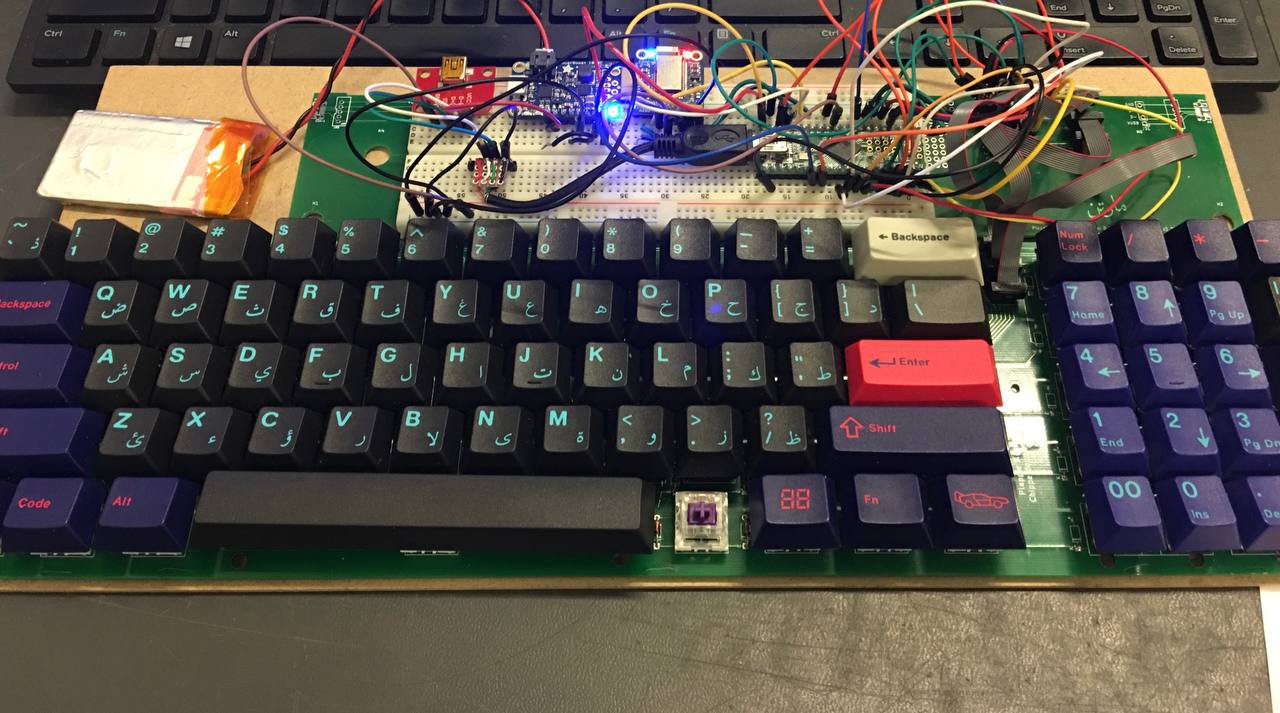
Controller had a teensy ++, adafruit bluefruit, adafruit powerboost, slide switch for power and reused the mini din connectors from the old controller boards
A forbidden cable of USB -> Mini Din connector was made for the external connection then a weird spliced open hand wired mini usb internally. I wanted to reuse the old cable and it's hard to beat that coiled cable fun. It was electrically passing the 4 usb connections just wired to the mini-din
Three separate 2x10 1.27mm pitch cables were used to connect the matrix to the controller board. This ended up not working so great as the heads of the connectors were rather large and prevented the case from closing. I ended up breaking the plastic seperation bar (the one between numpad and rest of the keyboard) of the top case so it could close.
The slide switch was positioned in the approximate area were the reset button would be so you could reach in and toggle battery power
Below you can see revision one pictured:
Breadboard version:
Made a protoboard controller:
assembled:
It was functional! however the case fit wasn't perfect and even after breaking off the plastic the case wore down on those 1.27mm connecting cables. I Should note this proto comes long before my confidence in SMD soldering took place hence using available through hole parts. Theoretically would make it easier to hand solder everything and make an easier diy project but I was on the fence about the practicality of it.
Also to note you can assume that in-between revisions there's a kinda constant tweaking and remeasuring so i could get the case fit better, some compromises were also made when designing controller boards to make them fit in both styles of cases vs one.
I'd consider revision 1 a clunky diy quasi success but it was nowhere near as clean as I wanted it which leads to r.2 which I'll cover in the next backlog
By using our website and services, you expressly agree to the placement of our performance, functionality, and advertising cookies.
Learn More
 Bulbul