-
1Step 1
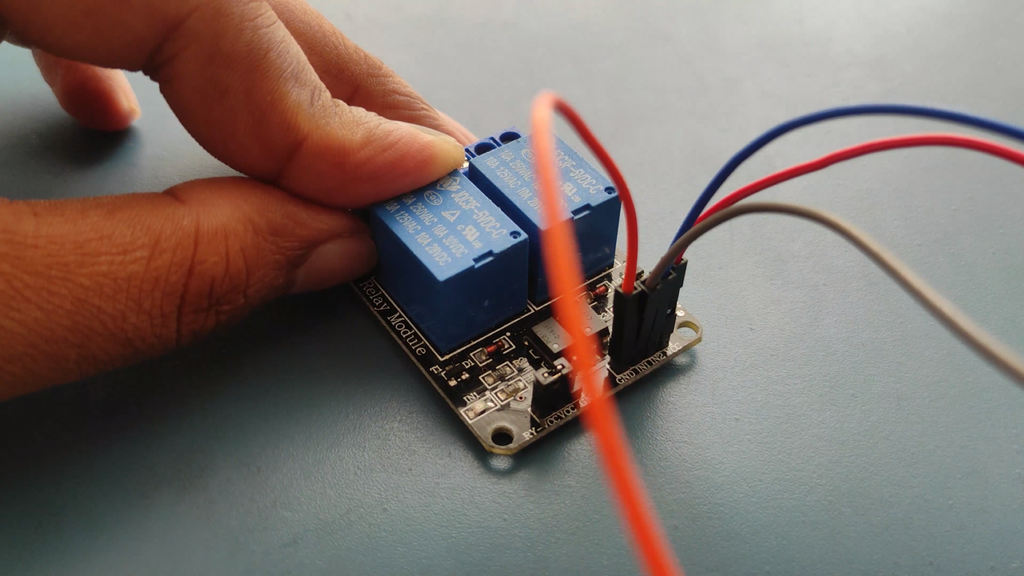
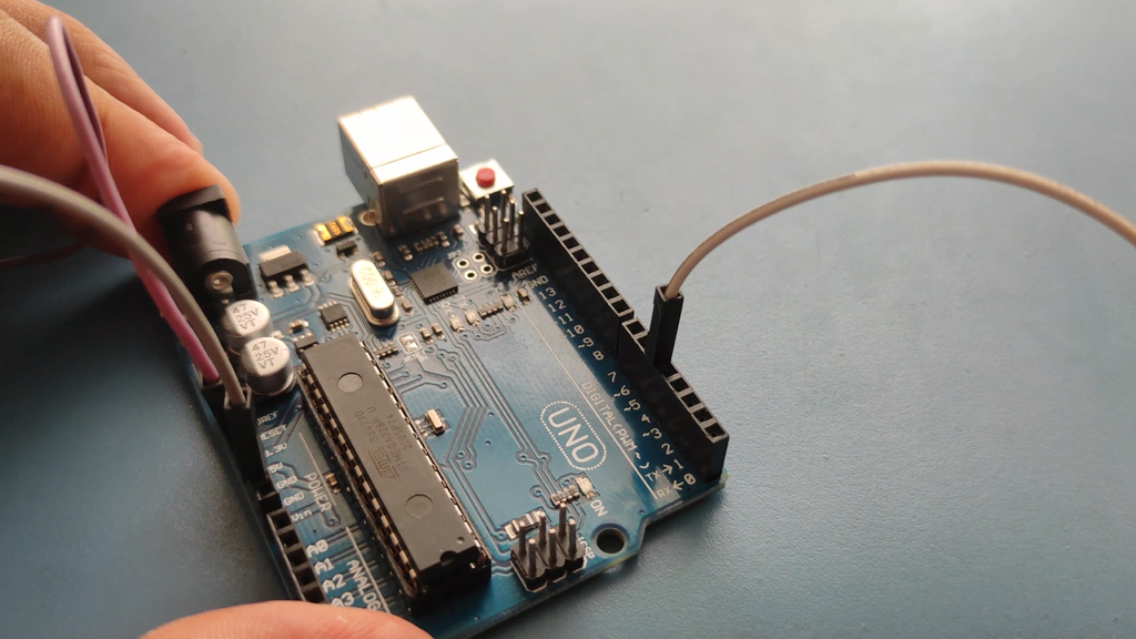
The circuit design of Home Automation based on Arduino and Bluetooth is very simple and is explained below.
The Bluetooth module has 4 – pins: VCC, TX, RX and GND. VCC and GND are connected to 5V and ground from Arduino UNO. The Bluetooth module works on 3.3V and it has an on board 5V to 3.3V regulator.
The TX and RX pins of the Bluetooth module must be connected to RX and TX pins of the Arduino. In Arduino UNO, we are defining pins 2 and 4 as RX and TX using software. Hence, TX of Bluetooth is connected to pin 4 of Arduino.
But when connecting RX of Bluetooth to TX of Arduino (or any microcontroller as a matter of fact), we need to be careful as the pin can tolerate only 3.3V. But the voltage from TX or Arduino will be 5V.
![]()
So, a voltage divider network consisting of 10K and 20K resistors are used to reduce the voltage to 3.3V approximately.
A resistor divider because it divides down the input voltage. We obtain the 3.3V level signal from the intersection of these two resistors.
The equation for a divided down voltage is Vout = [2.2k/(2.2k + 1k)]*5V = (2.2k/3.2k)*5V = 3.46V, which is close enough to 3.3V to prevent any damage to the HC-05.
This crude solution should never be used with a high-speed signal because the resistors form a low-pass RC filter with any parasitic capacitance on the connection.
![]()
As you can see the circuit is very simple and does not need many components to build. Let's start our explanation with the ESP8266-01 Wi-Fi module. You can also check out the video at the bottom of the page for a more detailed project explanation. To program the module, you need to first flash the firmware on the ESP8266 module and you also need to flash the firmware on the PIC12F675 module before doing anything.
Temperature & Light Controlled Home Automation
Here i use ldr sensor & dht11 Sensors to control the light , Fan Also How The Feed In I2C Lcd Display


Discussions
Become a Hackaday.io Member
Create an account to leave a comment. Already have an account? Log In.