-
13D print
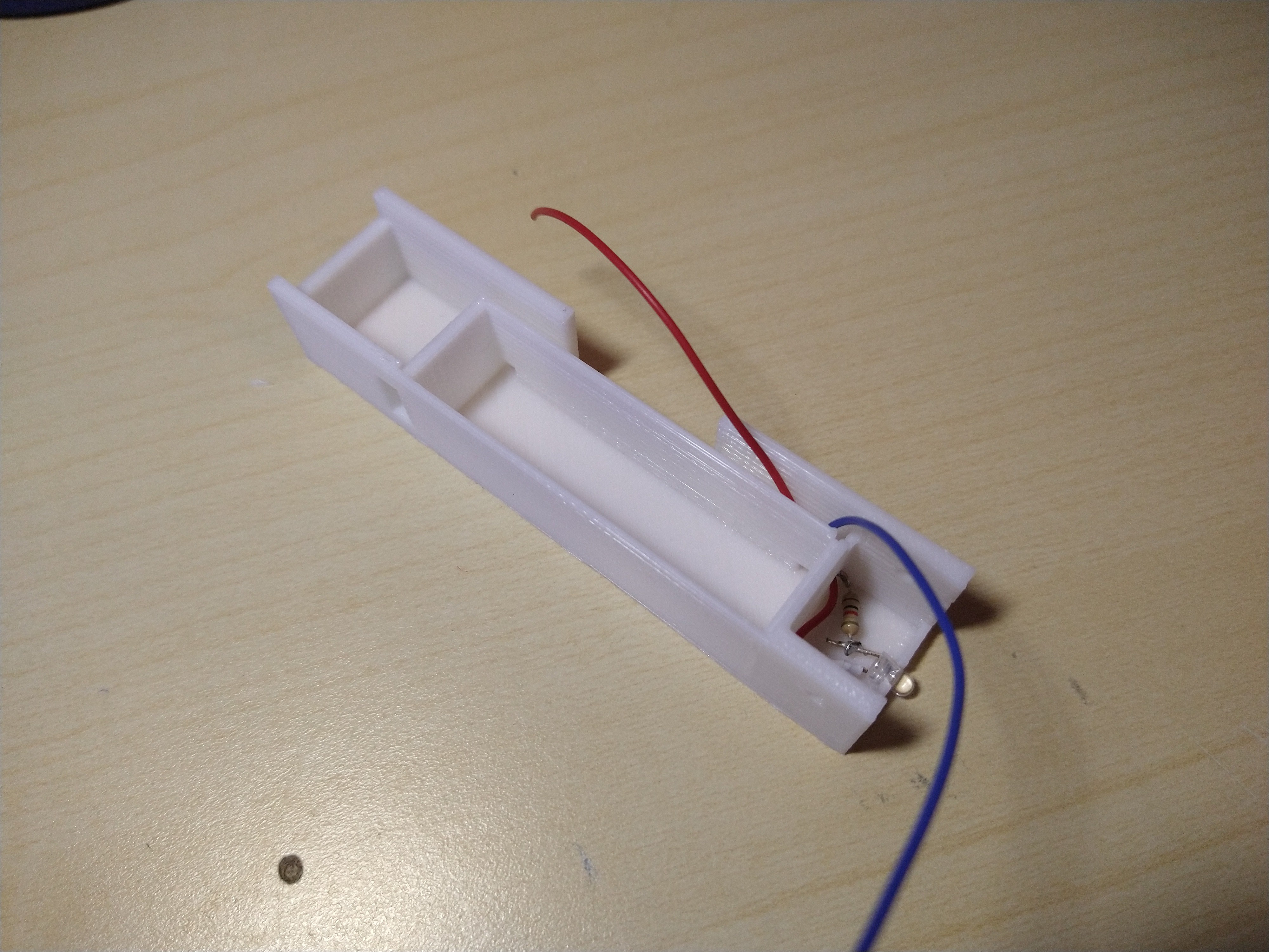
Start by printing the body of the camera system. It is a single piece with the dimensions of 95x22x177mm, capable of holding all the components. I printed it in PLA, but considering the heat developed by both camera and VTX, ABS is strongly recommended. In the meantime, begin to solder the LED to the resistor and the microswitch.
-
2LED
Once the print is completed, begin by placing the LED assembly in the correct location. Both the LED and the switch need to be secured in place with some glue. Apply a piece of tape over the LED to avoid short-circuits with the camera.
![]()
-
3Power system
Solder the cables to the battery spring and the clip, then force the cables through the two small holes in the sides of the battery compartment. Connect the cables to the DC-DC booster (Vin+/Vin-) and prepare the cables for the output too.
![]()
-
4Electronics
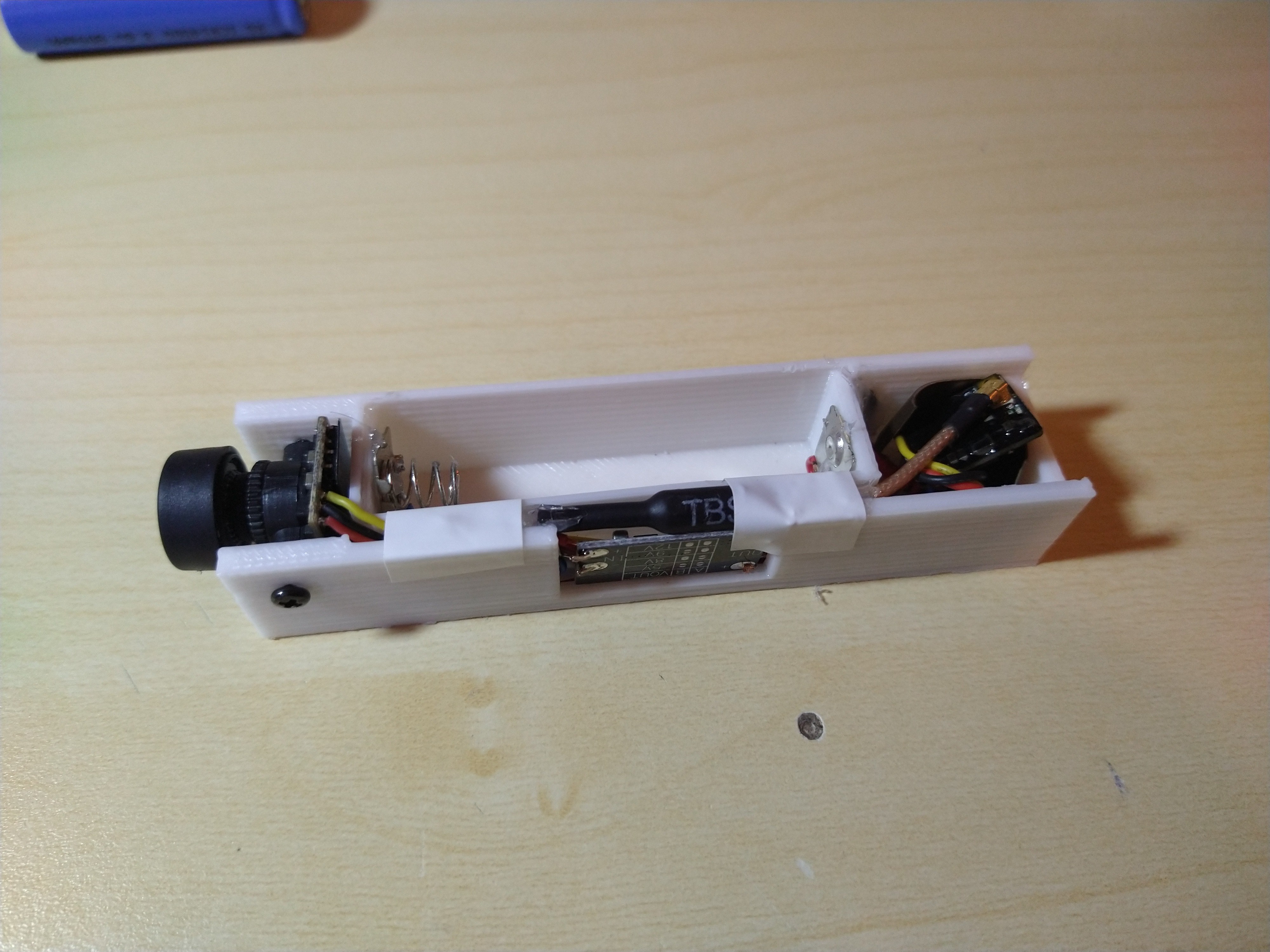
Place the camera in the front of the assembly and secure it in place with a couple of M2 screws. Run the cables in the apposite tray and connect the video signal (yellow) to the VTX.
Fix the DC-DC booster in place (the window on the side) and connect all the positive and negative cables.
Use hot glue to place the battery holders, the booster and to secure the antenna in a safe position. That won't keep it in place when the unit is running hot, so use a bit of tape too. Try to avoid direct contact between the housing and the VTX. I placed a piace of heat-shrink in between.
![]()
![]()
-
5Test
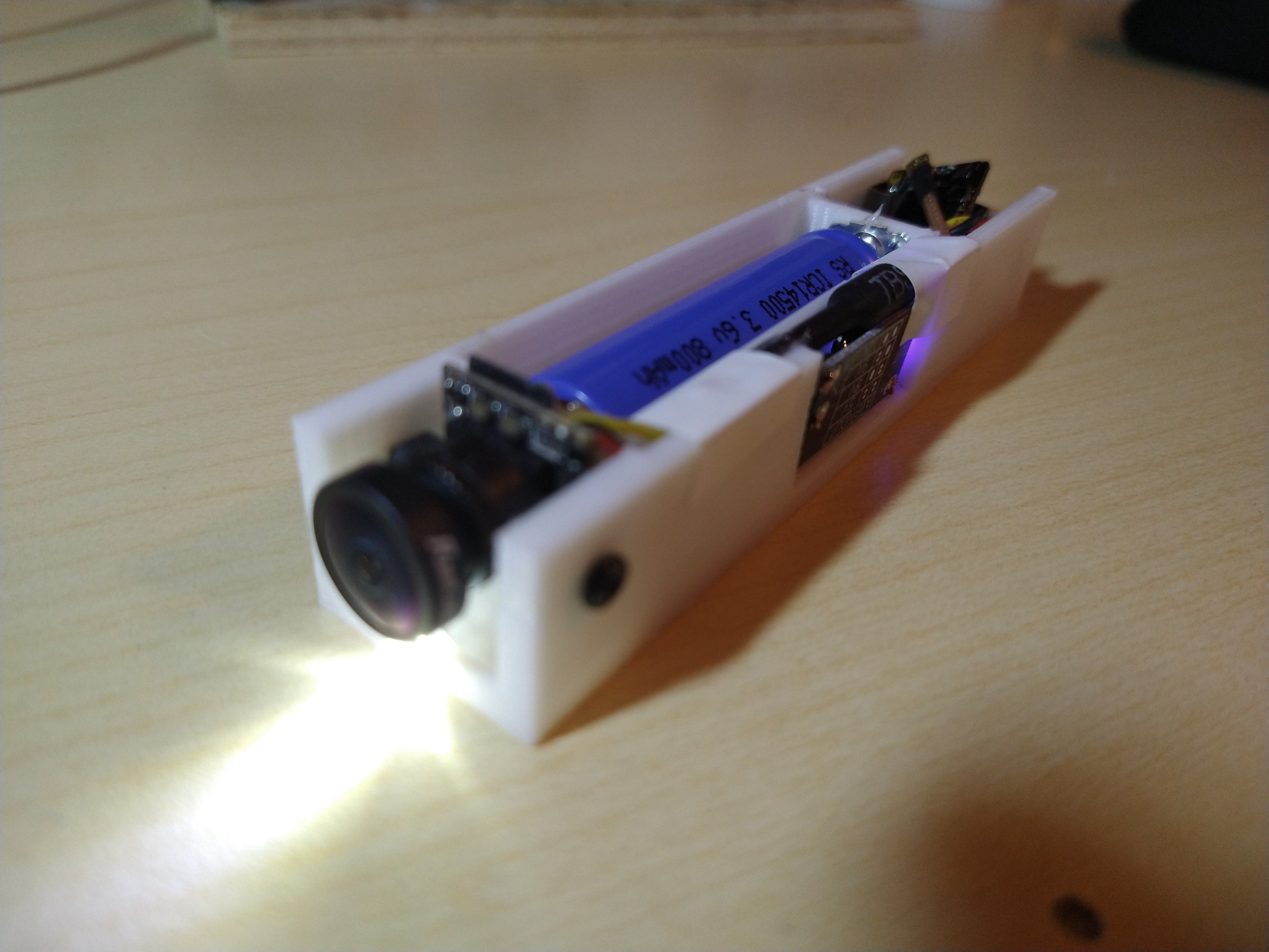
Smoke-test everything with a bench supply (current consumption is around 700mA) and if everything works place the battery.
![]()
 Vassily98


Discussions
Become a Hackaday.io Member
Create an account to leave a comment. Already have an account? Log In.
Why didn't you use track power?
Are you sure? yes | no