Close
0%
0%

DIY Mech/Exoskeleton suit.

Mechs are not viable, nor cheap, so I will try to design and build one alone anyway.

Similar projects worth following
Mechs are cool and I wasted a not trivial amount of time researching about related topics that I think are equally as cool and interesting.

I hope I can build one or more mechs, but first I need to actually project one.

I will try to list in this project here all the ideas I had/have because I'm noticing that I'm repeating the same cycle of ideas, and by putting these ideas on paper, I will finally just forget this mech thing and move on to better ways of using my time and effort, or just be completely consumed by it.

I'm not an engineer, neither a programmer, SO DON'T RISK YOUR LIFE DOING THIS PROJECT! **You can die.** **You've been warned.**

Everything I use and/or make is open-source.

Also², the Artist of the pic/painting of this project is "Ukitakumuki Kai Lim", you can find their profile on Devianart, the specific pic is called: "Project Boots: PANAM Armour". I linked them in the external links.

Everything in this project can kill you.


I'm not an engineer, I'm not a programmer nor do I have any kind of useful expertise.

You shouldn't be doing this DIY project without professional help.


You can die. You've been warned.


---------------------------------------------------------------------------------------------------------------------------------------------


This is a guide, not a instruction's book.

Well, the idea of this project is to be more of a guide-book rather than a rule-book, I will make my own stuff, but it doesn't mean you can't learn other things that could be useful for your specific needs.

Plus, I'm not even an engineer, a professional would have finished this project a long time ago.

The project logs are long and counting up, my apologies for that, but if you want to really just start where the project truly starts, go to Project Log 54 forward.

Previous project logs are more or less about exploring every option that I could find and learning all the necessary stuff for the project rather than an actual manual.

That's why I think it could be relevant for you to read everything first if you aren't familiar with engineering in general, or if you just want to understand why I abandoned certain ideas and kept working with other.
During the project, I changed my mind a myriad of different times about how to build this thing, and in hindsight, I think it was for the best.

So I think it is worth making the choice of studying every option before actually committing to build it. I saved so much money that I would otherwise have expended for dead ends that I didn't knew it were dead ends.

Right now I'm writing Project Log 68, so I'm more or less on the "final steps" before actually building the thing itself.

Again, this is not a "connect part 2B with part 3A in this way", this is more of a "I connected part 1, 2 and 3 this way because I think it would be stronger and easier to build, if there is a better way, I don't know, but I heard that you could connect these parts in a X configuration, which I never tested before" kind of DIY guide.


Index:

Bearing.zip

DIY Slew Bearing for Exoskeleton as stated on Project Log 69: https://hackaday.io/project/188391-diy-mechexoskeleton-suit/log/222406-project-log-69-diy-endoskeleton-and-exoskeleton It is a blender archive compressed in a zip archive, which I should have done sooner.

x-zip-compressed - 39.45 MB - 09/20/2023 at 21:07

Download

Electric motor.zip

3D models of the DIY electric motors mentioned on Project Log 58: https://hackaday.io/project/188391-diy-mechexoskeleton-suit/log/220958-project-log-58-diy-electric-motor

x-zip-compressed - 23.72 MB - 09/11/2023 at 17:20

Download

DIY Hydraulic Pump - 1, 2 & 3.zip

Mold for stator, gearbox, "motorbox" and hydraulic pump as stated in Project Log 68: https://hackaday.io/project/188391-diy-mechexoskeleton-suit/log/222346-project-log-68-diy-hydraulic-pump (Hackaday limits singular archives to be uploaded to 50mb, so I compressed to this one here)

x-zip-compressed - 36.26 MB - 09/11/2023 at 17:17

Download

  • Project Log 89: Screw it, let's freaking do it.⁹
    FulanoDetail09/07/2024 at 23:51 0 comments

    The project log 87 got so long that I had to split it into project log 88 and 89, sorry for that, lol.


    Manufacturing The Mech parts:

    I still need to make the 3D model, calculate weight and all that stuff, but I just want to get this out of the way first.

    Obviously, I will run into more details when I actually start building, linking all the proper tutorials that I followed, precise steps that I took and the like (yes, on the details I say this is more of a guide, but being frank, this way I will be forced to actually organize my stuff, lol).


    For the Coils of stator, bearings and couplings:

    1. Find a soda can for aluminum scrap.
    2. Triturate all of it, take out the paint, clean it up as much as possible.
    3. Take the proper weight of aluminum welding rods 4043 and 2024, fluxes etc.
    4. Make the microwave kiln with sodium silicate and silicon carbide.
    5. Use the same materials to make an aluminum wire extruder (first I thought of doing that idea of pouring paraffin wax in sand for a wire mold, but that would take too long. 
    6. Purify the aluminum scrap as much as possible, taking out dirt, humidity and the like (I don’t want an aluminum steam explosion in my face).
    7. Buy all the safety equipment for forging aluminum (I want to DIY everything, but molten metal is risky).
    8. Make a pile of dirt sacks around the kiln and the extruder for extra safety.
    9. Heat both the kiln and the extruder so there isn’t a thermal shock explosion.
    10. Make the process of manufacturing aluminum wire at a safe distance.
    11. Then use a cheap Carbide Wire DrawPlate to smooth out any imperfections on the surface.
    12. Anodize the aluminum wire for insulation, just like enameled wire, it will serve for protection and avoid short-circuits.
    13. Make the aluminum coils into the desired shapes using 3D printed molds and the like.
    14. Heat treats the aluminum coils in an artificial aging process for hours or days.
    15. Infuse the coils with a mixture of polymer (such as HDPE) composite with thermal paste for heat dissipation (DIY or not) and a thermochromic paint (DIY or not if possible) in order to make the visualization of heat easier.
    16. You can add a ferrite polymer composite core or not to the center of these coils for a slightly better magnet field.
    17. Position the wired coils into the stator’s molds, connect them with the 3 phase correctly (check and recheck multiple times, any mistakes will be hard to correct) and inject the mold with structural polymer for stator completion.
    18. Then I would use good insulating materials around the motor housing to avoid frost build up.
    19. That also applies to bearings, couplings, servos etc.

    I was thinking of making the mold using glass panels, they are made with incredible tolerances (in the micrometer range) and thus, the rotors would also have those tolerances if made with the same surface.

    The space between the coils, magnets and the like would be dependent on the precision of the mold, which on another hand, would be limited by the method of fabrication.

    I was thinking of using resin 3D printing (in this case, hire a 3D printing business for this specific case).

    But in hindsight, I feel that it would be unnecessarily troublesome, I could do it with laser printed plastic schematics with measurements glued to a glass and align the parts with it.

    I was even thinking of using an DIY light/shadow projector, the bigger the projected shadow/light, the higher the precision. But you would need a lot of space for that.


    For the permanent magnet rotors:

    1. Find and/or buy Alnico/Neodymium magnet powder or turn Alnico/Neodymium magnets into powder. Do that in some oil because neodymium is highly reactive with oxygen.
    2. Mix it with a 95% magnet powder to 5% polymer composite, just like the coils, the polymer, thermal paste and thermochromic paint. Some magnets can survive from up to hundreds of degrees celsius, but not the plastic.
    3. Do that under a strong magnetic field, so the particles will align properly during injection and curing.
    4. Use a magnetizer to turn these magnets into permanent magnets....
    Read more »

  • Project Log 88: Screw it, let's freaking do it.⁸

    FulanoDetail09/07/2024 at 23:41 0 comments

    The previous project log got so full I had to split it up to this one.


    I added more information to the bot:

    To determine whether the characteristics of a brushless motor with a specific magnetic flux density are considered good or bad, you can evaluate several factors that influence motor performance. Here's how you can approach this:
    Magnetic Flux Density Values: For brushless motors, the magnetic flux density (B) typically ranges from 1 to 1.7 teslas (T) for efficient designs. Your calculation of 1 to 2.5 T for an 80 kW motor at 4000 RPM and 300 Nm of torque indicates that you might be targeting higher performance levels. However, while NdFeB magnets can achieve values above 1.0 T, exceeding the recommended limits can lead to issues such as irreversible demagnetization, especially under high thermal stress or external demagnetizing fields [1][5].
    Torque and Current Relationships: The torque produced by the motor is directly related to the magnetic fields in the air gap, which are influenced by the current flowing through the windings. When designing your motor, you should consider the maximum current that your motor can handle without overheating. For instance, typical current densities for brushless motors can be around 16 A/mm² [1]. If your design requires higher current densities, it may affect the thermal management of the motor and ultimately its performance.
    Torque Ripple and Performance Consistency: Low torque ripple is desirable in brushless motors. A torque ripple of about 2% is considered very low and indicates a smooth operation of the motor [4]. You should aim for designs that minimize fluctuations in torque to improve overall performance.
    Thermal Considerations: The performance of magnets, particularly the residual flux density and coercivity, is temperature-dependent. The temperature coefficients for NdFeB magnets indicate that the residual flux density can decrease by approximately 0.10% per °C [6]. Therefore, it is critical to account for the operating temperature range of your motor to ensure that it can maintain performance without demagnetizing.
    Design Innovations: Consider innovative rotor designs that can help minimize leakage flux and maximize torque density. Structures like flux barriers can help concentrate the magnetic flux and reduce unwanted leakage, thus enhancing the overall output power density [5].
    The maximum magnetic flux for neodymium magnets, particularly the NdFeB (neodymium-iron-boron) type, is a critical factor in the design and performance of brushless motors. The residual flux density (Br) for these magnets is typically around 1.12 T (teslas) at room temperature (20 °C) [1].
    Flux barriers in the stator yoke of an electric machine are typically made from non-magnetic materials or air gaps. The primary purpose of these barriers is to increase the magnetic resistance (reluctance) in specific areas, thereby controlling the magnetic flux path and reducing unwanted harmonics.
    Here are some common materials and methods used to create flux barriers:
    Air Gaps: Simple air gaps are often used as flux barriers. By cutting specific shapes or slots into the stator yoke, designers can create regions where magnetic flux is impeded or redirected.
    Non-Magnetic Materials: Materials such as plastics, ceramics, or composites with low magnetic permeability can be inserted into the stator yoke to serve as flux barriers. These materials do not conduct magnetic flux, effectively creating a high reluctance path.
    Non-Magnetic Metals: In some cases, non-magnetic metals like stainless steel or aluminum may be used. These materials are structurally strong but have low magnetic permeability, making them suitable for certain designs.
    The choice of material depends on factors such as the specific application, cost, structural requirements, and the desired magnetic properties.

    So, magnetic flux around 1 tesla on each slot, the flux barriers are already...

    Read more »

  • Project Log 87: Screw it, let's freaking do it.⁷

    FulanoDetail09/07/2024 at 23:27 0 comments

    Friday, 16/08/2024, 16:19

    I feel like my passion for this project is just fading away. I liked spending time researching and theorizing and all that stuff, but I feel like I never make any progress.


    I mean… I don’t know. Pretty funny how I’m feeling down so close. And even funnier how everything seems so close and so distant at same time.


    I talk, I talk and talk, but I really don’t know what to do…


    I feel like I don’t know what to do, I feel totally lost


    I’m really undecided on what to do next? Or am I just trying to procrastinate?


    You know what? I just promised to myself I will only post this project log when I actually finish 3D modeling something.


    It is funny to me that every day I’m either “this project is stupid, I’m a joke” or “f*ck yeah, this project is awesome”


    Also, have you guys seen the teaser for “Secret Level”? There will be a f*cking animation from Armored Core!


    It seems that this project log is so long it won’t fit in a single post, sorry for that.

    The one time I actually do something in this project and the posts are completely overwhelmed.


    Also, for some reason I decided to make a wargame tabletop with a friend of mine. I’m definitely not good with my life choices… Because it will also take years to just study the already existing wargames systems and rules.


    About Electromechanical Rheostat Servos:

    In the previous project log I talked about how the electrical actuator mech with electromechanical rheostat-switches wouldn’t be practical because I would need a lot of brushless motors.

    Obviously I was wrong, although I don’t have the precision to make tiny brushless motors on mass, I can actually make something closer.

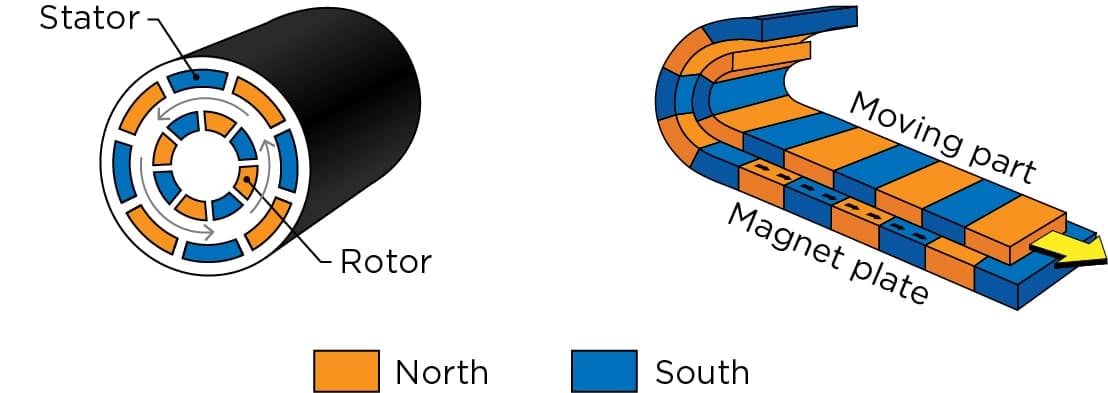
    1. I can make linear brushless motors that can rotate crankshafts.
    2. I can make solenoid that also can rotate crankshafts.
    3. I can make bigger, less efficient DIY brushless motors.

    For some reason the obvious never crosses my mind on the first try.

    I will list here some videos I found about making DIY brushless motors, there are many, so I will just put the links:

    Anyway, I need to start 3D modeling this piece of crap that I call mech, and then I will need to actually build something.

    And my first doubt is: how should I make the direct drive brushless motors for the mech?

    I mean, I’m thinking of just going “frick it, we ball” and 3D modeling every option of actuator for the mech. The linear brushed motor, the linear brushless motor and then the rotary brushless motor.

    … And maybe the exoskeleton I talked about before.


    High Torque Density motor:

    Before I finally go with the hydraulic/hydrostatic route, let me at least try to find a super high torque to weight ratio actuator. Maybe this way I can still keep it fully electric.


    Being honest, I doubt I will be able to pull it off, but even if I reach a pretty close value to those ultra light high power motors, it is still going to make the electro-hydraulic mech lighter.


    Anyway, what number of poles and slots would I need for a direct drive brushless  torque motor?

    I always use the REB-90 as the reference and I also posted that excel document on which shows the best ratio of slots and poles, but none of them talks about the number of slots/poles based on the power output you want.

    The “best” approach I have for now is to “just” increase the AWG of the wires, since changing the wires of a brushless motor for a thicker one also increases its torque while decreasing its output speed.

    I already 3D modeled the REB-90 copy ages ago, so maybe I just need to cut the number...

    Read more »

  • Project Log 86: Screw it, let's freaking do it.⁶

    FulanoDetail08/08/2024 at 22:40 2 comments

    Monday, 05/08/2024, 14:19

    Well, it seems like I talked too much useless stuff in the previous project log, because it ran out of space for new text to be added to it.

    1. First: find a relatively good alternator’s diagram in order to copy it.
    2. Second: list every part of it and the resistivity, inductance, etc. of each part and find a good enough DIY substitute.
    3. Third: actually build it for once?

    Maybe make the 3D model of the parts?


    Well, I didn’t do sh1t and just procrastinated, so I will just post this thing incomplete.

    Maybe this way I will take some shame in my face and actually work on this project (brazilian expression).


    I'm still procrastinating, but I asked ChatGPT how to make a 700ºC inverter and he just said it would be impossible. 💀

    "I'm afraid it's not feasible to create a 1 kilowatt inverter that operates at 700 °C from scratch, as the temperatures you're mentioning are far beyond the capabilities of typical electronic components and materials. Even advanced ceramic semiconductors used in high-temperature applications usually have a maximum operating temperature of around 200-300 °C."

    The only reason I wanted to make an DC to AC inverter would be to wireless transfer power to the rest of the mech without need to cool the power cable down and maintain as high efficiency as possible. If I can't make the goddang inverter to survive 700ºC, then what is the point?


    The only way I thought of making it work would be using a mechanical switch, a literal electric motor connected to a disk/lever that would mechanically change the flow of electricity.

    I could only think of electromagnetic coupling.

    And finally, I need to build it up in order to see what is the energy output of the Molten Fuel Cell in order to convert it to the appropriate voltage/amperage.
    But alas, I could do it with the induction coil, so it acts both as a wireless power transfer and as a transformer.

    Wouldn't that mean that I could make the 3-phase brushless linear motor for the actuators without a ESC controller, but just a mechanical switch controlled by a smaller electric motor?

    huh... 😐


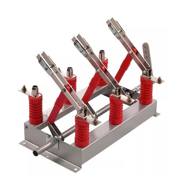
    This is a 400 amps 15,000 volts switch, by the way:

    This one costs 2000 reais (360 dollars), btw.


    I just remembered about rheostats/potentiometers.

    A potentiometer just changes the resistance for signal transmission control, a rheostat changes the resistance of the conduction of power.

    This is a rheostat for power transmission:

    This one is for a 3 phase 10 kilowatt rheostat:


    I feel like this is so stupid...

    Should I stay with the MHDG?


    About the Inductive Magnetohydrodynamic Generator (IMHDG):

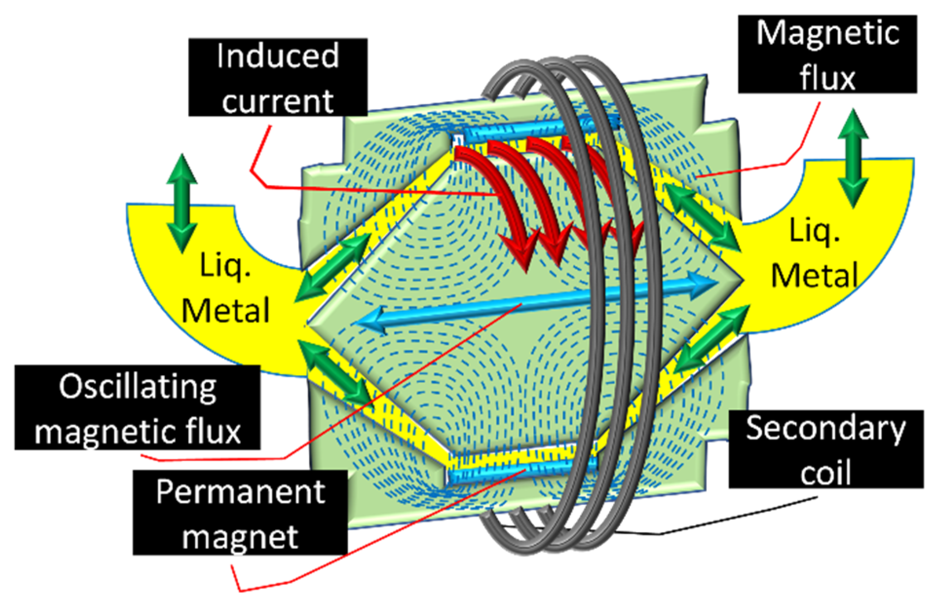
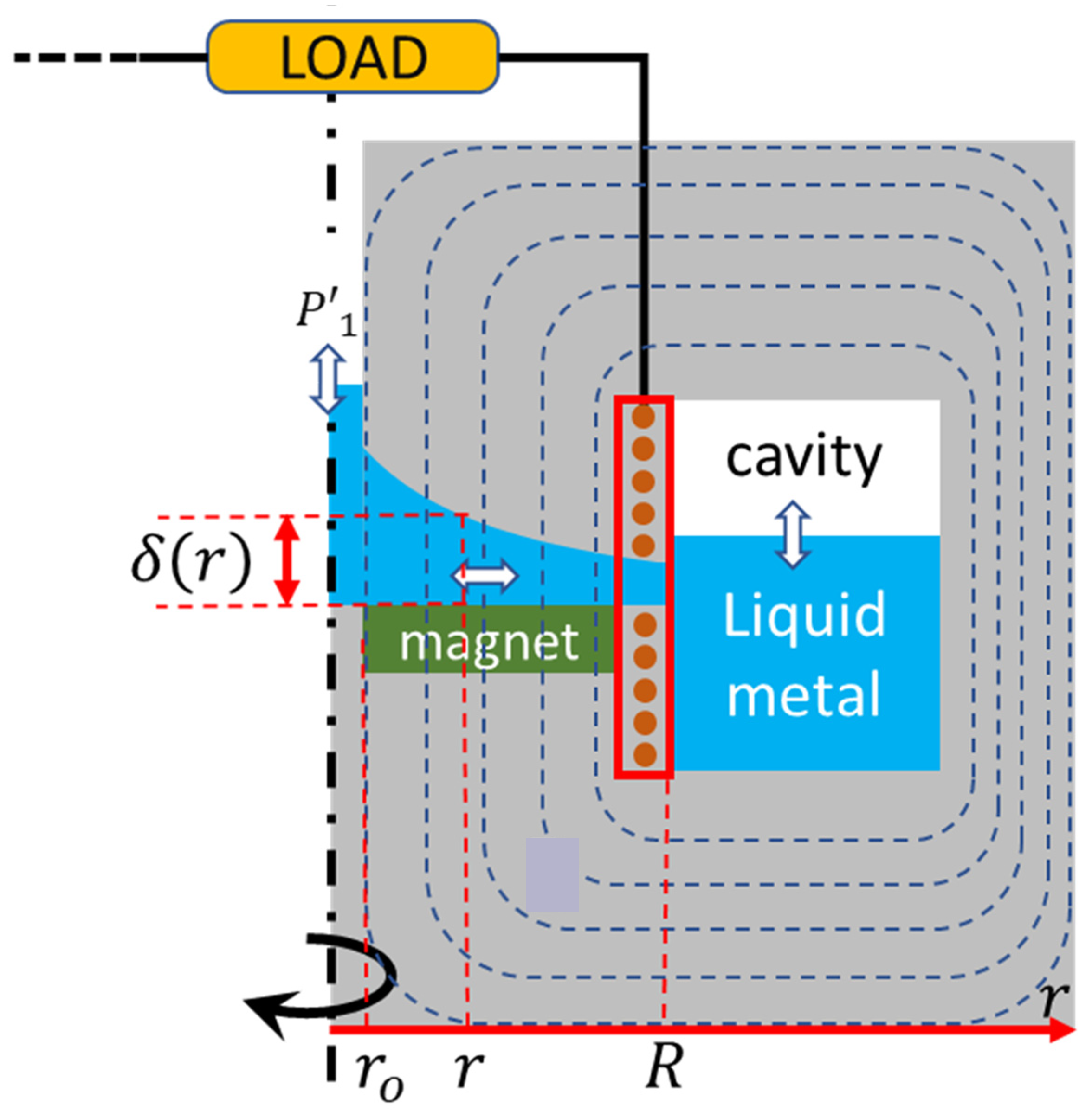
    I was wondering how would be another way of making this generator efficient and compact with a somewhat certainty that it would actually work, the only thing that I could find that is similar to what I’m thinking of was to mix a liquid metal MHDG with an ejector in order to make it work without the problem of electrodes simply melting.

    The idea would be to mix a vacuum ejector:

    With this thing here:

    Source: https://www.mdpi.com/2071-1050/13/23/13498

    It is a molten metal MHDG for a radioisotope power source for a satellite, according to the simulation/calculations in the paper, it is said that the higher the temperature and intensity, the higher the efficiency. Achieving a maximum 50% efficiency.
    This is the same author that made this article about a liquid metal disk MHDG:

    Source: https://www.mdpi.com/2071-1050/15/16/12619

    And according to him, the efficiency can reach around 70%.

    Now it is the part that I talk about the problems:

    First off, I already talked about a similar design, but for a combustion driven water turbine because a conventional combustion turbine would require really expensive materials.
    And this idea is essentially that, but with liquid metal and a less efficient way of converting kinetic...

    Read more »

  • Project Log 85: Screw it, let's freaking do it.⁵

    FulanoDetail07/30/2024 at 14:09 2 comments

    Tuesday, 09/07/2024, 16:11

    I’m writing this here on google docs first.


    Well, soon or later I would need to figure out how to make a PCB for controlling the mech.

    I kept avoiding it because I really don’t know how I would wrap my head around these concepts. In fact, I already tried multiple times to learn how to make the control board, but with no success…

    Depending on the result of this “serious” attempt may or may not result in the possibility of a brushless linear actuator instead of a sliding contact one like I was babbling about in the previous project log. After all, both the ESC and the energy supply would do basically the same thing, changing the voltage, amperage, frequency and which actuators receive it.

    Also, I don’t know if all this work I had making a rough estimation of the coils strength would actually be useful, since, you know, the energy would be divided by all actuators and rarely a single one would actually use all the 200,000 watts of power.

    And I also doubt the system would even survive such energy input… Maybe I’m really over-engineering this thing with all these 40 ton cylinders.

    … Bruh, 9 days in and I still didn’t even start to research this subject. I’m procrastinating too much…

    Bruh² my drawing table with a display from Huion stopped working out of nowhere. 😐

    Luckily I’m still within the time duration for a refund.

    Now I don’t know what to do… Do I try to buy another table from a different seller or just… Keep going with this project…?

    I bought a used one for ⅓ of the price, lol.

    … I've been procrastinating for so long, and this project has already taken so uselessly long that I’m wondering if I should hire someone to design this garbage can for me.

    Oh yeah, I tried it before, they asked for AT LEAST 30,000 reais (5400 dollars).


    ACTUAL WORK:

    Goddang it, I hate how I procrastinate so much, but I think I can trick my mind into properly working right now.

    Basically, I was literally saving a bunch of videos explaining the literal basics to advanced concepts involved in electronic systems, so it was a daunting task for me from the beginning. SO, my “brilliant” idea was to actually take already existing units of what I need and find a DIY material that can survive the insane temperatures I need it to withstand.

    For example, the first system I was thinking of studying/designing/building is the DC to AC inverter for the molten fuel cell.

    The molten fuel cell will be at around 400ºC to 650ºC, so I can’t just buy a commercial inverter. However, I could copy the system schematic of a commercial one and replace the materials with high melting point ones.


    On top of that I can only predict so much without actually building anything, and that applies to the molten fuel cell.

    For example, this article states that its 10 kilowatt fuel cell produced 56 volts without stating its amperage, but doing the math, you can find that it is 178.5 amps. But it uses cells in a well produced cell, not this amalgamation of inconel and stainless steel that I intend on making.

    And I NEED to make the cell this way, because if I’ve made it the traditional way, it would be the size of a truck.

    … Now that I think about it… In a molten carbonate fuel cell, how the amount of electrolyte is determined by the amount of energy I need for it to output? What is the calculation for this?

    WebGPT keeps saying out of its butt that the Molten Carbonate Fuel Cell needs around 0.1 to 1 liters of electrolyte per kilowatt, but never gives a source for that.

    So, 300 liters of electrolyte = 660 kilograms, 0.1 x 30 = 30 liters = 66kg.

    Of course, ASSUMING it is correct, which probably isn’t.

    In other GPT’s available on the same website they tend to say that the higher the temperature, the less electrolyte is required. But I don’t know how true is that, since the truck-sized 250 kw molten fuel cell is also at 650ºC

    However, in all articles...

    Read more »

  • Project Log 84: Screw it, let's freaking do it.⁴

    FulanoDetail06/21/2024 at 16:43 6 comments

    Tuesday, 18/06/2024, 19:06

    Well, I’m writing this in a google docs first and then later posting on hackaday.io because it is having a lot of trouble staying up.


    Power Source:

    So I will write what is in my mind right now:

    So, I’m kinda pissed off because it seems like the molten carbonate fuel cells and molten hydroxide fuel cells kinda fricking suck and are equally dangerous. Plus, I don’t really need lithium carbonate in a lot of quantities because it is more of a catalyser for the carbonate solution. Most of the articles that I could find on the subject said that they used a nickel anode and a cathode with a layer of lithium while only using potassium carbonate and sodium carbonate.

    On top of that, one of the recurring problems is that the molten carbonate fuel cell also needs the CO2 from the exhaust of its own reaction to be mixed back for whatever reason. And it also can suffer from layer separation, since the carbonates have different densities (akin to what happens to water and oil).

    And well, I also revisited the idea of using magnetohydrodynamic generators, but I’m really not confident on its resulting performance and on its viability while building it homemade.

    The idea is simple:

    1. First, using the plasma jet engine to power a tip-jet rotor.
    2. The tip-jet rotor will rotate an axial compressor.
    3. The air from the air compressor will go to a plasma jet rocket engine.
    4. On top of the plasma, a fuel (gaseous, liquid or powder) will be introduced, increasing the performance of the plasma jet rocket engine.
    5. On the combustion chamber and nozzle there will be a Magnetohydrodynamic generator coil that will turn the flow of air and combustion into electricity.
    6. The electricity will be used to maintain the reaction going just like in a conventional jet engine and the excess used to power the other systems.
    7. This will be an Air-Breathing Plasma Jet Magnetohydrodynamic Rocket Engine Generator (ABPJMREG). 
    • The plasmatron turns hydrocarbons into hydrogen and CO/CO2, so MAYBE the plasma can end up doing something similar on either making more complex reactions and/or more toxic byproducts.
    • Another problem is the amount of noise, heat, vibration, fumes etc.

    Obviously there will be a LOT of variables and a LOT of thought on the type of material required to make this beast to work continuously, and on top of that, dealing with this kind of machine can easily cause my own death.

    Source: https://www.researchgate.net/publication/343747256_Electrical_properties_of_gadolinia-doped_ceria_for_electrodes_for_magnetohydrodynamic_energy_systems?_tp=eyJjb250ZXh0Ijp7ImZpcnN0UGFnZSI6Il9kaXJlY3QiLCJwYWdlIjoiX2RpcmVjdCJ9fQ

    And although ChatGPT (that f*cking stupid chat bot) keeps saying the efficiency of the MHD systems is “90%” the own sources it shows to me prove otherwise, this article (which gpt itself sent to me as the said source) said the magnetohydrodynamic generator on the rocket engine achieved a maximum of:

    “There are energy losses in the MHD channel. These include friction with the wall, heat transfer, electrical resistance of the gas, and electrical losses at the ends of the channel and the conductor walls (17:331). These losses give linear MHD channels using gases at 2000-3000K only a 15% efficiency (35:31).“

    The pancake type is more efficient, but it is said to be 30% efficient. I don’t see the appeal of working my butt off on a glorified plasma furnace that will blow up in my face, melting years of work and thousands of moneys into a giant pile of molten slag.

    Source: https://en.wikipedia.org/wiki/Magnetohydrodynamic_generator

    Source: https://www.researchgate.net/publication/358260240_Existence_of_an_optimized_stellarator_with_simple_coils?_tp=eyJjb250ZXh0Ijp7ImZpcnN0UGFnZSI6Il9kaXJlY3QiLCJwYWdlIjoiX2RpcmVjdCJ9fQ

    This image is from a supposedly “optimized Stellarator fusion reactor”, only god can tell me if any fusion reactor structure would be practical/useful...

    Read more »

  • Project Log 83: Screw it, let's freaking do it.³

    FulanoDetail06/10/2024 at 12:56 2 comments

    Monday, 10/06/2024, 09:44

    (is Hackaday.io going down to all of you or just me? Some times I need to wait an entire day for the website to be accessible)


    Well, I feel like it is a bit too soon to be worrying about design, and specially since I literally didn't start working on it at all even though I name the project logs exactly to do that. :|

    But here we go again with my shenanigans...


    Design of the Artificial muscles:

    Materials for dielectric elastomers:

    Well, since I'm intending on making dielectric elastomer fibers with 1mm of thickness, I can't really just make it whatever way I want and leave at it.

    I could simply connect a single fiber and be done, since very high voltages and very low amperages can travel kilometers in materials without any loss, but if any fiber is damaged, well, you could have the entire thing stop working. Of course, I still could make the fibers slightly bigger and just connect new muscles whenever some fiber is damaged, and I do intend on doing that if this idea shows itself to not be viable.

    (I want to make it as small as possible because I'm afraid that the contraction ratio of the muscle will force me to change the proportions, right now the idea is that the muscle is attached to 1/3 of the limbs length, if I'm reguired to increase it, then it would make the muscles even heavier)

    I need polymers that are soluale in a material, but not in other. At least for the outside layer.

    Polyvinyl alcohol is soluable in water and alcohol, but not in acetone or gasoline.

    Polystyrene (styrofoam) is soluable in acetone and gasoline, but not in alcohol or water. (Funnily enough, polystyrene is even cheaper than PVA)

    Poly(methyl methacrylate) (PMMA) is soluable in acetone, but not in alcohol, water or gasoline.

    Polyvinyl chloride (PVC) is soluable in acetone, but not in alcohol, water or gasoline.

    So, if my brain isn't being stupid: for half of the outer layer of PVC/PMMA that dissolve in acetone and for another half, I would need a material that dissolves in gasoline, but not in acetone, alcohol or water. I could only find a few forum questions saying that PET and LDPE can be damaged by gasoline over time, but not something that can actually dissolve.

    I found out that if I mix PVA with dielectric silicone grease, it becomes resistant to water, but also that there are waterproof PVA glues in the market. So I "just" need to mix it with PVA and make it hydrophobic.


    So, the design of the actuator:

    Outer layer of negative electrode side = Dielectric Soluble Polymer 1 + low friction material + other additvies if required.
    Negative Compliant Electrode = fumed silica powder + graphene + polymer.
    Dielectric Elastomer Layer = Dielectric Elastomer Polymer + titanium dioxide + other additives if required.
    Positive Compliant Electrode = fumed silica powder + graphene + polymer.
    Outer layer of positive electrode side = Dielectric soluble Polymer 2 + low friction material + other additvies if required.

    I don't know what polymer to use on the electrodes yet, I was thinking on just using PVA. I also don't know which low friction material I should use for the outer layers, I was thinking that they should have low friction for better actuation of the artificial muscles...

    So the idea is to:

    1. Make a 1 mm (less or more) fiber with this structure.
    2. when deciding to attach to a limb, over the attachment places of the skeleton/limb with dielectric material.
    3. Roll the dielectric elastomers up in a loop.
    4. Hold them in place with a really tight cable.
    5. Making the "tendons" by going with another rope through the loops.
    6. Use one solvent in one tip of the muscles and the other solvent in the other tip.
    7. Cover the tips in a conductive polymer (probably PVA) with the negative and positive electrodes.
    8. Connect everything to the electronic system.
    9.  Then wrap everything in another layer of dielectric material to avoid the electrical current to arc.
    10. Done.
    11. Optional: I also thought on surrounding...
    Read more »

  • Project Log 82: Types of mechs that may be viable/practical.

    FulanoDetail06/05/2024 at 11:33 6 comments

    Wednesday, 05/06/2024, 07:36

    Well, the previous project log had so much text that it started deleting new text.

    I really don't want to go 2812838218 project logs into the part I actually start building something...

    I also bought a new table and one of those drawing tablets with screen on it, because, if you don't know, I like to draw things (even though I'm bad at it [hey, I make a mech project, even though I'm bad at it too]), so I won't be able to buy anything for the project for the next... What? 6 to 10 months. lol

    I do hope I can make some extra money with my drawings tho... Hopefully...


    Well, Anyway, starting from where we left:

    Wattage consumption:

    (81 kilowatts is the energy required to move 1 ton of weight at the speed of the human body)

    • Arm + Shoulder + Torso + Leg of one side of the mech.
    • 81 + ((81x3)x6) + ((81x3x3)x6) + ((81x3x3x3)x6) = 19,035 kilowatts = 25,380 horsepower.
    • 81 + ((81x2)x6) + ((81x2x2)x6) + ((81x2x2x2)x6) = 6,885 kilowatts = 9,180 horsepower.
    • 81 + ((81x1.5)x6) + ((81x1.5x1.5)x6) + ((81x1.5x1.5x1.5)x6) = 3,543.75 kilowatts = 4,725 horsepower.
    • 81 + ((81x1.2)x6) + ((81x1.2x1.2)x6) + ((81x1.2x1.2x1.2)x6) = 2,203.848 kilowatts = 2,938.464 horsepower.
    • 81 + ((81x1.1)x6) + ((81x1.1x1.1)x6) + ((81x1.1x1.1x1.1)x6) = 1,769.526 kilowatts = 2359.368 horsepower.

    Assuming that there is no biceps/arm actuator, but a shoulder-arm stewart platform:

    • (81x6) + ((81x3)x6) + ((81x3x3)x6) = 6,318 kilowatts = 8,424 horsepower.
    • (81x6) + ((81x2)x6) + ((81x2x2)x6) = 3,402 kilowatts = 4,536 horsepower.
    • (81x6) + ((81x1.5)x6) + ((81x1.5x1.5)x6)  = 2,308.5 kilowatts = 3,078 horsepower.
    • (81x6) + ((81x1.2)x6) + ((81x1.2x1.2)x6) = 1,769.04 kilowatts = 2,358.72 horsepower.

    Well, let's try a non-exponential aproach then:

    • 81 + ((81x2)x6) + ((81x3)x6) + ((81x4)x6) = 4,455 kilowatts = 5940 horsepower
    • (81x6) + ((81x2)x6) + ((81x3)x6) = 2,916 kilowatts = 3888 horsepower
    • 81 + ((81x1.5)x6) + ((81x2)x6) + ((81x2.5)x6) = 2997 Kilowatts = 3996 horsepower

    Okay, this is just getting stupid.

    Needless to say, screw actuator, hydraulics or pneumatics, I don't think it will be possible to continue with this insane amount of power required.

    I guess this is another wall that I've stumbled upon and I need time to think on how to preoceed...

    The first obvious thing that probably anyone with a lizard brain bigger than mine notice: I'm assuming that all the actuators in the stewart platform are using power, which would not occur.

    And being honest, I don't know how to properly calculate that...


    It is always relevant to remember myself that all of this problem comes from the fact that I'm trying to make a humanoid mech, a walker mech wouldn't need to worry about lifting weight, in fact, this project would've already been in actual construction if it wasn't for this detail... (I think).

    Land Walker


    Types of mechs that are viable/practical or not:

    As you will notice, no option has a "✅" on them, that is because if they were the obvious, easy and correct option, Mechs would already be built using said options and actually viable to use.

    So the "❓" means: it seems viable and practical, but I'm not sure it will work until I actually build it.


    Screw Actuator Mech: ❌

    I still need to calculate those, but even though it would supposedly be lighter and practical with a direct electric motor driver, unfortunately it is not as simple.

    As you could see, it requires 81,000 watts (100 horsepower) to move the limbs with a force of 1000kg at a speed of 4 meters per second, and even though I'm inputting 3000kg at 1.33 meters per second, it is the same amount of energy, but transformed.

    And since the electric motor would be that 80 kilowatt...

    Read more »

  • Project Log 81: Screw it, let's freaking do it.²

    FulanoDetail05/28/2024 at 14:59 5 comments

    Tuesday, 28/05/2024, 11:41

    Well, well, well...

    I didn't, in fact, "do it" and finally start building things.

    And the previous project log was so long it started deleting new text, so I'm forced to make this one.


    Uuuuuuugh, this is me from the future, and even though I call ChatGPT stupid for not making math correctly, guess what? Neither does I, I keep forgeting certain parts on the equations and I need to make everything again and again.


    This is me from the further future, you know what? I'm gonna redo all the calculations!

    (obviously, you won't notice after the log is edited)


    Not related, but look, I just found this cool scene featuring a mech:

    (and yes, I go around youtube watching all kinds of mechs in media, I just think the scenes are cool)

    -


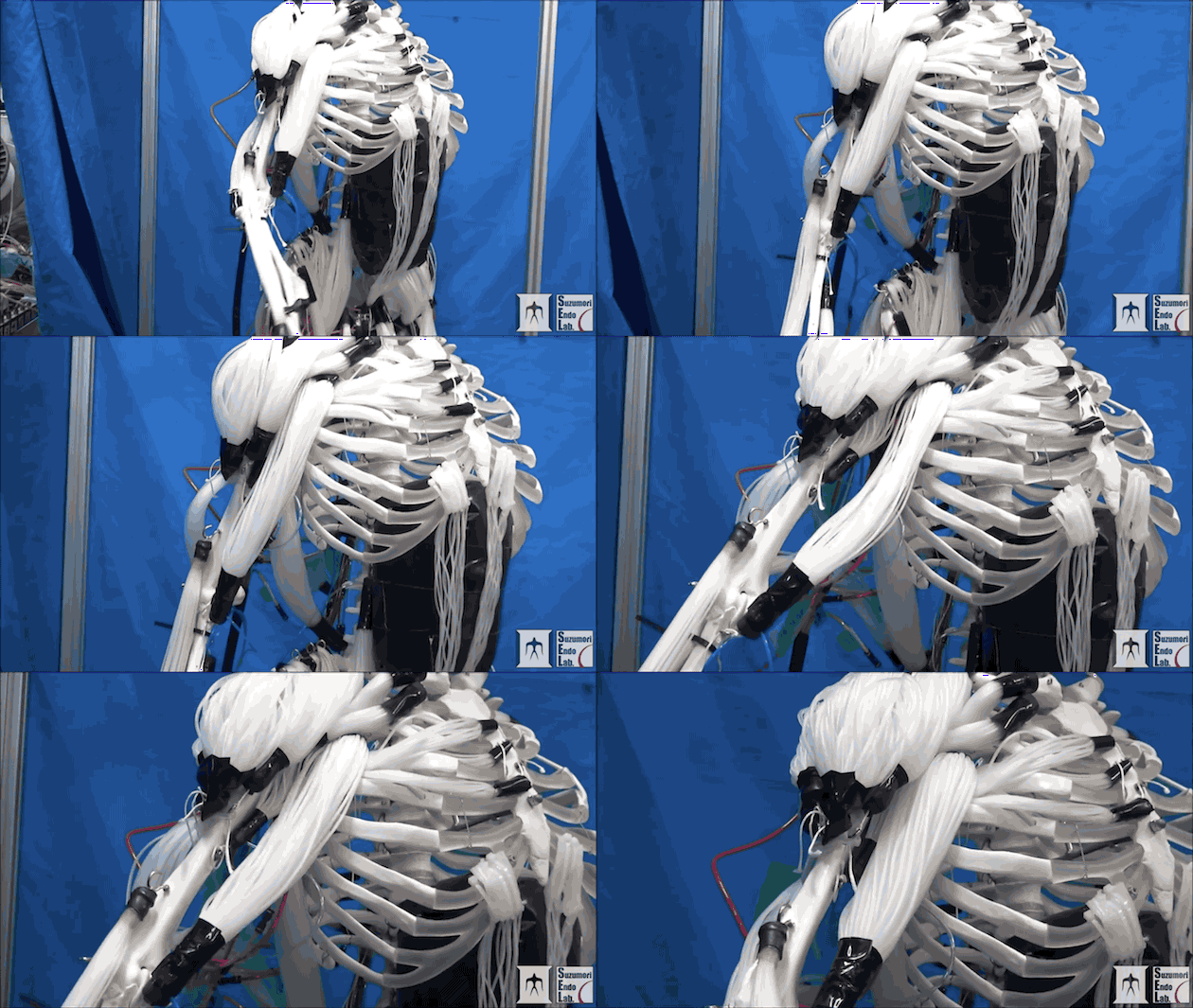
    In any manner, I'm trying to figure out how to make the McKibben hydraulic artificial muscles. And before I actually build those, I need to figure out how much force the materials will need to withstand and how much force the actuator will be able to output.

    As you may not remember, since it was many project logs ago, the best way of making the most efficient hydraulic McKibben muscles is to make a non-elastic (but flexible) bladder and make it more filament like.
    Not to mention that the easiest way to mass-produce filament-like McKibben artificial muscles is by using a small sock knitting machine.

    Sources:

    Anyway, I do need to figure out how to mass-produce the inner bladder, although I can buy kilograms of plastic tube, it would still be preferable to handmake those instead of buying, it will be expensive enough to buy the required equipment for the pump and electric motor.

    This one costs 57 dollars or 250 reais (without the taxes).

    Actually, I think I'm just overthinking the inner bladder thingie, I could "just" extrude it just like the filaments for the braided sleeve.

    In any manner, it is only left for me to find out the optimal dimensions for the materials since I intend on applying 150 bars of pressure.

    And after all of that, I need to figure out a way of making/testing/calculating the dielectric elastomer fibers, because I have a gut feeling that these braided sleeves won't be that great in the end.


    Well, I think the first approach I will attempt on how to calculate the knitted braided sleeve is to assume each hole between the braided sleeve is a ring, just like in a chainmail.

    This way I will probably find a rough estimation on how much force the fibers need to withstand in order to survive. Then I will add a safety factor of 7.

    Funnily enough, the answers I got from ChatGPT are actually almost the same, but there is something I'm finding weird. Basically, they all agred that 900kg of force would be applied to the ring area and then divide the force bewteen the six links.
    But since the tension on the links is being concentrated on 6 points, it doesn't make much sense that it would equally divide the force between linking points...

    Maybe I should've asked it to pretend it is a chain link...

    I got the answer and it keeps saying it is around 300kg or 2000kg, maybe the idea of a safety factor of 7 was...

    Read more »

  • Project Log 80: Screw it, let's freaking do it.

    FulanoDetail03/09/2024 at 15:10 2 comments

    09/03/2024, Saturday, 11:58

    This project Log was another failure, I ended up doing absolutely nothing and just yapping and yapping.

    I copy-pasted all my project logs to a google drive, it didn't pass the videos, neither some images because their link expired, but it resulted in literally 999 pages.

    999 pages of time wasting.

    Maybe I never wanted to finish this project, I just wanted to distract myself, or something. Who knows...


    Literally no one reads these logs, but sorry, I'm procrastinating a lot for some reason.

    Not just in this project, but everything in my life right now. I don't understand it either.


    I was thinking on keeping this as a draft until I actually made something, but... Right now I'm pissed and confused, so I will leave this here, I'm still adding new content whenever I actually make said content (like buying the goddang pump).

    I hate this project...

    Being honest, I feel like I hate myself more. I literally didn't even make a single scaled-down prototype of any of my ideas...


    You know what? Screw it all, let's just do it. DO IT.

    Screw efficiency, screw precision, screw reliability, screw durability, screw it all! Let's JUST DO IT.


    In any manner, let's begin with the beginning:

    • The energy source will be any kind of stationary generator that I can get my hands on, even if it means just plugging it directly to a plug in my house.

    I could find a lot of combustion engines with a single cyinder, in fact, I found a few motorcycle ones that achieved 75 horsepower.

    The problemo is that it costs 4000 reais (800 dollars).

    • I don't think that I can make any kind of electric motor that can properly work, so I was thinking of using the REB-90 number of poles and energy consumption as a basis for an air core linear brushless motor:

    I will make the coils out of casted aluminium, not the best, but cheap and easy do find and melt (easy enough, at least).

    I kinda want to use normal electric motors instead of linear motors, but for now, the production of it seems easier than the conventional one.

    The coils will be encased in silicon rubber or epoxy resin (the cheaper I can find) with the thermal paste for heat dissipation and maybe fibers for strength. 

    This means that it will looking like a thick, long spaghetti.

    The specific number of turns on each aluminium coil is still unknown to me, I still need to calculate that stuff.

    On top of that, I need to find a way of making the ESC for a brushless motor that needs to get hundreds of amps and hundreds of volts...

    One interesting fact is that I don't really know how many volts I should have since the voltage in a brushless motor defines its RPM, which would be dozens of times faster than mere centimeters per second of linear speed.

    • The structure will be any crap that I come across, be it wood, steel, aluminium or even Polyethylene.
      I don't give a damn, I will just build it thick enough until it stops breaking.

    That's it.

    Now I "just" need to do it.


    Actuator:

    The torque of the REB 90 is 300 Newton meters, and since the motor has 27cm of diameter, then a linear version would have 200kg of pulling/pushing force. But this is a spaghetti linear motor, so only pulling force.

    The kilowattage is rounded up to 80kw, but in reality it uses 60-70kw continiously. In any case, since it uses 800 volts, it would use around 100 amps. Accordingly to the AWG of aluminium wire, I would need 1AWG of aluminium wire, which is 7.5mm of diameter, almost a centimeter.
    Since it has maximum 4000 rpm with 800 volts, I would assume that its KV is 5. I don't need the speed of 4000 rpm in linear motion, but the actual number depends on the position of each linear motor.

    I forgot the number of poles and slots that the REB-90 was supposed to have...
    I did count 59 magnets and 44 slots in the 3D models that I've made. Dunno...

    Read more »

View all 92 project logs

Enjoy this project?

Share

Discussions

Similar Projects

Does this project spark your interest?

Become a member to follow this project and never miss any updates