-
Project Log 121: "Final" Project Log.31
2 days ago • 0 commentspresents significant challenges in fully replicating them within AI systems.
philosophy - Could an AI feel emotions? - Artificial Intelligence Stack Exchange
"The "instincts" in AI are algorithmic responses derived from data analysis and pattern recognition, not innate drives or feelings."
So is DNA? So are hormones? So are neurotransmitters? And neural pathways?
These instincts that humans developed come a long way since our ancestors were unicellular organisms.
And since microorganisms can develop a sense of danger, self-preservation, societal behavior and other senses, why then can't you add such things to AI?
But then, how could you pre-program things like emotions, empathy, intuition and subjectiveness to AI's?
I know that AI's don't truly feel anything, but if their programming makes them act in some way, what is the difference then?
How AI "Feels" | History of Reinforcement Learning
Humans also don't choose to feel emotions, feelings, pain and think thoughts, they do as the programming of their brain dictates.
And in most cases, just like our brain tries to fill the “holes” in our memories, it also tries to rationalize/process the “why” we do or feel certain things:
Why are you afraid of the dark? Because there are things in there. Why do you like this genre of music? Because it is good. Why do you do anything at all? Because I choose to do so, because I’m in control.
So, all you have to do is to transfer these bio-electro-chemical responses that the organic human body has to an artificial intelligence.
With all of this in mind, what is the difference between artificial intelligence and organic intelligence?
I’ve sent this to a friend of mine and he said that humans that exist today are an evolutionary result/evolutionary accident based on the constantly changing parameters of the outside world, outside of our control. Such as weather, food scarcity, meteors, earthquakes, solar flares, the ice age etc.
And that all of the things that are related to us had a reason for our survival, just like cancer-blocking genes.
Which is a very interesting point, which also makes me wonder if it would be possible to simulate…
A neural network AI that has generations, with DNA, genes, chromosomes etc…
Neuroevolution: Evolving Neural Network with Genetic Algorithms | by Roopal Tatiwar | Medium
The Evolution of Intelligence: A 600 Million Year Story.
From One Cell to a Multicellular Organism. Part 1.
What happens after 1000 hours of Evolution? Recreating the largest evolution experiment ever
This makes me want to learn programming and attempt these things, but realistically… Not even veteran specialists in the sector pulled off something like this… Dunno if I want to watch hundreds of video-tutorials of “hello world” programming…
I’m still daydreaming and superficially looking at articles and news about this stupid thing, for example:
Neuromorphic computing - Wikipedia
Optical neural networks: progress and challenges | Light: Science & Applications
The Next Generation Of Brain Mimicking AI
People quickly realized that the most efficient way possible of making/using neural networks/deep learning/machine learning algorithms is using physical neural networks with adaptable, changing logical gates.
Not so dissimilar from the human brain, in fact.
And my brain went drifting, trying to think how I would make every aspect of a physical body of a neural network like ours.
A morphological brain, a morphological growing body, a morphological energy system etc…
Plus, if the most efficient way of making artificial intelligence is making physical bodies instead of programs on conventional computers, then it may be easier to stop people from fearing a skynet situation. It can’t upload itself, because it requires too much processing power to exist. No different from human brains…
… And that also concerns me… If they would work just like human brains, feeling pain, sadness and all the other feelings. Then it wouldn’t be different from enslaving another human…
… Which made me remember of the “Ex Machina” movie:
Ex Machina (4/10) Movie CLIP - How Ava Was Created (2015) HD
… Which makes me wonder:
We are not making an “artificial intelligence” per se, but a synthetic human intelligence.
There is always the thought that if there are sentient extraterrestrial life-forms, they can be so extraordinarily different from us that we may not even consider them life-forms.
And the closest thing to an alien would be artificial intelligence, an intelligence that supposedly, wouldn’t work like us, that it would be completely different from us.
Yet…
Well, while daydreaming about this subject and looking around the internet, I remembered about the self-assembling wires videos that I saw a reeeeeally long while ago.
It is pretty simple in essence, using nanowires and/or nanoparticles, the electricity will essentially work like an electrodeposition. Where atom by atom is layered upon an electrode until the suspension either runs out of material or until it makes a dendrite. And thus, the electrical current will do that using the shortest path possible.
That, in turn, would look and work just like neurons.
In the video it uses thousands of volts, but at nanometric distances you would need a maximum of a few volts maximum.
Brain-Like (Neuromorphic) Computing - Computerphile
![]()
Sources: https://arxiv.org/pdf/1712.09497 We built a ‘brain’ from tiny silver wires. It learns in real time, more efficiently than computer-based AI
https://youtu.be/xuL2yT-B2TM (maybe you could use this to continuously make the structure to change or even “hard reset” to the start?)
Fabrication and Training of 3D Conductive Polymer Networks for Neuromorphic Wetware
Teslaphoresis: Nanotube wires self-assemble under the influence of Tesla Coil
Self-Assembled Wires in RamZland!⚡️ #STEM #RamZland #HighVoltage #ScienceForKids
Self-Assembling Wires in Petri Dish with High Voltage
Self-Assembling Wires | 10kV High Voltage Demonstration
Self-Assembling Wires That Plug Themselves In - YouTube
https://www.youtube.com/watch?v=WtA-CEzKRL8
Toward Multifunctional Liquid Metal Composites
Self-Assembling Wires | 10kV High Voltage Demonstration
Self-Assembling Wires That Can Solve a Maze!
Directed Assembly of Liquid Metal–Elastomer Conductors for Stretchable and Self‐Healing Electronics
https://www.youtube.com/shorts/JC_SoZj5Na8
Nanotubes assemble! Rice introduces Teslaphoresis
https://www.youtube.com/shorts/2n98-bJ90js
Teaching self-assembling structures a new trick | MIT News
Small diamonds create self-assembling wires - EE Times Asia
Self Assembling Wires? Levitating Motor? LATITY-005?!
Self-Assembling Polymers Provide Thin Nanowire Template | Lab Manager
Researchers Use World's Smallest Diamonds to Make Wires Three Atoms Wide | Lab Manager
Linear self-assembling of porphyrins via metal coordination
Self-Assembling Wires – Stanford Complexity Group | Systems Community of Inquiry
Nanotubes assemble! Rice introduces Teslaphoresis
All-memristive neuromorphic computing with level-tuned neurons - IOPscience
Neuromorphic computing mimics important brain feature
A neuromorphic computing architecture that can run some deep neural networks more efficiently
I’m just absolutely baffled by it, because it is essentially how you make extremely complex systems with incredibly simple rules. It always was in front of us and we simply looked at it with a different perspective…
Which also makes me wonder: if you used biocompatible conductive materials, wouldn’t that mean that you can (maybe, perhaps, who knows) literally add neurons to your brain?
Maybe this could help people with brain damage…? 🤔
I was also wondering about how much material and which specific materials I would need to make this neuromorphic computer:
I asked both for DeepSeek and ChatGPT:
“To transform your conductive particle system into a neuromorphic computer, you need to incorporate features that emulate biological neural networks—adaptive synapses, neurons with non-linear activation, memory, and learning mechanisms. Here’s a structured approach:
Key Additions for Neuromorphic Functionality
- Synaptic Plasticity (Adaptive Connections)
- Memristive Particles: Use materials like TiO₂, AgS, or conductive polymers that change resistance based on voltage history. These act as artificial synapses, enabling Hebbian learning (strengthening/weakening connections through activity).
- Dynamic Pathways: Apply voltage pulses to modify particle arrangements (e.g., via electrochemical reactions) to mimic spike-timing-dependent plasticity (STDP).
- Neuron-like Non-linearity
- Threshold Materials: Introduce particles with non-linear I-V characteristics (e.g., vanadium dioxide or chalcogenides) that exhibit abrupt conductivity changes at specific voltages, mimicking neuronal "firing."
- Network Architecture
- Structured Electrodes: Add a grid of electrodes (not just two) to create layered input/output/hidden "neuronal" layers. This allows parallel processing and complex signal routing.
- Compartmentalization: Divide the container into regions (e.g., using insulating barriers) to simulate dendritic/axonal segregation.
- Memory Integration
- Phase-Change Materials (PCMs): Embed particles like GeSbTe (GST) that retain structural states (amorphous/crystalline) to store information long-term.
- Hysteretic Fluids: Use ferroelectric or magnetorheological fluids to preserve transient states.
- Learning Algorithms
- Voltage Patterning: Train the system with spatiotemporal voltage sequences to reinforce specific pathways (e.g., reward/punish signals via backpropagation-like feedback).
- Feedback Loops: Integrate sensors/actuators to close the loop between input data and output behavior (e.g., optical/thermal feedback).
- Energy Efficiency
- Low-Power Materials: Optimize particle conductivity and electrode design to operate at biologically plausible voltages (mV to ~1V).
- Pulsed Operation: Use sparse, event-driven signals (like biological spikes) instead of continuous currents.
Example Implementation
- Particles: Mix memristive nanoparticles (TiO₂) with phase-change (GST) and threshold (VO₂) materials.
- Liquid Medium: Use a dielectric fluid (e.g., silicone oil) to allow particle mobility while preventing unintended shorts.
- Electrodes: Deploy a 3D electrode array to stimulate/track pathways in multiple dimensions.
- Control System: Interface with a microcontroller applying STDP-like voltage pulses to "train" the network.
Challenges to Address
- Scalability: Ensuring consistent particle behavior in large systems.
- Stability: Preventing particle agglomeration or drift over time.
- Readout/Interface: Developing methods to decode the network’s state (e.g., impedance tomography or optical monitoring).
Outcome
Your system could evolve from forming static conductive paths to emulating a spiking neural network capable of unsupervised learning (e.g., pattern recognition, adaptive control). This bridges morphological computing (physical optimization) with neuromorphic principles (brain-inspired computation).
To determine the precise kilograms of materials required for building a morphological/neuromorphic computer based on conductive and memristive particles in a liquid medium, several factors must be considered: material properties, particle density, device architecture, and functional requirements. While exact quantities depend on the scale and design of the system, here’s a framework based on research insights and material synergies from the search results:
Key Components & Material Ratios
1. Conductive Particles/Nanowires
Role: Form percolation networks for charge transport.
Materials: Silver nanowires, carbon nanotubes, or graphene flakes.
Quantity: ~20–40% of the total particle volume.
Example: For a 1-liter container, ~200–400 grams (assuming particle density ≈ 1–2 g/cm³).
Design Note: Ensure particle density exceeds the percolation threshold for continuous pathways 410.
2. Memristive Particles
Role: Enable synaptic plasticity and memory via resistive switching.
Materials: TiO₂ (titanium dioxide), WO₃ (tungsten oxide), or AgS (silver sulfide).
Quantity: ~5–15% of the particle mixture.
Example: 50–150 grams per liter.
Design Note: TiO₂-WO₃ hybrids enhance linearity and stability in conductance changes, critical for neuromorphic learning 412.
3. Neuron-like Non-linear Materials
Role: Mimic neuronal firing through threshold-driven conductivity changes.
Materials: Vanadium dioxide (VO₂) or chalcogenides (e.g., Ge₂Sb₂Te₅).
Quantity: ~5–10% of the mixture.
Example: 50–100 grams per liter.
Design Note: VO₂ exhibits abrupt metal-insulator transitions at specific voltages, ideal for spiking behavior 14.
4. Memory Integration Materials
Role: Long-term data retention and phase-change memory.
Materials:
GeSbTe (GST): Phase-change particles for non-volatile memory.
Ferroelectric fluids: Barium titanate (BaTiO₃) nanoparticles in oil.
Quantity: ~10–20% of the mixture.
Example: 100–200 grams per liter.
Design Note: GST’s amorphous/crystalline transitions enable multistate storage 412.
5. Dielectric Fluid
Role: Stabilize particle dispersion and prevent short circuits.
Materials: Silicone oil, fluorinated fluids, or ionic liquids.
Quantity: ~50–70% of the total volume.
Example: 500–700 grams per liter (fluid density ≈ 0.9–1.5 g/cm³).
Design Note: High dielectric strength fluids (e.g., silicone oil) reduce leakage currents 412.
6. Electrodes & Structural Additives
Role: Input/output interfaces and network control.
Materials:
Electrodes: ITO (indium tin oxide) for flexibility, platinum for stability.
Barriers: Insulating polymers (e.g., PET) for compartmentalization.
Quantity: Electrode mass depends on surface area (e.g., 1–5 grams for a 10×10 cm² grid).
Example Calculation for a 1-Liter Prototype
Component Material Mass Range (grams) Key Function
Conductive particles Ag nanowires 200–400 g Charge transport
Memristive particles TiO₂-WO₃ 50–150 g Synaptic plasticity
Non-linear material VO₂ 50–100 g Threshold firing
Memory material GeSbTe 100–200 g Phase-change storage
Dielectric fluid Silicone oil 500–700 g Dispersion medium
Electrodes ITO/Pt 1–5 g Signal input/output
Critical Considerations
Particle Size & Distribution:
Nanoparticles (1–100 nm) ensure homogeneous dispersion and efficient switching 414.
Larger particles (>1 µm) may cause agglomeration and instability.
Scalability Challenges:
Memristive materials like TiO₂ require precise doping (e.g., oxygen vacancies) for reliable switching 1012.
Phase-change materials (GST) need thermal management to prevent unintended state transitions 4.
Empirical Testing:
Optimize ratios via impedance spectroscopy and cyclic voltammetry to balance conductivity and memory effects 12.
Energy Efficiency:
Low-voltage operation (<1 V) reduces power consumption, critical for neuromorphic systems 410.
Conclusion
While exact kilogram-scale recipes remain experimental, the above framework aligns with studies on hybrid memristive systems 41214. Start with small-scale prototypes (e.g., 100–500 mL) to refine material ratios and electrode configurations. For industrial-scale production, consult nanomaterial synthesis protocols and scalable deposition techniques (e.g., sputtering, inkjet printing) highlighted in the search results 414.”
ChatGpt suggested basically the same thing, but it also added the necessity for a graphene oxide addition to work as a transistor:
“In Summary
- To Convert Flash Graphene to Graphene Oxide:
- Reagents Needed: Concentrated sulfuric acid (H₂SO₄), phosphoric acid (H₃PO₄), potassium permanganate (KMnO₄), hydrogen peroxide (H₂O₂), and deionized water.
- Process: Mix graphene in the acid mixture, slowly add KMnO₄ under cooling, let the oxidation proceed, then quench the reaction with water and H₂O₂, and finally wash and centrifuge to purify the GO dispersion.
- To Build a Morphological Computer:
- Suspension: Disperse your (reduced) graphene oxide flakes in an electrically insulating fluid (such as silicone oil).
- Electrodes: Place metallic electrodes at the boundaries of a container holding this suspension.
- Functionality: Under an applied electric field, the GO/rGO flakes self-organize (for example, forming a conductive “shortest path”) which can be “read” as the computed output.
This combination leverages the ease of making graphene (via the flash method), its conversion to GO through chemical oxidation, and the use of GO’s self-assembly behavior in an insulating medium to create a rudimentary morphological computer.
References:
(discussing 2D materials and transistor-based neuromorphic devices)
(general background on organic and molecular electronics)
(NOMFET and related bio-inspired transistor devices)*
Even assuming that both ChatBots are completely correct in every affirmation, how can I make this (stupid cheap self-assembling) computer work?
How do I make a program to train, modify and interpret all of these signals reliably?
Well, in theory, the computer is the only machine that can simulate another machine with more processing power.
You could simulate all the computational power of a super powerful supercomputer in a conventional calculator, but it would take decades to do so.
However, I was wondering about the possibility of using this neural network to simulate a conventional computer and use it like any other computer.
You would be able to literally build a computer by mixing a bunch of powders together. 😐
By the way, there are around 100 miles (160 kilometers) of interconnects in microprocessor chips.
How much ‘wiring’ is inside a 4th Gen Intel Xeon Scalable processor? - YouTube
I say this because I think you would need a similar amount of electrodes connecting the Neuromorphological Biomimetic Computer (NBC) to the external world, both for training and monitoring.
So, assuming that the copper wires are in the 43 AWG (0,056 mm), a 100 mile copper wire with this diameter would weigh around 3 kilograms. With 34 AWG (0,160 mm), it would weigh 25 kilograms.
The worst part would be wiring everything together… You would need to wire 160 kilometers of this crap…
How would you make the electrode array?
I thought of printing electrode arrays into PVA foils, then adding a layer of the powder that would be the NBC, wire everything, dissolve the PVA with a mix of water and alcohol, and finally, remove all the water and add the silicone oil Leaving behind a super dense layer of electrodes.
![]()
I thought of making and then wiring everything like the image above, so: You would organize a bunch of wires side-by-side on a table, add a silver tape to keep everything in place and connect one part to the electronic systems and the other to the electrode array.
The thing is, I think you could use conventional rubber insulated wires (small ones) for the connection from the electrodes to the outside. The important part that would be inside the NBC box would already obey the 160 km rule with minimum weight.
About the design of the electrodes themselves, I don’t know which design to choose.
![]()
![]()
Sources: Phase-shift feedback control for dielectrophoretic micromanipulation (PDF) Stretchable Micro-Electrode Arrays for Electrophysiology
This was the same electrode array used on that video from the Thought Emporium channel.
Working Neuron Arrays! | DOOM Neurons Part 2
![]()
What Computers are Made From (I found these randomly on pinterest)
Speaking of self-assembling wires… Now that I think about it, what about the possibility of self-assembling actuators and/or other structures?
Well, I can’t find anything that is somewhat simpler, like the neuromorphic brain. And yes, I asked ChatGPT and DeepSeek and I obviously get washed out answers that don’t try to think weirdly like humans do.
(here I will only list the ones that are relevant for structures, you still need to check the links on neuromorphologic brain computer’s links I listed)
Self-assembly based manufacturing - Wikipedia
Programmable matter - Wikipedia
3D microfabrication - Wikipedia
ECAM 3D Printing Explained: Advanced Metal 3D Printing by California Technical Media (I posted this one before, but you could use other materials that aren’t copper)
While talking about electrodeposition, the “best” idea I had was to have a bunch of electrodes (like carbon fibers) submerge them into a mixture of flexible insulating materials and conductive materials (like the neuromorphic brain thingie), pass the current to align the particles and melt everything in place. That would work like a dielectric elastomer actuator. I think. Maybe. Supposedly. Who knows?
I also thought of using a mold with multiple fiber electrodes in a mixture of insulating liquid (like silicon oil), disperse the materials and make some kind of foam/aerogel. Then finally thermosetting everything by partially melting things, like in sintering and then infusing it with a mix of epoxy and glass fiber on the outer-shell. But it would be interesting to make everything in a single “growth”.
I did talk a lot about electrodes in these ideas, but I was wondering about the possibility of using induction coils to induce a high voltage and/or high amperage inside the mold, so everything would be electrically stimulated in an uniform way. Not allowing all the good stuff to accumulate in a single electrode.
Resonance Experiment! (Full Version - With Tones) (maybe said induction coils could work on sound frequencies in order to make the powder/fluid to organize in specific ways, just like salt grains organize under specific frequencies)
Seeing Sound With Sand | Soundwaves: The Symphony Of Physics | BBC Earth Science
CYMATICS: Science Vs. Music - Nigel Stanford (it does makes me wonder if organizing powders of different densities, they would move a little more or a little less, allowing the organization of to-be-sintered powders into microlattices)
8 CRAZY experiments with SOUND!
Cymatics full documentary (part 1 of 4). Bringing matter to life with sound
Small cubes that self-assemble
Investigation Seeks to Create Self-Assembling Materials
A swarm of a thousand kilobots self-assembling into different shapes. (Rubenstein et al., 2014).
Porosity and Permeability Demo
Electroplating Carbon Fibers Can Have Interesting Results | Hackaday
Self-Created Metal Composites | Hackaday.io
SMiA. Structural Morphology in Architecture Summer Workshop. 2016
System Self Organization - YouTube
Atomic-scale combination of germanium-zinc nanofibers for structural and electrochemical evolution
Synthetic morphology with agential materials | Nature Reviews Bioengineering
(PDF) Nanoscale self-assembly: Concepts, applications and challenges
Recent Developments in Self-Assembling Multi-Robot Systems | Current Robotics Reports
Self-Assembly in Micro- and Nanofluidic Devices: A Review of Recent Efforts
A self-organizing robotic aggregate using solid and liquid-like collective states
Atomic Brain? - Computerphile (This one makes me remember about the positronic brains in Isaac Azimov’s novels, he never delves into details, but he does mention that the 3 laws are controlled by coils. So it could be that the “brain” of the robots worked just like this suspended atom, but using positrons instead. Even though his novels always delve into how the three laws aren’t fail proof, I do wonder how you could add external neural networks that could control the positron/atoms in these brains in order to avoid certain actions and learning faster)
Can We Build an Artificial Hippocampus?
A Surprising Way Your Brain Is Wired
Building Blocks of Memory in the Brain
How Your Brain Organizes Information
Brain Criticality - Optimizing Neural Computations
How does electricity find the "Path of Least Resistance"?
Gradient Descent vs Evolution | How Neural Networks Learn
As much as I’d love to test this out, I don’t think I have enough knowledge and resources to test this out.
Non-invasive Brain-Computer Interface:
SPEAKING OF BRAINS: I don’t have one, that’s why I’m writing this project log.
![]()
(side and front view of me)
Brain–computer interface - Wikipedia
In any manner, computer-brain interfaces are really hard to make without being invasive.
New Brain-Computer Interface (BCI) Allows Man with ALS to 'Speak’ Again Using Brain Implant and AI
But there is research™.
In essence, you need two things:
- An imaging system that can measure neurons directly.
- Neuroimaging - Wikipedia
- Magnetic resonance neurography - Wikipedia
- Positron emission tomography - Wikipedia
- Magnetic resonance imaging - Wikipedia
- Diffuse optical imaging - Wikipedia
- Cranial ultrasound - Wikipedia
- Magnetoencephalography - Wikipedia
- Functional ultrasound imaging - Wikipedia
- Electroencephalography - Wikipedia
- Neuropixels - Wikipedia
- A feedback System that can stimulate specific areas of the brain.
- Neurostimulation - Wikipedia
- Non-invasive cerebellar stimulation - Wikipedia
- Transcranial pulsed ultrasound - Wikipedia
- Transcranial magnetic stimulation - Wikipedia
- Cranial electrotherapy stimulation - Wikipedia
- Transcranial direct-current stimulation - Wikipedia
- Transcranial random noise stimulation - Wikipedia
(I asked ChatGPT and DeepSeek and both said that I would need a voxel resolution of at least 3mm for a brain-computer interface)
The first thought I had was either making a microwave tomography machine or a cryogen-less MRI machine, how hard can it be, riiiigh?
However, due to how it works, it is really difficult to make it mobile and/or compact.
But there is research™.
![]()
Sources: https://www.fanaticalfuturist.com/2020/09/university-researchers-unveil-the-worlds-first-portable-mri-machine/ MR SOLUTIONS BRINGS DRY MAGNET TO 9.4T MRI SYSTEM - QMISG
Both cryogen-free (doesn’t use liquid helium/nitrogen) and both weigh around 700kg.
I also had a loooong train of thought on trying to figure out how I could make microwaves/radiowaves to focus in 1mm voxels in order to make a viable, compact and cryogen-free MRI machine/microwave tomography machine. But as you can imagine, like anything in this project log, I couldn’t find a single example in real life using those ideas.
And even if you were able to achieve such high resolution with microwaves, you wouldn’t be able to measure the neurons firing by itself. Only the super ultra small changes in dielectric constant inside your brain.
The best tomography system would be using x-rays or electrons. The first is lethal during continuous exposures and the second can only go through the brain if you use a particle accelerator.
What if you put your hand in a particle accelerator?
What if you put your head in a particle accelerator?
THe only way to make this work would be by having these waves suddenly going out of the center of your brain, which an MRI machine already does.
Well, the best and “”””simplest”””” method of imaging that seems practical to DIY is through magnetoencephalography.
It simply detects the currents the neurons produce by measuring its magnetic fields, which are in the 1000 to 10 femto-tesla’s scale, 1,000,000 to 100,000,000 times smaller than a microtesla.
Although there are the obvious options of using superconductors as magnetometers, the optically pumped magnetometer “simply” shines a laser to a vapor of alkaline metal (such as rubidium, cesium or potassium) and measures the changes in the cloud of atoms. Which seems the most promising for me.
Synthetic-aperture magnetometry - Wikipedia
Most imaging systems are said to only be able to detect and translate the signals emitted from the neurons in the brain in time frames around 1 to 7 seconds, the best ones have time frames of a few hundreds of milliseconds.
100 milliseconds can be considered fast, but have you ever played a game with 100 milliseconds of ping delay?
(imagine this in a mech)
I’m not sure if this is due to the hardware that they used, so I’m not sure if “simply” increasing the computational power would suffice…
So… Well…
If you are using an Optically Pumped Magnetometer, the best option for brain stimulation is to use ultrasound. Since the transducer can work by using a laser instead of piezoelectric crystals.
Which is another problem with OPM’s… Literally ANYTHING will be detected by the system. It is so sensible that if you have anything electrically conductive, it will add a noise source to the system.
Applying magnetic fields to conductive materials induces an electrical current, and that electrical current creates its own magnetic field.
Yes, even something as infinitely small as a neuron’s magnetic field will induce an equally infinitely small electric field.
That only happens because magnetic fields are infinite (if I'm not mistaken).
Which makes me wonder: if it induces such small currents, then can nanometer-sized electrodes work as magnetometers?
Converse Magnetoelectric Composite Resonator for Sensing Small Magnetic Fields | Scientific Reports It “””only””” detected 70 pico-teslas at 10 hertz operation. Well, it is a passive resonator, not a detector, and since it doesn’t resonate anything below its detection level, it is not useful for this specific application. Still, it’s simply a brilliant piece of engineering since it can do that passively. Maybe it could be used as an indicator for the amount of magnetic noise inside a chamber.
Femtotesla Magnetic Field Measurement with Magnetoresistive Sensors This one works at 77 kelvin or -196ºC/-321ºF, liquid nitrogen temperature. You can still reach that with pulse tube cryocoolers, like the ones made by Hyperspace-pirate. Making Liquid Nitrogen with my Homemade Cryocooler
Ultra-Compact Magnetoelectric Sensor for Femto-Tesla VLF Signal Reception - ScienceDirect
(PDF) A hybrid magnetometer towards femtotesla sensitivity under ambient conditions (this one seems interesting)
Just now it occurred to me that I didn’t even wonder what is the minimum amount of strength required to be detected for a functional “good enough” Magnetoencephalogram.
ChatGPT:
“Magnetoencephalography (MEG) is a non-invasive technique that measures the magnetic fields produced by neuronal activity in the brain. These magnetic fields are extremely weak, typically ranging from 10 to 1000 femto-tesla (fT). Detecting such minute signals requires highly sensitive equipment.
Superconducting Quantum Interference Devices (SQUIDs) are currently the most sensitive magnetometers available and are commonly used in MEG systems. SQUIDs can detect magnetic fields as low as a few femto-tesla, making them suitable for measuring the brain's magnetic activity within the specified range.
Minimum magnetic field detected and measured
Research indicates that the minimum detectable dipole strength under typical experimental conditions is about 4.5 nanoampere-meters (nAm), which corresponds to magnetic fields on the order of 100 femto-tesla. This sensitivity is adequate for detecting evoked neuronal activity, which often produces dipole strengths in this range.
There is also near-infrared brain imaging and high array density electroencephalograms, but these can only “see” the surface of the brain instead of everything.
Well, near-infrared is also ruled out since it only monitors the blood flow in the brain…
But that also makes me wonder, which part of your brain needs to be mapped in order to make a non-invasive computer-brain interface?
ChatGPT:
“Most BCIs work by interpreting signals generated in the sensorimotor region—especially the primary motor cortex. This area, located in the precentral gyrus, is responsible for planning and executing voluntary movements. Mapping the motor cortex allows researchers to decode the user’s intended movements and translate these into computer commands, which is the core functionality behind many brain–computer interfaces.
For example, many state‐of‐the‐art systems, such as Synchron’s stentrode, are designed to record activity from the motor cortex, making it possible to control devices (like a computer cursor or even smart home appliances) using thought alone
https://www.thetimes.co.uk/article/brain-implant-thats-ahead-of-elon-musk-in-the-race-to-read-minds-mwfp0233n
In addition, similar approaches have been used in clinical trials and research studies to enable communication and mobility in patients with paralysis
NY neurotech company’s brain implant allows ALS patient to control Amazon's Alexa with thought
While other areas (such as the somatosensory or prefrontal cortices) can also be mapped to enhance feedback or cognitive control, the primary motor cortex remains the most critical target for creating an effective computer–brain interface.”
![]()
Sources: Motor cortex - Wikipedia Dorsolateral prefrontal cortex - Wikipedia
… So all of the required parts to be mapped are literally on the surface of the brain, not requiring anything too complex... 🤡
I asked ChatGPT about high density EEG:
“The answer isn’t a single fixed number—it depends on many factors (number and placement of electrodes, quality of the head model, noise level, and the specific inverse method used). In practical, non‐invasive HD EEG studies using advanced source localization (e.g., methods such as sLORETA, LAURA, or other distributed approaches with individualized head models), typical localization errors are on the order of 7–10 mm. In other words, while “high‐density” EEG (using 128–256 channels) does dramatically improve the effective spatial resolution compared to traditional 19–21 channel systems, most empirical studies report that the best‐achieved accuracy (i.e. the average localization error when compared against gold‐standards such as fMRI or intracranial recordings) tends to be around 7 mm.
There have been simulation studies—and even some experimental work under ideal conditions—that suggest it might be possible to push the limits further (toward a few millimeters). However, to date no robust, reproducible human study using noninvasive scalp recordings has consistently demonstrated a practical spatial resolution as fine as 3 mm. In clinical and cognitive neuroscience applications, achieving a resolution around 3 mm remains more an aspiration (or a theoretical limit under very favorable conditions) than a routine outcome.
For example, one study comparing EEG source imaging of visual evoked potentials with high‐resolution fMRI found that the mean localization error was about 7 mm, which is sufficient to detect changes in visual field representation but not at the 3 mm level.
Assuming that I am unable to replicate the femtoscale magnetometers I previously mentioned, maybe if you use a mix of both cryogen-free compact pulsed MRI, ultra high density Electroencephalogram arrays (with thousands to millions of electrodes) and microwave tomography, you could make a good-enough system.
In the case of the compact MRI, I should use a “phased” MRI machine. It would work just like those rotating ones. And on top of that, I would need to use the technique used for real-time scanning. Normally the MRI machine needs to wait for those spinning protons to relax and detect the radio/microwave they emit.
Even so, you could use the picoscale magnetic field resonator to help increase the signal of the collapsing magnetic fields. Assuming that the MRI machine doesn’t do that already.
MRI pulse sequence - Wikipedia
Pulsed field gradient - Wikipedia
Phased Arrays - Steering and the Antenna Pattern | An Animated Intro to Phased Arrays
If it is pulsed, then, maybe it could also work as a transcranial magnetic stimulation.
Home Made MRI 2+1/2 | Hackaday.io
Imaging a brain thinking, using a new MRI technique.
Deep Learning Algorithms for Brain Disease Detection with Magnetic Induction Tomography (there is also Magnetic induction tomography, which seems promising for surface scanning, but there isn’t much material on it, the wikipedia page only describes what it is)
Rapid Electromagnetic Induction Imaging With an Optically Raster-Scanned Atomic Magnetometer
Can MRI Be Used as a Sensor to Record Neural Activity? - PMC.
Direct magnetic resonance detection of neuronal electrical activity - PMC
Five steps to make MRI scanners more affordable to the world
MRI for all: Cheap portable scanners aim to revolutionize medical imaging | Science | AAAS
A low cost, portable prototype MRI machine
A portable scanner for magnetic resonance imaging of the brain | Nature Biomedical Engineering
Advance Low-field Portable Magnetic Resonance Imaging (MRI) by Applying Electromagnetics Concepts
Portable scanner could boost point-of-care brain MRI – Physics World
Whole Body Sodium MRI at 0.5 Tesla Using Surface Coil and Long Echo Time Sequence
-
Project Log 120: "Final" Project Log.30
2 days ago • 0 commentsJust saw this video: I built a 1,000,000,000 fps video camera to watch light move It may be useful for the plasma system for detecting the speed and position of projectiles.
An obvious solution would be to fill the surface of an object with electrodes, but the electrodes would take too much time to build, check and maintain.
![]()
Sources: Basic Concepts of Plasma Generation | SpringerLink https://www.ialtenergy.com/dpf.html
The first and second images are an example, where the electrodes are in an array and the magnetic fields would contain the plasma. Making multiple “scales” around the body of the object.
I don’t think there is a way of making a bigger shield, I think it would be better to make something like the dense plasma focus structure. Except airflow would be coming out of the tubular electrodes, making a shell-like plasma field around a part
An air knife is just an arrangement of nozzles that make airflows in a very specific way.
Streamtek Regular Air Knife Explanation
Air Consumption Open Pipe vs Air Knife
I thought about the possibility of a non-thermal "open tokamak" with an air jet of cold-plasma, but I mean...
![]()
Source: (PDF) ARTIGO: ENERGIA ELÉTRICA VIA FUSÃO TERMONUCLEAR CONTROLADA # PAPER: ELECTRIC ENERGY VIA CONTROLLED THERMONUCLEAR FUSION
That would already be super complicated in itself… But how would I detect the incoming projectile? How would I melt specifically the incoming projectile, like the previous ideas? I would need to heat so much of the surrounding air that it would need unviable amounts of energy.
![]()
Sources: High frequency instability of a magnetized spherical electron sheath Sheaths and Boundary Layers
These last two images are the ones that mostly look like an actual energy shield, but it is just a round electrode in a near-vacuum chamber. So if you wanted to make that work, you would need to essentially make the entire object into an electrode…
Which comes back to the problem of: how to selectively melt incoming projectiles? If I need to heat up everything, it would need so much energy it would be impractical.
I think the only way would be to make “lines” and use intermediate electrodes to guide these lines.
![]()
Take a magnetic field of a solenoid as an example, it is a torus, take the image of the torus on the right and take out all the horizontal lines, leaving only the vertical lines.
Imagine that each single one of the lines starts from a pointy electrode and they go from the top directly to the bottom, meeting a single spherical electrode.
The intermediate electrodes and the magnetic field would guide these lines, each one of these electrode lines would also be a sensor to detect incoming projectiles. If you fit enough vertical lines, it will be able to cover the entire object.
![]()
The issue is: how to fit the mech inside of it?
It is straightforward enough to encompass a ship or other shapes, but a mech?
![]()
Found this gif randomly on one of those pseudoscience accounts on pinterest, although it tries to imply humans have some kind of “harmony field”, it seems it could work for the electromagnetic field of an energy shield.
5 toroids, one on the torso and one in each limb, they all converge on the top.
🔶🔶🔶🔶
(I will write these orange squares to keep track of parts where I’m procrastinating, so I finish them already)
How to make humans dodge bullets in real life:
The idea is pretty simple actually:
- Take that nanosecond camera that can see light moving through air
- Add the HUD screen to the human viewer as a faded image that shows what is happening as something that will happen.
- And that’s it.
Like a “precognitive vision” so to speak.
The HUD would show you a prediction of what would happen in a way you would have time to react. World's Most Advanced HUD | Real Life Power Armor (Part 3/6) Rudeus Beat Eris In Sword Fight By Using Demon Eyes |Mushoku Tensei: Jobless Reincarnation S1 Ep 12| (this is the only example that I could think of at the moment)
Tanks and missiles already do that using rangefinders to predict where to point based on speed, direction and position of said targets.
Trajectory Prediction & Collision Detection
The Missile Knows Where It Is, But It's Actually A Javascript Tutorial
Real-time Pedestrian Trajectory Prediction
Funny thing is: this wasn’t even my idea, it was suggested by ChatGPT.
I was wondering about how you could make a hypothetical human-computer-interface to work in real life without giving full control to the AI while taking into consideration the limit of human perception.
The computer can see the bullet coming, but a human can’t. So how do you solve it?
Then ChatGPT suggested:
You make the computer calculate the trajectory of the bullet and show it to the human as a “precognitive vision”, something that will happen.
Predicting what can happen, not what will happen.
(assuming this can be done in real life) That would still have some flaws.
The computer can only make an approximation of what can happen heavily depending on your perception of time and your reaction speed to deal with the threat.
So if you are going around a corner and someone throws something at you behind it you wouldn’t be able to see it coming, because you wouldn’t be fast enough to access the situation and dodge.
Adaptive fluid armor/Rheological Armor:
Well, I don’t want to make anything to hurt other people, but making ballistic armor doesn’t count, right?
In any manner, for some reason I got the “funsies” for an armor that is completely malleable, but hardens during impact.
Non-Newtonian fluid - Wikipedia
Dilatant - Wikipedia (for some reason they are also called dilatants)
Shear-thickening fluids, magneto-rheological fluids, electro-rheological fluids are all rheological fluids.
In a dumb-down manner (which is the manner that I understand things), a “rheological” material is any kind of material that has a property that is “activated” depending in a specific manner.
Either on impact, electricity, magnetism, chemically, under light etc.
https://youtu.be/ejRFQaIsvj0?t=180 (deus ex: Mankind divided)
https://deusex.fandom.com/wiki/Titan
"Titan, stylized as TITAN, is an experimental augmentation in Deus Ex: Mankind Divided. A neodymium skin underlay matrix built of nano-meshed rare earth magnets and powered with hook-ins to the Biocell electrical system, the TITAN skin augmentation can be activated at will and then dissipated instantaneously. The neodymium underlay is installed with a few thousand ampoules of dimorphic magnetorheological fluid (a carbonyl iron mix with a prismatic foam nano-structure). When activated, the fluid is ejected from tiny nozzles installed throughout the skin. Simultaneously, the neodymium underlay electrifies, causing the fluid to solidify and seal the user inside an iron shell, effectively protecting them from all physical damage."
I don’t think that neodymium would be strong enough to make a strong magnetorheological fluid armor tho…
![]()
Although you are familiar with a shear-thickening fluid/non-newtonian fluid/dilatant made out of polyethylene glycol and silica nanoparticles, this is not a “real” shear-thickening fluid.
Polyethylene glycol is a shear-thinning fluid, which decreases its viscosity based on shear stress. So, I think that when you add silica as a colloidal dispersion and the fluid suffers stress, the PEG gets such a low viscosity it starts to act like a superfluid. Flowing away from the particles and creating a vacuum… I think I'm probably just talking garbage…
Well, in any manner, I was wondering about the possibility of combining as many rheological properties as possible on the most viscous fluid on the planet, mixed with rubber and see if it would be strong enough to stop bullets by itself.
ChatGPT suggested a bunch of rheological activation types, but I streamlined them down to a few that could be viable/possible/practical to use:
- (keep in mind that ChatGPT may just be making sh1t up)
- Photo-rheology Materials whose rheological properties are influenced by light exposure. Common in photopolymers and certain smart materials that harden or soften under UV or visible light.
- Pressure-sensitive Rheology Materials whose viscosity or flow properties change with applied pressure. Example: certain elastomers and polymers under high-pressure environments.
- Acousto-rheology Involves changes in rheological behavior under the influence of sound waves or ultrasonic vibrations. Used in emulsions, suspensions, or certain gels.
- Baro-rheology Describes materials whose rheological behavior is sensitive to barometric (atmospheric) pressure changes, particularly in gases or aerated materials.
- Capillary Rheology Focuses on the flow behavior of fluids in confined spaces, such as in thin capillaries or porous media.
- Extensional Rheology Studies the behavior of materials under extensional (stretching) stresses rather than shear stresses. Crucial for fiber spinning and film formation.
- Self-healing Rheology Focuses on materials with the ability to recover their rheological properties after being disturbed, common in some gels and polymer systems.
- Electrorheological fluid - Wikipedia Electrorheological (ER) fluids are suspensions of extremely fine non-conducting but electrically active particles (up to 50 micrometres diameter) in an electrically insulating fluid. The apparent viscosity of these fluids changes reversibly by an order of up to 100,000 in response to an electric field.
- Magnetorheological fluid - Wikipedia A magnetorheological fluid (MR fluid, or MRF) is a type of smart fluid in a carrier fluid, usually a type of oil. When subjected to a magnetic field, the fluid greatly increases its apparent viscosity, to the point of becoming a viscoelastic solid.
- Thermo-Rheological Materials Materials whose rheological properties are influenced by heat.
- Chemical-Rheological Materials pH-responsive hydrogels (e.g., polyacrylic acid, polyvinyl alcohol) Ion-sensitive materials (e.g., alginate or carrageenan gels activated by calcium ions) Crosslinking polymers (e.g., epoxy resins during curing) Polymer electrolytes and polyelectrolytes (e.g., Nafion membranes) Personally, I don’t think that chemo-rheological materials will be viable, but maybe they can be activated by the flow of íons generated by electricity.
Although I initially thought that you could “just” add as many materials as possible in a rheological composite, I don’t think that would work.
If every rheological material can achieve X amount of viscosity under their activation process, and you separate their spaces equally, they will still have the same X amount of viscosity under stress.
It would be like taking a structural column with tensile strength X (let’s say, 100 MPa), replacing half of it by another material with the same tensile strength X and expect that both tensile strengths will add up. It won’t.
However, if you use both materials for a composite, where one is the filler and the other is a matrix, maybe it will increase the strength of the final material.
But how can you predict the final strength?
I do think that this “rheological salad” could work (without having a degree on the subject) if you had as many rheological properties as possible in a single material.
The polyethylene glycol and colloidal silica could be both a shear-thickening fluid and an electrorheological fluid if it builts electrical charge on impact, and the only material that I know that can generate electricity on impact is piezoelectric materials.
If the electrical charge could flow, generating a current, thus generating a magnetic field, it could also work as a magnetorheological fluid. But for that, you would need conductive and/or ferromagnetic materials as well.
The most viscous fluid on the planet is pitch/bitumen/tar/asphalt, which is so viscous a single drop can take 10 years to fall. It also looks and behaves a little like grass, being brittle and reflective.
Pitch drop experiment - Wikipedia
Watch the performance of bitumen emulsion vs standard bitumen - time-lapse
Is a 30lb block of asphalt road crackfill rubber, bullet proof?
How Deep Into Asphalt Will A Bullet Go?
I Bought 150lbs of Silly Puddy and it ACTUALLY Kinda Works....
What happens when you shoot SILLY PUTTY with a GUN?
Futuristic Bullet Stopping Sand Will Save ALL The Troops!!!!
Is Oobleck the Body Armor of the Future?!?!?
Making Shock Absorbing Protective Gear From Goo | How Do They Do It?
Liquid Body Armor STL Sheer Thickening Fluid Body Armor Stab Proof Body armor
Transparent shear-thickening hydrogel
Making and testing polymer gel (slime).
MAGNETIC PAINT | Cheaper and easier than Ferrofluid and Ferripaste?
This polymer hardens as it heats up - Research Outreach
“The chosen hydrogel was poly(acrylic acid), PAAc, which is a polyelectrolyte, meaning that its repeating structure contains a structure which can disassociate, leaving a negative oxygen ion on the polymer chain. This property of the polymer is valuable because the ions formed will mimic the ion-forming amino acids in the thermophile proteins, allowing the polymer chains to form electrostatic attractions.
However, PAAc does not solidify even at 100 °C. This is because the second crucial element of the thermophile proteins is missing: their hydrophobicity. This property is what causes water molecules to be removed from the polymer network at high temperatures. Replicating this aspect of thermophile proteins required the addition of a second, non-polymer hydrophobic molecule – calcium acetate.”
These may be useful:
Electrokinetic phenomena - Wikipedia
- Electrophoresis, as motion of charged particles under influence of electric field;
- Electro-osmosis, as motion of liquid in porous body under influence of electric field;
- Diffusiophoresis, as motion of particles under influence of a chemical potential gradient;
- Capillary osmosis, as motion of liquid in porous body under influence of the chemical potential gradient;
- Sedimentation potential, as electric field generated by sedimenting colloid particles;
- Streaming potential/current, as either electric potential or current generated by fluid moving through porous body, or relative to flat surface;
- Colloid vibration current, as electric current generated by particles moving in fluid under influence of ultrasound;
- Electric sonic amplitude, as ultrasound generated by colloidal particles in an oscillating electric field.
Interface and colloid science - Wikipedia
Magnetic levitation - Wikipedia
You could use one or more of these properties to add to this material in order to increase its strength even further.
You could also use these things to activate a capacitor bank in order to add even more electrical charge and/or strong electromagnetic fields to the fluid armor.
![]()
Sources: MIRO CANVAS | Fully Automated NGS Sample Prep | INTEGRA January 16, 2017 – Hackaday
These uses electrostatics to move the fluids, but you could use a mix of both electrostatics and electromagnets.
![]()
Sources: Design of a Compact Planar Magnetic Levitation System with Wrench–Current Decoupling Enhancement Modular Maglev: Design and implementation of a modular magnetic levitation system to levitate a 2D Halbach array - ScienceDirect An Analytical Approach to Determine Coil Thickness for Magnetically Levitated Planar Motors
Frustratingly enough, electromagnets are heavy and bulky, electrostatics are weak and light…
I did intend on making multiple thin layers of inkjet printed electrodes/electromagnets in order to make the electromagnets less bulkier, but even so, the amount of strength required to keep everything together would be really high.
>[Thing] is made out of matter
>It has weight
>FFFFFUUUUUUU![]()
Sources: Inkjet printing of multi-layered, via-free conductive coils for inductive sensing applications All inkjet-printed flexible wireless power transfer module: PI/Ag hybrid spiral coil built into 3D NiZn-ferrite trench structure with a resonance capacitor
![]()
Source: Design of 3D Wireless Power Transfer System Based on 3D Printed Electronics
(PDF) Shapeable Material Technologies for 3D Self‐Assembly of Mesoscale Electronics
Delta Printer Morphs Into CNC Flat Coil Winder | Hackaday
Also, I just remembered about bitter electromagnets.
![]()
Source: A modified Bitter-type electromagnet and control system for cold atom experiments. | Semantic Scholar A proof-of-concept Bitter-like HTS electromagnet fabricated from a silver-infiltrated (RE)BCO ceramic bulk - IOPscience
Tailless Prince Rupert’s drop Armor:
Well, speaking of armor:
A Prince Rupert’s Drop is a drop of molten glass in water that solidifies in a very specific way, its bulbous part is extremely strong, but if you touch its tail in any place, it explodes into smithereens.
Research solves centuries-old riddle of Prince Rupert’s drops - Purdue University News
How are Prince Rupert's Drops so strong?
Prince Rupert's Drops Are Stronger Than Steel
Mystery of Prince Rupert's Drop at 130,000 fps - Smarter Every Day 86
HYDRAULIC PRESS VS HARDEST OBJECT, RUPERT'S DROP (the drop can withstand 12 to 20 tons of compressive force)
.38 Special vs Prince Ruperts Drop at 170,000 FPS - Smarter Every Day 169
Bullet vs Prince Rupert's Drop at 150,000 fps - Smarter Every Day 165
AK-47 vs Prince Rupert's Drop (at 223,000 FPS) - Smarter Every Day 170
50 BMG VS Prince Rupert's Drop in Super Slow Mo | 610,000fps (it can even stop 50 cal BMG bullets)
If it was tailless, it would be (supposedly) indestructible, capable of stopping 50 Cal bullets while being made out of cheap and abundant glass.
But the problem is that molten glass (at 700ºC) is incredibly viscous and the tail is a direct result of that.
However, since glass gets less viscous than water at 1800ºC it would be possible to make a tailless prince Rupert's drop.
Aerodynamic levitation - Wikipedia
You can use aerodynamic levitation to make the glass and cool it quickly:
Molten zirconium (Zr) levitated by aerodynamic levitation (ADL) technique
Aerodynamic levitation - dev.mov
Home made lead shot maker (There are also these lead pellet making machines that melt it, turn it into a drop and then drop it into a cooling fluid. I don’t know if it would work for glass tho…)
Oasis Lead Shot Maker First Use
However, one interesting fact about it is that only 10% of the surface’s depth of the drop is at compressive stress (glass has a compressive strength of around 21,000 MPa), then, once the external stresses surpass the tensile strength of glass (varying from 7 to 100 MPa), it breaks.
So I think that a good way of increasing the strength of the tailless drop even further would be to replace its core with high carbon hard steel, since it would have an even higher tensile strength (600 MPa).
However, I can’t imagine you making an inner core of steel for the drop without using a copper mold.
Also, I don’t know if the rupert drop can be made out of anything besides glass…
Electron trap energy storage:
Well, in a few previous project logs I suggested the idea of keeping electrons rotating in a magnetic trap. And once you wanted to get some or all of the power at once, you would deactivate the magnetic field, the electrons would hit electrodes, transferring their energy.
This (ideally) would be like an ultra compact capacitor bank in the megajoules (megajoule capacitor banks can be the size of a building).
“The invariant mass of an electron is approximately 9.109×10^−31 kg, or 5.489×10⁻⁴ Da. Due to mass–energy equivalence, this corresponds to a rest energy of 0.511 MeV (8.19×10^−14 J).”
“An electron carries a fundamental charge of approximately 1.602176634e-19 coulombs = joules”
x * 1.602176634e-19 = 100,000,000 x=624150907446076313600000000
624150907446076313600000000 * 9.109e-31 kg = 0.00056853906159263091405824
0.00056853906159263091405824 grams of electrons = 100,000,000 megajoules.
So, for every 0.5 micrograms of electrons, I would have 100 megajoules.
This is assuming it has perfect transfer, but it won’t happen.
How much electricity can a kilo of electrons produce? - Physics Stack Exchange
“...However, what the existing answers don't mention is how much energy it costs to put that much excess charge together…”
“... It's hard to understate just how big that energy is. It's tempting to compare it to the energy in a nuclear bomb, but that's in the order of a kiloton of TNT equivalent, which is in the range of Ekiloton=4×10^12 J…”
Supposedly, you could do the same to positrons (the antimatter version of electrons), so you could release both in a chamber and they would self-annihilate. Releasing gamma rays that could be turned into heat, and then converted into electricity.
Although electrons flowing like in capacitors are safer to use, the self annihilation of these particles would release much, much more energy.
After all, the entire mass of the electrons and positrons would be converted into energy, while the electrons in the electron trap are dependent on kinetic energy and potential charge of the electrons.
ChatGPT:
“When an electron and a positron annihilate, their combined rest mass is converted into energy, releasing approximately 1.6374211299300055e-13 joules. This energy is typically emitted as two gamma-ray photons, each with an energy of about 8.187105649650027e-14 joules.”
“An electron carries a fundamental charge of approximately 1.602176634e-19 coulombs = joules”
So, 0.0000000000000081 joules / 0.000000000000000000016 joules = 510,998.9
So, the electron-positron annihilation would release 500,000 times more energy than the electron trap energy storage.
So, you would need:
1.13e-9 or 0.00000000113707812 grams in total of 50:50 of electrons and positrons.
Or 5.6e-10 or 0.00000000056853906 grams of each for 100 Megajoules of energy.
Do I even need to store electrons to react with the positrons?
Literally everything has electrons, you don't need to store them in this case.
The whole issue would be:
- how to produce positrons
- how to store positrons
- how to release positrons.
Everything is made of matter with negatively charged electrons, even the particle traps, so I heard it is super hard to store positrons for a long time.
Linac and Damping Ring Designs of the Future Circular e+e− Collider of CERN
Gallium-68 generator - Wikipedia
Source: (PDF) Cold Kit Labeling: The Future of 68Ga Radiopharmaceuticals?
This is a positron generator used for hospitals, for Positron Emission Tomography.
Positron emission tomography - Wikipedia
(I do wonder how much it costs)
A compact, all-optical positron production and collection scheme
Compact source of positron beams with small thermal emittance
PULSAR® - PET Isotope Production Systems
Jerzy Dryzek - Positron sources
Positron Accumulator | ALPHA Experiment
“The ALPHA Penning trap electrodes are held at a temperature of around 7-8 degrees Kelvin, though as yet, our positrons do not reach this temperature. Fortunately, the gas pressure in the cryogenic environment of the trap is very low, such that the positrons have long lifetimes against annihilation. This allows us to actively cool them using a technique borrowed from cold atom physics (and elsewhere) known as evaporative cooling. In our case we lower one side of the electrical well holding the antiparticles. This allows the more energetic to escape, with those that remain coming into thermal equilibrium at a lower temperature by colliding with one another. Doing this several times allows us to gradually cool some positrons to temperatures in the range of several 10’s of degree Kelvin. The positron cloud is then ready to be used for antihydrogen production.”
What's the longest time antimatter was able to be stored?
“Depends on the type of antimatter you consider. Positrons and antiprotons can be stored for months in penning traps. I guess many years would be possible, but no one seems to bother keeping them that long.
http://gabrielse.physics.harvard.edu/gabrielse/papers/1994/1994_haarsma/chapter1.pdf”
Developing a source of positrons.
Creating an Anti-Matter Machine at Home
How would we make antimatter in industrial quantities? - Worldbuilding Stack Exchange
If someone doesn’t make a video about a DIY positron production machine, I don’t think I will realistically be able to build it.
At first, no matter what I asked to ChatGPT and people online, I couldn’t find a single answer about if it would be possible. That or people would simply have absolutely no idea what the hell I was talking about.
Well, now the machine gods blessed me, as chatgpt finally suggested something that could work:
These (if I didn’t misunderstand how it works) keep electrons, protons or positrons freely rotating inside a magnetic trap.
But maybe you could also use an electrostatic trap/electron trap to keep the electrons from touching the walls/electrodes by using an electrical charge in the walls equal or similar to the electrons. Translation: if the electrons have an X charge, keep the walls with the same X charge so they repel each other.
I think that hitting an electrode with electrons (based on its charge, negative or positive) would generate an electrical current because of the thermionic emission.
Thermionic emission - Wikipedia
Used in old vacuum tubes, they heat an electrode until electrons/ions are ripped from its surface and sent to another electrode, generating some energy.
When asking about the efficiency of thermionic emission, the efficiency of converting thermal energy into electron emission is taken into account, but assuming that you already have a beam of electrons hitting an electrode, what would be the efficiency of converting the kinetic energy of these electrons into electrical current?
I searched on google scholar and didn’t find any direct percentage (or I simply paid attention to it), but a lot of the results talked about how electrons can be repelled by the electrodes, not transmitting all of its energy.
But WebSearch-GPT said this:
“In thermionic energy converters, which utilize thermionic emission to generate electricity, the efficiency of converting thermal energy into electrical power is influenced by the temperature difference between the emitter and collector electrodes. For instance, a converter operating with an emitter at 1,800 K and a collector at 1,000 K can achieve a Carnot efficiency of approximately 44%.”
So, the colder the electron collector and/or the hotter (or just more efficient) the electron emission, the more efficient the system will be.
A few problems arise:
The faster the particles, the harder it will be to keep them confined into the magnetic trap.
The idea would be to have a lot of charged or neutral electrons rotating at lower speeds inside the magnetic trap, compensating the lack of kinetic energy with the amount of electrons.
But that also adds the problem that if there are too many electrons they will repel each other more strongly, requiring a stronger magnetic trap anyway.
… But I mean, why keep the electrons rotating if they can’t escape neither the electron trap nor the magnetic trap? Wouldn't it be better to keep the electrons floating in a bubble and then add the electrode, like a capacitor?
ChatGPT:
“In a hollow dielectric toroid/sphere with negatively charged inner electrodes and positively charged outer electrodes, electrons injected into the interior would experience a repulsive force from the negatively charged inner surface. This repulsion would tend to push the electrons toward the positively charged outer surface. However, the electrons would not be physically trapped inside the toroid/sphere solely due to this electrostatic repulsion. Without additional mechanisms, such as magnetic fields or specific electrode configurations, the electrons would not be confined and could escape the toroid.
What is electron trapping - Electrical Engineering Stack Exchange
In plasma confinement devices like the Polywell, magnetic fields are used to create a potential well that traps charged particles. In the Polywell, a combination of electric and magnetic fields is employed to confine electrons and ions within a central region, preventing them from escaping. This approach relies on the interaction between the charged particles and the electromagnetic fields to maintain confinement.
“The concept of using Polywell devices to store energy by trapping charged particles—such as electrons, ions, positrons, or protons—has not been extensively explored in existing research. While Polywell devices have demonstrated the ability to confine charged particles, their primary application has been in nuclear fusion research, aiming to achieve controlled fusion reactions. For example, the University of Sydney conducted studies on electron trapping within Polywell devices, focusing on fusion applications rather than energy storage.
Polywell Fusion An Almost There Cheap Clean Alternative Energy
In contrast, other types of charged particle traps, such as Penning traps and Paul traps, have been studied for their potential in energy storage. Penning traps utilize a combination of electric and magnetic fields to confine charged particles, and research has been conducted to explore their applications in various fields, including energy storage.
Penning and Paul traps are specialized devices used to confine charged particles for various scientific applications.
Penning Trap:
A Penning trap utilizes a combination of a homogeneous magnetic field and a quadrupole electric field to confine charged particles. This configuration allows for precise measurements of properties such as mass and magnetic moment. Penning traps are particularly advantageous for experiments requiring long storage times and high precision, making them valuable in fields like quantum computing and fundamental physics research.
Paul Trap:
A Paul trap, also known as a quadrupole ion trap, employs oscillating electric fields to confine charged particles. These traps are commonly used in mass spectrometry and ion storage applications. The dynamic electric fields create a potential well that can trap ions, allowing for their analysis and manipulation.
Quadrupole ion trap - Wikipedia
Energy Storage Capacity:
The energy storage capacity of both Penning and Paul traps depends on factors such as the strength of the magnetic and electric fields, the geometry of the trap, and the mass and charge of the particles being confined. For instance, in a Penning trap, the energy of a particle is related to its cyclotron frequency and the strength of the magnetic field. Similarly, in a Paul trap, the stability of ion confinement is influenced by the amplitude and frequency of the applied oscillating electric fields. However, specific energy storage values can vary widely based on the design and operational parameters of the trap.
Penning traps with unitary architecture for storage of highly charged ions | NIST
Penning Trap questions -- capacity, manufacturers, leakiness.... ”
(IUCr) Electron traps and energy storage: modeling a bright path to the future
Trapping Particles In a Beam of Light—The Optical Tweezers Experiment
Optical Tweezers and the 2018 Nobel Prize in Physics - Sixty Symbols
Levitating DIAMONDS with a laser beam!! (demonstration of Nobel Prize in Physics 2018)
DIY Optical trap of glycerol droplet in air. Laser tweezers from DVD burner. - YouTube
DIY optical tweezers for glycerol or oil droplets in air with red and blue lasers.
An Introduction to Optical Trapping
OTKB Modular Optical Tweezers System Assembly
Optical trapping with red laser
Penning–Malmberg trap - Wikipedia
Antimatter Atoms Successfully Stored for the First Time | BNL Newsroom
Observation of the hyperfine spectrum of antihydrogen | Nature
[PDF] Quadrupole ion traps. | Semantic Scholar
(PDF) A researcher's guide to mass spectrometry‐based proteomics
What is an Ion Trap Quantum Computer?
Quadrupole Ion Trap Mass Spectrometer
Electron trap system | Okinawa Institute of Science and Technology OIST
Physics - New Electron Trap Might Help Quantum Computers
(PDF) A researcher's guide to mass spectrometry‐based proteomics
https://antimattergravity.com/category/antimatter/positrons/
(PDF) Efficient positron trapping and extraction with a centre-hole SiC remoderator
Compact Source of Positron Beams with Small Thermal Emittance
(PDF) Positron Annihilation Spectroscopy at LEPTA facility
https://radphys4.c.u-tokyo.ac.jp/theses/master/Fujii-mthes.pdf
Fabrication of High Aspect Ratio Micro-Penning-Malmberg Gold Plated Silicon Trap Arrays
Confinement of antihydrogen for 1,000 seconds | Nature Physics
Plasma manipulation techniques for positron storage in a multicell trap
So, that’s the idea of a hypothetical ultra energy dense high efficiency high discharge rate energy storage system.
… And since I couldn’t find any example/paper/article/research on such a thing, this idea probably wouldn’t work.
New generation of CRT Displays:
Sooo, I was wondering here if there was any modern instance of CRT displays (cathode-ray tubes) and it seems like literally all factories producing those are discontinued. lol
However, I was wondering how I would do that and I came up with an idea:
CRT displays normally have 3 electron guns, a single grid where the electrons are filtered into pixels and a glass layer with different types of phosphors that glows in different colors (red, green and blue).
So, the idea is to have multiple electron guns continuously shooting electrons at the screen instead of 1 for each color.
Then, instead of a grid of pixels and the phosphorus screen, there would be a single screen painted in something like vantablack (or black 2.0) mixed with a material that would glow in different colors based on the intensity of the beam.
Thus this would have no refresh rate, rendering the image in real time, with an absurd black background and almost limitless resolution, since the atoms would be glowing.
… Of course, if it was that easy someone would’ve already made one.
I made a fake CRT TV with a LASER (Maybe you don’t even need an electron guns since you could use a laser)
How making a L.A.S.E.R. vector display crushed my soul
So this makes it more viable to actually make.
![]()
Source: HITACHI fiber-scanning based near-eye display : r/AR_MR_XR
How to make an "infinity contrast" TV - with 100% recycled parts
Neuromorphological Biomimetic Computers:
Dunno if it is off-topic or not, but there is something called “the split brain experiment”.
The Surgery That Proved There Is No Free Will (video on the subject)
Essentially, it was noted that the brain is made of multiple “black boxes” that are semi-independent and focused on specific tasks. Such as speech, movement, creativity, vision etc.
So, I was wondering if you made something like that using Neural Network/Machine Learning/Deep Learning and made the same thing that happens to the brain.
How AI was Stolen This is an interesting video on explaining AI alone.
Transformers (how LLMs work) explained visually | DL5
Attention in transformers, visually explained | DL6
But what is a neural network? | Deep learning chapter 1
On top of that, I was also wondering if it would be possible to add an “approximation process” (observation + systematic approximation + executional approximation + observation + adaptation + repeat) feature to the Neural Network…
(It probably already works like that)
Most of the Machine Learning programs use the “brute force” approach: They use as much processing power as possible, while adding as much data base as possible and make it repeat the task as many times as possible in order to get better.
Maybe it would be more efficient and practical if it could: Observe how the task normally functions, systemize more or less the ideal way of doing such a thing (with calculations such as distance, speed etc) with an approximation, then make another approximation of how it would be executed, then observe how well it worked and finally repeat the process as few times as possible.
The human brain normally does all of these things at the same time over and over again (I think).
Of course, you would need to program proper parameters into this neural network so it makes a realistic and dynamic approximation process instead of calculating forever.
Not to mention the possibility of checking and re-programming itself in order to make the Neural Network more efficient in doing specific tasks.
And finally, I was wondering about the possibility of adding a fading memory to these re-programming processes and data-bank.
How Your Brain Chooses What to Remember
Hopfield network: How are memories stored in neural networks? [Nobel Prize in Physics 2024] #SoME2
We humans don’t record what we see, speak, hear and feel in a 1 to 1 ratio. The memory stored in our brains is fractured, imperfect and fades with time in order to give space to new experiences. And these older, fragmented experiences are somewhat roughly reconstructed with assumptions by your brain. Like predicting the empty spaces in a picture full of holes.
The same could be applied to Neural Networks, to the registry log of their own adaptations and reprogramming. Recording information as efficiently as possible using as little space as possible.
Also, I do wonder how one could make artificial intelligence feel emotions… Even though those are simply chemical stuff in the human brain.
Artificial empathy - Wikipedia
I asked to ChatGPT:
“So, if emotions, feelings, opinions and subjectiveness are all part of instincts in the human brain, then how do you add instincts to artificial intelligence?”
ChatGPT:
“Artificial intelligences (AIs) do not possess consciousness or innate instincts as humans do. However, researchers are exploring ways to emulate certain instinct-like behaviors in AI systems to enhance their functionality and adaptability.
Artificial Intuition:
One approach involves developing "artificial intuition," enabling AI to make rapid, experience-based decisions without explicit reasoning. This mimics human instinct by allowing AI to recognize patterns and make judgments in complex situations. For instance, AI can be trained to detect anomalies in data or respond to unforeseen challenges in real-time.
We are talking about Artificial Intuition that can mirror human instincts.
Behavioral Simulation:
Another method focuses on programming AI to simulate instinctual behaviors observed in humans and animals. By analyzing large datasets of human actions and reactions, AI can learn to replicate behaviors such as seeking resources, avoiding harm, or social interaction. This approach is particularly useful in robotics, where machines operate in dynamic environments requiring adaptive responses.
[2307.10690] Bridging Intelligence and Instinct: A New Control Paradigm for Autonomous Robots
Limitations and Considerations:
While these techniques enable AI to exhibit behaviors resembling human instincts, it's crucial to recognize that AI lacks consciousness and genuine subjective experiences. The "instincts" in AI are algorithmic responses derived from data analysis and pattern recognition, not innate drives or feelings. Additionally, the complexity of human instincts, shaped by evolutionary processes and biological imperatives,
-
Project Log 119: "Final" Project Log.29
2 days ago • 0 commentsElectrical Arc Comparison - High Voltage Jacobs Ladder Discharge 28KV Different Currents
Maybe you could make the electric discharge move in the direction you want if you apply a magnetic field at 90º angle to the discharge length.
There is also the vortex discharge thingie, but I never saw anything about using it for propulsion:
![]()
How Does a Plasma Vortex Work?
Electric Arcs in a Magnetic Field | Magnetic Games
Plasma Vortex in Magnetic Field - Electric Lightning within a Magnetic Field - Physics Experience
Plasma Vortex in a Magnetic Field | Magnetic Games
At best, I found this kickstarter:
Plasma Jet Electric Thrusters for Spacecraft
![]()
This is a plasma accelerator, essentially a plasma railgun. However, as the guys stated, it can only work in a single pulse, thus the necessity for funding to make it make more pulses.
And honestly, I don’t know if they implied this has a projectile or not, because a lot of the plasma railgun articles I find focuses on using plasma as the armature/rails instead of the accelerating matter itself.
Firing the Lorentz Plasma Cannon (You can kinda do that, if the current is strong enough, it will compress the plasma itself, creating a plasma filament wire)
(PDF) Development of Micro-Particles Accelerator with Pulse Formation
This is one of the few exceptions, and I’m not even sure if it would work.
It does look like the dense plasma focus apparatus, though…
Dense plasma focus - Wikipedia
Numerical simulation of plasma flows in curved coaxial ducts with longitudinal magnetic field
[PDF] A contoured gap coaxial plasma gun with injected plasma armature. | Semantic Scholar
Air Force SBIR Phase I: Pulsed Plasmoid Propulsion System for Agile and Resilient Spacecraft
Dynamic formation of stable current-driven plasma jets | Scientific Reports
Development of a high energy pulsed plasma simulator for the study of liquid lithium trenches
MHD Centripetal Melter - Fusor Forums
On the impact of the plasma jet energy on the product of plasmadynamic synthesis in the Si-C system
Modeling of thermalization phenomena in coaxial plasma accelerators
Dynamic formation of stable current-driven plasma jets | Scientific Reports
Hall Current Plasma Accelerator
ATON-Thruster Plasma Accelerator
Plasma propulsion for rocket engine using ion thruster
The Deadly Coilgun/Railgun Hybrid You've Never Heard Of (Helical Railguns) (yes, this one again, but you could use the tesla coils to create the magnetic field that will accelerate the discharge)
Plasma Gun Design, Particle Ion Beam Weapon SciPhi 08
Design and optimization of a high thrust density air-breathing pulsed plasma thruster array | Journal of Electric Propulsion This one produced 21 millinewtons of thrust for every 9 joules with a frequency of 20 hertz and 21 millinewtons per kilowatt.
It is said in the article:
“Unlike many EP thruster experiments, no gas feedthrough was incorporated into the thruster. The TAMU PPT is passively filled relying on the ambient pressure inside of the vacuum chamber. This method may need to be adjusted in future experiments depending on the thruster installation method onboard a spacecraft. For example, if the thruster is relying on onboard propellant or the high-speed flow in front of the spacecraft a gas feedthrough would better model these circumstances than the current passive refill system.”
9806.65 millinewtons = 1 kilograms 9806.65 millinewtons / 28 millinewtons = 350.2 9 Joules x 350.2 = 3,152.1 joules per pulse for 1 kilogram 3,152.1 joules per pulse x 20 pulses per second = 63,042.75 joules 63,042.75 joules x 60 seconds x 60 minutes = 22,6953,900 Joules 22,6953,900 Joules = 84.5 horsepower hour = 63,406.2 watt hour for 1 kilogram of thrust
I mean, you “just” use 63,042.75 joules per second… You could have some quick boosts armored core style.
63,042.75 x 5000kg of thrust = 315,213,750 joules.
Also, another question:
At 35 kilometers of altitude the pressure is 0.00682831 and the temperature is -34ºC. Assuming I'm using this thruster at sea level, how would pressure influence the thrust generated?
The breakdown voltage of air is 3 kv/mm while vacuum is 30 kv/mm…
The pressure difference would be around 150 times at sea level, would that result in 150 times more thrust?
Theoretical and Experimental Analysis for an Air-Breathing Pulsed Plasma Thruster
“A theoretical model and laboratory results are used to demonstrate that specific thrust values of > 350 mN/kW can be generated by the system at desired altitudes of ~ 25 km.”
Oh well, you would more or less reduce the energy cost of 300 megajoules for 5 tons thrust to 30 megajoules to 5 tons of thrust.
And the pressure it worked with was 0.05 bars, instead of the 0.006 bars of the previous thruster.
![]()
Investigation of a Pulsed Plasma Thruster for Atmospheric Applications
“Specific thrust measurements of 470 mN/kW were obtained using the pendulum based thrust stand.”
Electrohydrodynamic Thrust for In-Atmosphere Propulsion
Electroaerodynamic Thruster Performance as a Function of Altitude and Flight Speed
An Investigation of Ionic Wind Propulsion - NASA Technical Reports Server (NTRS)
“A pin array was found to be optimum. Parametric experiments, and theory, showed that the thrust per unit power could be raised from early values of 5 N/kW to values approaching 50 N/kW, but only by lowering the thrust produced, and raising the voltage applied.”
Design and testing of a laboratory setup for EHD propulsion studies
“ A thrust-to-power ratio as high as approximately 100 N kW−1 was obtained.”
![]()
As I believed, the increase in voltage increases the performance and efficiency of the ionocraft.
5000 kg = 50,000 Newtons = 500,000 watts for 5000kg of thrust 500,000 joules (per second) for 5000kg of thrust.
… But I find it ironic how the simple, flimsy ionocraft thruster just outperformed all of the crazy suggestions I’ve made and the highly complex ones I found…
Wait… Now I’m wondering how reliable that article is. I couldn’t find a single article with a similar output of thrust…
“100 N kW−1”
100^-1 = 0.01
huh… Is this correct?
Metre per second squared - Wikipedia
“Newton's second law states that force equals mass multiplied by acceleration. The unit of force is the newton (N), and mass has the SI unit kilogram (kg). One newton equals one kilogram metre per second squared. Therefore, the unit metre per second squared is equivalent to newton per kilogram, N·kg−1, or N/kg.”
In any manner, if I really want to make a crapton of thrust, I better find a way of making this thing way studier than it already is…
Now I’m wondering how I could scale this up… How much thrust per area? How much thrust per kilogram?
ChatGPT:
“Ionocrafts, or electrohydrodynamic (EHD) thrusters, generate thrust by ionizing air and accelerating the ions using electric fields. Achieving high thrust-to-weight and thrust-to-area ratios in these devices is a significant engineering challenge, but recent research has made notable progress.
Thrust-to-Weight Ratio
Miniaturization has been a key strategy in enhancing the thrust-to-weight ratio of ionocrafts. Smaller devices benefit from favorable scaling laws, leading to improved performance metrics. For instance, researchers at the University of California, Berkeley, developed a millimeter-scale ionocraft with a relatively high thrust-to-weight ratio compared to other pico air vehicles. This advancement is attributed to the reduced size and mass of the device, which enhances its overall efficiency.
The Ionocraft: Flying Microrobots With No Moving Parts
Additionally, studies have indicated that decreasing the scale of thrusters can lead to increased thrust-to-weight ratios and reduced operating voltages required to achieve desired drift field strengths. This suggests that further miniaturization could continue to improve performance.
Thrust-to-Area Ratio
The thrust-to-area ratio is influenced by factors such as electrode design, operating voltage, and ionization efficiency. Optimizing these parameters can lead to higher thrust densities. For example, an experimental investigation into ionic wind propulsion reported a maximum measured thrust of about 0.45 N with a flow area of roughly 0.1 m², resulting in a thrust-to-area ratio of approximately 4.5 N/m². Their optimum thrust-to-power ratio was 21 N/kW.
An Investigation of Ionic Wind Propulsion “
Supposedly, increasing the distance between the electrodes increases overall efficiency.
I also wondered how to increase the arc discharge length:
ChatGPT:
“Introducing intermediate electrodes between the anode and cathode can indeed extend the overall distance of an electrical discharge arc. Each pair of adjacent electrodes forms its own gap, and the breakdown voltage for each gap depends on the product of the gas pressure and the gap distance, as described by Paschen's Law.
To increase the arc discharge distance in air from 30 cm to 1 meter while maintaining an applied voltage of 1 megavolt (MV), you can introduce intermediate electrodes to divide the total gap into smaller segments. This approach leverages Paschen's Law, which relates the breakdown voltage to the product of gas pressure (p) and gap distance (d).
Paschen's Law Overview:
Paschen's Law is expressed as:
![]()
(When I copy paste scientific equations, it gets all messed up in the google document, so I’m just copy-pasting the printscreen)
Calculating the Number of Segments:
Given an applied voltage of 1 MV and a desired total gap of 1 meter, we can determine the optimal number of segments (n) by ensuring each segment operates below its breakdown voltage.
Determine the Breakdown Voltage per Segment:
The breakdown voltage for air at standard atmospheric pressure is approximately 30 kV/cm.
Calculate the Maximum Gap per Segment:
To maintain a safe margin, let's assume each segment should not exceed 25 kV.
Maximum gap per segment = 25kV / 30kV/cm = 0.833cm
Determine the Number of Segments:
n = Total distance / Maximum gap per segment = 100cm / 0.833cm ≈ 120
Implementation:
By introducing approximately 120 intermediate electrodes, each spaced about 0.833 cm apart, you can extend the arc discharge distance to 1 meter under an applied voltage of 1 MV. This configuration ensures that each individual gap remains below its breakdown voltage, facilitating a controlled and sustained discharge path.
Considerations:
Electrode thickness: While specific thickness values can vary based on several factors, a practical approach is to use electrodes with a thickness ranging from 1 mm to 5 mm. This range typically provides a balance between mechanical robustness and effective thermal management for high-voltage applications.
Precision: Accurate spacing and alignment of electrodes are crucial to prevent unintended discharges.
Insulation: Proper insulation between segments is necessary to maintain the integrity of the system.
Environmental Factors: Variations in pressure, temperature, and humidity can affect breakdown voltages and should be accounted for in the design.
By carefully designing the electrode configuration based on Paschen's Law, you can achieve the desired increase in arc discharge distance while operating within the constraints of the applied voltage.”
Maybe you could use a low power cold plasma source to make the air even more conductive, which would allow for bigger distances, no?
But in order for the cold plasma generator to work it would need an already existing air flow, meaning that I would need to make a moving part to make the non-moving part propulsion system to work. Or at least to start working…
Arc Discharge System for Micromachining of Helical Fiber - PMC (I think this one is very, very interesting)
Effect of electrode configuration on plasma spatial distribution and gas temperature in multi-arc plasma generator with three pairs of electrodes (this one as well)
I mean, I was thinking of doing something like that turbineless jet engine that I suggested in the Helium Thermal Engine Generator. But without moving it (like an Archimedean Spiral?).
![]()
The ionic wind thrusters electrodes would be placed at the top and at the bottom of the engine, using the intermediate electrodes (and or cold plasma generators) I mentioned in order to increase the travel distance of the arc discharge.
🔶🔶🔶🔶
(I will write these orange squares to keep track of parts where I’m procrastinating, so I finish them already)
Cryogenic liquid air electrothermal propulsion:
With that aside: Maybe it would be interesting to cool down air until it becomes liquid and then use an electrothermal rocket.
Making Liquid Nitrogen with my Homemade Cryocooler
According to the ideal rocket equation calculator, I would need 5 kilograms of liquid of air (assuming 1000 seconds of specific impulse) to accelerate 500 kg of mass to 300 km/h.
Tsiolkovsky Rocket Equation Calculator • Model Rockets • Online Unit Converters
According to the specific heat calculator, I would need 1,118,260 (1.2 megajoules) in order to convert 5 kg (5 liters more or less) of liquid air at -196ºC (70ºK) to 25ºC (room temperature).
I’d assume that this is the same exact amount of energy to convert room temperature air into liquid air, although either heating or cooling it down would have different efficiencies, and thus, different consumptions of energy.
Electrothermal rockets are around 90% efficient, while cryocoolers are below 20% to around 10%. Depending on the type.
This says that even laser thermal rockets achieve a specific impulse of 800 seconds, not 1000.
So the de facto result is:
7845 m/s of effective exhaust velocity
… Which gives the same result of 5 kilograms of initial mass 😐
What is the pressure required inside the chamber anyway?
ChatGPT:
“In thermal rocket engines, the pressure within the expansion chamber—commonly referred to as the combustion chamber or pressure vessel—varies based on the engine's design and type.
Chemical Rocket Engines:
- Liquid Propellant Engines: These engines typically operate at chamber pressures ranging from 10 to 20 megapascals (MPa). For instance, the SpaceX Raptor engine has achieved chamber pressures up to 30 MPa. SpaceX Raptor - Wikipedia
- Solid Rocket Motors: Chamber pressures in solid rocket motors are generally lower, often between 3 to 7 MPa, depending on the specific design and application. Solid Rocket Motor Upgrade - Wikipedia
Nuclear Thermal Rocket Engines:
- The NERVA (Nuclear Engine for Rocket Vehicle Application) XE engine, a prominent example of nuclear thermal propulsion, operated at a chamber pressure of approximately 3.86 MPa. NERVA - Wikipedia
These pressures are critical for determining the engine's thrust and efficiency. Higher chamber pressures can enhance performance but require more robust materials and advanced cooling techniques to withstand the increased thermal and mechanical stresses.”
So the thermal laser rocket already has a similar specific impulse to that of nuclear rockets…
I was wondering, however, how much the specific impulse would increase if you increased the pressure inside of it to 30 MPa…
Taking into consideration that at 8.1 MPa gaseous hydrogen and gaseous oxygen rocket has 158 seconds of specific impulse and the liquid hydrogen and liquid oxygen rocket has 450 seconds of ISP at 30 MPa:
30/8.1 = 3.7 450/158 = 2.84
So I would more or less triple the specific impulse…?
And thus, according to the rocket equation calculator, I would need 1.8kg of cryogenic propellant.
Also, I was playing around with the numbers and I noticed that every time I tripled the pressure, thus, the specific impulse (ISP x 10 = effective exhaust velocity), the amount of mass required to accelerate the rocket was cut by half.
Observation:
The name is ideal rocket equation, in reality it would be lower. The raptor engine reached 380 seconds of ISP.
By the way, you can reduce it to -150ºC instead by increasing pressure to around 20 to 30 bars.
![]()
Source: Air - Thermophysical Properties
So, how would I store cryogenic fluid at -196ºC anyway? (overshooting for safety)
ChatGPT:
“To effectively insulate a cryogenic tank storing ambient air cooled to -196°C (the boiling point of liquid nitrogen), it's essential to minimize heat transfer through conduction, convection, and radiation. The following materials and methods are commonly used in cryogenic insulation:
Multi-Layer Insulation (MLI): MLI consists of multiple layers of thin, reflective materials separated by spacers. This design significantly reduces heat transfer by radiation. MLI is widely used in spacecraft and cryogenic applications due to its high thermal performance and compactness.
Vacuum Insulation: Creating a vacuum between the inner and outer walls of the tank can significantly reduce heat transfer by conduction and convection. This method is commonly used in vacuum-insulated evaporators and other cryogenic storage vessels.
Reflective Foils and Papers: Reflective foils, such as aluminum, combined with insulating papers, are used in multi-layer insulation systems to reflect thermal radiation. This combination is effective in reducing heat gain in cryogenic vessels.
YOUR GUIDE TO CRYOGENIC INSULATION”
“At extremely low temperatures, such as -196°C (77 K), Styrofoam (expanded polystyrene) and other plastics exhibit significant changes in their mechanical properties.
Styrofoam at -196°C:
Styrofoam is a thermoplastic polymer composed of polystyrene, which is known to become brittle at low temperatures. At -196°C, Styrofoam would undergo a transition from its typical flexible state to a brittle one, making it susceptible to cracking or shattering under stress. This behavior is due to the reduction in molecular mobility at such low temperatures, leading to a loss of ductility.
Low Temperature Properties of Polymers
Behavior of Other Plastics at -196°C:
The response of plastics to low temperatures varies depending on their chemical structure and molecular composition:
Polyethylene (PE): PE becomes brittle at temperatures below -184°C (-120°F).
Polypropylene (PP): PP exhibits brittleness at temperatures below -190°C (-310°F).
Acrylonitrile Butadiene Styrene (ABS): ABS becomes brittle at temperatures below -184°C (-300°F).
Nylon: Nylon exhibits brittleness at temperatures below -184°C (-300°F).
Polytetrafluoroethylene (PTFE): PTFE remains relatively stable at low temperatures but can become brittle below -275°F (-170°C).
In general, most plastics transition from a ductile to a brittle state as temperatures decrease, with the specific transition temperature varying based on the polymer type. This transition is characterized by a decrease in molecular mobility, leading to reduced flexibility and increased susceptibility to fracture under stress.
Low Temperature Properties of Polymers “
Also, remember that I posted earlier a NASA document showing that epoxy composite materials retain their strengths next to absolute 0 (-273ºC).
Testing Tensile and Shear Epoxy Strength at Cryogenic Temperatures
Cryogenic Impact on Carbon Fiber-Reinforced Epoxy Composites for Hydrogen Storage Vessels
Aluminum also survives at these temperatures, apparently:
Influence of Cryogenic Temperatures on the Mechanical Properties and Microstructure of 2195-T8 Alloy
Cryogenic Deformation Behaviour of Aluminium Alloy 6061-T6 | Metals and Materials International
Glass and ceramics also (seems to) stay okay at such temperatures.
Although I don’t like making these pressure vessels, you have to make them as such.
After all, once you start heating them up, they will expand and go somewhere. Preferably out of the rocket nozzle.
There is also the possibility of the nitrogen and oxygen reacting into a combustion due to their high concentrations.
Water hydrolysis Propulsion:
… Ooooor I could simply take water (from the humidity in the air) and use electrolysis to separate it into oxygen and hydrogen, then make propulsion out of it. 😐
ROCKET that LITERALLY BURNS WATER as FUEL
DIY Atmospheric Water Generator! - Produces/Extracts Distilled Water from the air! - DIY distiller
Drinking Water From Thin Air?! How To Harvest Moisture With A Dehumidifier
Well, I just can’t find the specific impulse of oxygen and hydrogen gas. I can only find their specific impulse in liquid form…
Performance verification of a laboratory scale hydrogen/oxygen combustion chamber (it achieved a specific impulse of 158 seconds at pressure or 8100 kPa [81 bars] at a flow of 22g/s of hydrogen and 65g/s for oxygen with a thrust of 137 newtons [13 kg])
Gaseous Hydrogen/Oxygen Injector Performance Characterization
VERY LOW THRUST GASEOUS OXYGEN-HYDROGEN ROCKET ENGINE IGNITION TECHNOLOGY (325 seconds of specific impulse at 517 kN/m² [5.17 bars] producing 1 newton of thrust)
Accordingly to this specific impulse calculator, that would result in 1549.5 m/s of effective exhaust velocity.
Again, inputting 500 kg of final mass on the ideal rocket engine calculator, it got 27 kilograms of initial mass.
So, this one needs 27 kilograms of water converted into hydrogen and oxygen, but the liquid air propulsion needs just 5 kg?
I know why: https://en.wikipedia.org/wiki/Specific_impulse
The specific impulse of liquid oxygen + liquid hydrogen is just 450 seconds, while its effective exhaust velocity is 4,400 m/s.
And like I said in the previous section, it needs around 30 MPa of pressure.
Almost half of the thermal laser propulsion… So I’m just reducing what is already low…
I asked ChatGPT:
Me:
“I don't understand, normally it is said that these thermal rockets (resistorjet, microwave thermal rocket, arcjet, laser thermal rocket etc) are really low thrust with high efficiency/specific impulse, but how can they produce low thrust?
For example, if you calculate the amount of joules required to heat and expand and generate thrust, it gives a certain amount of joules that you could supply instantly with a capacitor bank.
Still, all of these examples use several kilowatts of power for little to no thrust over long periods.”
ChatGPT answered:
“useless garbage”
In essence, it keeps seeing that nuclear thermal rockets have better thrust because they are nuclear, even if I say I will supply the proper power in joules.
But in reality, nuclear thermal rockets also suffer from the same problem.
It was just saying it has higher specific impulse and higher thrust because I assumed it was the case and it doesn’t dare to correct me.
Engine List 1 - Atomic Rockets
It says the amount of watts they consume, but not the duration, thus, not the amount of joules required.
The Orion Project aka pulsed nuclear detonation propulsion system has both high impulse and high thrust because it is a detonation aka explosion.
Project Orion (nuclear propulsion) - Wikipedia
“The Orion concept offered both high thrust and high specific impulse, or propellant efficiency: 2,000 pulse units (Isp) under the original design and an Isp of perhaps 4,000 to 6,000 seconds according to the Air Force plan, with a later 1968 fusion bomb proposal by Dyson potentially increasing this to more than 75,000 Isp, enabling velocities of 10,000 km/sec.”
But technically speaking, a rocket is a continuously detonated bomb…
How the hell do I make sure I get the propulsion and efficiency that I desire with the minimal mass usage possible?
However, kinetic energy is calculated as “mass x velocity”, then how do I make sure that the amount of thrust is properly generated?
Example, a tank round’s gunpowder has around 10 megajoules of energy per kilogram, while weighing around 10 to 20kg. Thus having a total of 100 to 200 megajoules in energy in total. It has 30 tons of recoil and its round (such as that tungsten dart) has around 10 megajoules of kinetic energy.
Then why can’t I make a thermal rocket booster like this?
Wikipedia says that the pressure inside the barrel is around 500 to 700 MPa.
So, 100 or 200 mJ / 30 tons of recoil = 3.3 to 6.6 megajoules of energy required for every 1000 kg of thrust, thus requiring 16 to 33 megajoules of energy for 5 tons of thrust to move a mass of 500kg to 300 km/h.
But tank cannons have 30% of efficiency in transferring the energy to the round and the rest is either lost or spent pushing the barrel with the recoil of 30 tons, no?
Taking into consideration the calculation of the tank ammunition, it would need 2 to 4 kilograms of gunpowder with 10 Megajoule per kilogram of energy density.
And if you notice, it has a similar amount of mass to what the liquid air thermal rocket calculation I found before.
Thus, I’m assuming I would require around 16 to 33 megajoules of input energy in the thermal rocket in order to generate 5000 kg of thrust in bursts/detonations just like the tank. Maybe like a rotating detonation engine.
Since the tank barrel has 500 to 700 MPa of pressure, you would need 16 to 23 parallel pressure tanks with 30 MPa of internal pressure releasing 5 kg/liters of liquid air in order to keep the equivalent mass flow. (I think)
I asked again:
“To achieve the same thrust of 5 tons (approximately 49,033 Newtons) with a cold gas thruster operating at a lower pressure of 30 MPa, you'll need to adjust the mass flow rate of the propellant accordingly.
Thrust Equation:
The thrust (𝐹) produced by a cold gas thruster is given by:
F=m˙ * ve
where:
m˙ is the mass flow rate of the propellant (kg/s)
ve is the exhaust velocity of the propellant (m/s)
Exhaust Velocity and Pressure Relationship:
The exhaust velocity ( 𝑣 𝑒 v e ) is influenced by the chamber pressure ( 𝑃 𝑐 P c ) and can be approximated for an ideal gas expanding isentropically through a nozzle:
![]()
where:
γ is the specific heat ratio of the gas
R is the universal gas constant
Tc is the chamber temperature (K)
M is the molar mass of the gas
Pe is the exit pressure (Pa)
Pc is the chamber pressure (Pa)
Assuming the exit pressure ( 𝑃 𝑒 P e ) is much lower than the chamber pressure ( 𝑃 𝑐 P c ), the term ( 𝑃 𝑒 𝑃 𝑐 ) 𝛾 − 1 𝛾 ( P c P e ) γ γ−1 becomes negligible, simplifying the equation to:
![]()
This shows that 𝑣 𝑒 v e is proportional to the square root of the chamber temperature ( 𝑇 𝑐 T c ).
Mass Flow Rate Adjustment:
Given that the thrust is directly proportional to both the mass flow rate and the exhaust velocity, and assuming the exhaust velocity decreases with the square root of the pressure drop (since temperature and pressure are related in an ideal gas), reducing the pressure from 500-700 MPa to 30 MPa would decrease the exhaust velocity. To maintain the same thrust, the mass flow rate must increase proportionally.
If the original system uses 5 kilograms of liquid gas to produce 5 tons of thrust at 500-700 MPa, and you're reducing the pressure to 30 MPa (which is approximately 1/20th of the original pressure), the exhaust velocity would decrease by a factor of about √20 (since 𝑣 𝑒 ∝ 𝑃 𝑐 v e ∝ √P c ). Therefore, to maintain the same thrust, the mass flow rate would need to increase by the same factor, √20 , which is approximately 4.47.
Thus, you'd need approximately 4.47 times more propellant:
5kg×4.47≈22.35kg
Therefore, you'd require approximately 22.35 kilograms of liquid gas at 30 MPa to achieve the same 5-ton thrust.
Note: This is a simplified estimation. In practice, factors such as nozzle design, gas properties, and thermodynamic efficiencies would influence the exact amount of propellant required.”
This is a similar value to that of the hydrolysis rocket…
(btw, chatgpt said that the tank gun would have 50 seconds of specific impulse based on gunpowder rockets)
That assumes that 70% of the energy is transferred to the barrel recoil, since around 30% of the energy of the gunpowder is transferred to the projectile.
Even if it was 90% or more (95%), it would still require some substantial amount of joules. Around 10 to 25 megajoules (1 megajoule = 1,000,000 joules).
Since I couldn’t find a way of designing and calculating it, I asked for already existing rocket engines so I can copy:
“Liquid rocket engines with thrusts ranging from 1,000 kgf to 5,000 kgf (approximately 9.8 kN to 49 kN) are commonly used in various aerospace applications, including upper-stage propulsion and spacecraft maneuvering. Below are some examples of such engines, along with their key specifications:
S5.80: A liquid pressure-fed rocket engine developed by the Soviet Union (now Russia) for spacecraft propulsion. It burns unsymmetrical dimethylhydrazine (UDMH) and nitrogen tetroxide (N2O4) with an oxidizer-to-fuel ratio of 1.85. The engine generates a vacuum thrust of 2.95 kN, with a chamber pressure of 0.88 MPa. It has a specific impulse of 302 seconds in vacuum and a dry weight of 310 kg. The engine is 1.2 m in length and 2.1 m in diameter. S5.80 - Wikipedia
RD-843: A one-chamber, multi-start pressurized fuel feed rocket engine developed by the Yuzhny Mashinbuilding Plant. It produces a vacuum thrust of 250 kgf and has a specific impulse of 315.5 seconds. The engine weighs approximately 15.93 kg and is designed for multiple restarts during flight. Liquid rocket engine RD-843 – Production Association Yuzhny Mashinbuilding Plant
L75: Developed by the Instituto de Aeronáutica e Espaço (IAE) in Brazil, the L75 engine is designed to provide 75 kN (approximately 7,650 kgf) of nominal thrust in vacuum. It operates with a mixture ratio between 1.50 and 1.95 and has a combustion chamber pressure ranging from 5 to 7 MPa. The engine uses liquid oxygen (LOx) and ethanol as propellants. Development Status of L75: A Brazilian Liquid Propellant Rocket Engine
Laika: An experimental sounding rocket developed by the Michigan Aeronautical Science Association (MASA). It employs a liquid bipropellant engine using nitrous oxide and 95% ethanol. The engine produces a nominal thrust of 3,780 N (approximately 385 kgf) and has a specific impulse of 215 seconds. The total vehicle mass is 96 lbs (approximately 43.5 kg). Laika Liquid Bipropellant Rocket | MASA - Taking Michigan to Space
RD-171: A powerful liquid-fuel rocket engine with four combustion chambers, each producing 1,000 kN of thrust, totaling 4,000 kN. It operates at a chamber pressure of 24.52 MPa and has a specific impulse of 338 seconds in vacuum. The engine's dimensions are 2.5 meters in length and 1.5 meters in diameter, with a dry weight of 9,750 kg. RD-170 - Wikipedia
RL10: A liquid-fuel cryogenic rocket engine that burns liquid hydrogen and liquid oxygen. Modern versions produce up to 110 kN of thrust in vacuum. The engine operates at a chamber pressure of approximately 1.5 MPa and has a specific impulse ranging from 373 to 453 seconds in vacuum. Its mass is approximately 131 kg. RL10 - Wikipedia
Rocketdyne LR101: A regeneratively cooled engine using liquid oxygen (LOX) and kerosene, producing around 4,450 N (1,000 lbf) of thrust. It operates at a chamber pressure of approximately 2.8 MPa and has a specific impulse (Iₛₚ) of about 249 seconds at sea level. The engine's dimensions are a chamber diameter of 69.3 mm, a throat diameter of 41.3 mm, and a nozzle exit diameter of 93.3 mm. Its dry weight is approximately 45 kg. 1000lb Thrust LOX-Kerosene Rocket Design
Rocketdyne H-1: Thrust: 2,200 lbf (9.8 kN) Combustion Chamber Pressure: 633 psi (4.4 MPa) Specific Impulse: 289 s Mass Flow: 2,092 US gallons/min (132 L/s) of RP-1; 3,330 US gallons/min (210 L/s) of LOX Size and Weight: Inboard Engine: 1,830 lb (830 kg) dry weight Outboard Engine: 2,100 lb (950 kg) dry weight Usage: Used in clusters of eight on the first stages of the Saturn I and Saturn IB rockets. Rocketdyne H-1 - Wikipedia
Rocketdyne F-1: Regarding the liquid fuel rocket engines used in the Apollo missions that sent humans to the Moon, the primary engine was the Rocketdyne F-1. This engine powered the first stage of the Saturn V rocket, providing the necessary thrust to launch the Apollo spacecraft toward the Moon.
For a more detailed overview of the Saturn V rocket engines, you might find the following video informative:
An Overview of the Saturn V Rocket Engines
The idea is that I could search for these engines and find 3D models online, scale them up to the propulsion and pressure that I need and then make the necessary modifications.
Dunno how well that would work, but better than take a PHD on rocket science just to make a 3D model of a mech, lol.
PulseJet Propulsion:
A possible and practical approach is the use of pulsejets.
They are simple, light and practical and work with any kind of fuel, but are extremely inefficient. 5% maximum, everything being lost as heat and sound.
Maybe you could increase the efficiency if you used both the fuel and the air as coolants (like in a rocket engine), an air compressor, thermal insulating materials, ideal fuel to air ratios and perfect timing for the detonations.
![]()
Sources: Enhanced heat transfer and flow topology of hydrogen regenerative-cooling channels with novel X-shape ribs - ScienceDirect Liquid Rocket Engines - Ultramet
Besides, you can make them in whatever shape you want (as long as the shapes are properly designed for sonic resonance, just like in the 2 stroke engines).
![]()
Valveless | Home Made Jet & Pulsejet Engine
Crazy Rocketman testing really big 400 pound thrust Pulsejet engine! This guy has a website where he sells his blueprints for pulsejet engines, although I don’t have money to buy them… lol
Crazy Rocketman: Test running the "Super Dragon" 450 pound thrust Pulsejet Jet engine.
New Rocketman show starting 2017 900lb thrust twin Pulsejet engine .
Maddoxjets.com: 900 pound thrust Pulsejet engine.
Cylindrical Tesla Valve Pulse Jet Engine (3D Printed)
Full Throttle Test: Did we Push a Pulse Jet Engine to its Limits?!
Experimental research on a rotary-valved air-breathing pulse detonation engine
WE USED AN AUGMENTER ON OUR PULSE JET!
This is in a Different Class Than a Raptor Engine! (Supposedly, if you stack pulsejets in a circular pattern and synchronize their firing sequence, you can make a rotating detonation engine, but I don’t know how well it would work since you are using the inefficient pulsejet)
Svarthålet Racing - Assembly of valve grid for pulse jet
I was also wondering about mixing this with the idea of the turbineless jet engine, in which the entire compressor is a closed screw which I talked about in the Helium Thermal Engine section.
Essentially starting rotation and then the proper combustion chamber maintaining propulsion.
![]()
Helical Blade Turbineless Gas Jet Engine
Real life force/energy-fields:
Skip to the end of this section because the actual energy shield talk starts around there.
Before I talk about my idea, let’s talk about energy shields in real life:
US20170097212A1 - Electric reactive armour - Google Patents
US9897418B2 - Electric reactive armour - Google Patents
How Electromagnetic Armor Vaporizes RPGs
Electromagnetic Reactive Armour
They are described like a capacitor bank, but they are called electromagnetic…
The Genius Behind The First Force Field
Not exactly bullet melting, but it is really cool nonetheless.
FORCE FIELDS: How Close are We?
How Close Are We to Building Force Fields?
There is an anti-missile system in tanks that works kinda like a force-field.
The idea is that two conducted plates, one negative and other positive are separated by an insulating layer (the armor), once a missile or projectile pierces the two plates, the system is connected through the projectile. Vaporizing it before it can damage the tank.
Is there a way of doing the electrode connection through projectile wire wirelessly?
Without physical plates?
I genuinely don’t know, but if you find a solution, you can make force fields a reality.
The only idea I had that might work for every type of projectile (and work passively) would be:
(I’m no engineer and none of this might work)
To use electrostatic sensor antennas linked to an “energy emitter” array.
In essence, the electrostatic antennas would make an electrostatic field in which it would detect changes in the field, so even if the projectile is non-conductive or non-magnetic, the antennas would detect a change. That change would passively open the mosfets (or a similar conductive gate) connecting the capacitors to the “energy emitters” in that region and direction, emitting enough energy to vaporize the projectile.
In this hypothetical scenario I’m assuming that the field would be tuned to react to projectiles flying at specific speeds and on top of that, filter out all the noise (only god knows how hard that would be). I’m also assuming that conventional electromagnetic fields/radars wouldn’t detect non-conductive materials.
The “energy emitter” would be anything that can emit enough energy to vaporize the projectile.
For example:
- Lasers that directly target the projectile.
- Infrared Photon emitters (like incandescent light bulbs).
- Electro Lasers: multiple laser induced plasma channels are created in the direction of the projectile, once the projectile disrupts the channels, they will pass thousands of joules worth of electricity through the projectile. Working like electric arc furnaces.
- A mix of the three, a laser induced plasma channel in the shape of a cone is formed and the infrared photon emitter does its thing. The plasma would (probably, maybe) work like a mirror of the infrared light, focusing all of its heat in the projectile.
Well, in my quest to find a way of making energy bubbles in order to make a real life energy field I came to two ideas that seem kinda realistic to try.
If you make it out of solid materials, it will eventually look like swiss cheese and not work anymore, but you can't make it with pure energy because the laws of physics aren't that convenient.
So I thought on these two ideas:
- Ultrasonic waves would keep conductive spheres floating around the object you want to protect. Researchers create a sonic tractor beam with loudspeakers
- Literally making unpoppable soap bubbles around the object. UNPOPPABLE BUBBLE SOLUTION (hold bubbles without bursting)
In both cases the outside would be negatively charged and the inside would be positively charged.
But in the case of the sonic tractor beam, I don't think it would work, since the spheres would just keep rotating.
Well, I asked around if these ideas would have any possibility of working, and the few people that cared to consider them said it simply wouldn’t work.
And being honest, I agree with them.
The only solution would be to actually keep the discardable wire mesh panels as the electrodes.
Since you could simply make the system useless by using non-conductive projectiles, the discharge of energy should occur at the place where the plates are pierced, based on the size of the projectile, not when the projectile itself completes the system.
Also, I would add points of emission for the incandescent filament/infrared photon emitter, the discharge would power up the infrared emitter, melting the projectile with the emitted heat.
… Bruh, I just reinvented ERA. 😐
![]()
But the unpoppable bubbles are really cool, I do wonder if they could be useful for composite materials and the like.
Extracting Strawberry DNA to make Massive Bubbles
The bubbles are harder to pop because of the molecular spaghetti that some polymers are.
Wouldn’t that be just like a fiber composite?
Making micro to nano fibers is really hard, but that could help the strength of composites, no?
… Or maybe I’m wrong, there are micro to nano sized needles.
Anyway, I used a Specific Heat Calculator and then used the weight of various different projectiles ranging from 9mm to 120mm armor piercing fin-stabilized discarding sabot (APFSDS) tank rounds assuming everything is made out of tungsten (melting point around 3500ºC) and an efficiency of heat transfer around 10%.
So:
- 9mm weighs around 10 grams = 4,500 joules x 10% efficiency of energy transfer = 45,000 joules to melt it.
- Caliber 5.56 mm (common assault rifle caliber) weighs around 4 grams = 1800 joules x 10% efficiency = 18,000 joules to melt it.
- 50 .cal BMG weighs around 50 grams = 22,800 joules x 10% efficiency = 228,000 joules to melt it.
- 30×173mm caliber (A-10 warthog bullet) weighs around 500 grams = 228,000 joules x 10% efficiency = 2,280,000 joules to melt it.
- APFSDS M829A3 (120mm) weighs around 25kg = 12,000,000 joules x 10% efficiency = 120,000,000 joules are required to melt it.
Well, this is a defense system for all projectiles, explosives or kinetic, like armor-piercing rounds.
But if we are speaking solely on explosive rounds, why does no one ever use net guns, pellet shotgun shells or even metal umbrellas of some sort?
![]()
It wouldn’t have the range and precision of a phalanx system, but it sure would be cheap.
Actual energy shield:
Since there is non-thermal plasma, one could make a cold-plasma layer around an object, you can make some kind of real life energy shield that could activate (turn into thermal plasma) when needed. I tried to find plasma shells, plasma layers, plasma blankets, but nothing like a sphere around an object.
But how would you detect the presence of an object?
I mean… You can use plasma both as a speaker and a microphone by detecting the disturbances in plasma.
Plasma Arc Microphones – Digilent Blog
ChatGPT:
“Yes, plasma arcs can be utilized as sensors to detect objects passing through them and determine their position. This capability stems from the plasma's sensitivity to disturbances in its properties, such as voltage, current, and impedance, when an object interacts with it.
In plasma arc welding and cutting processes, monitoring systems detect changes in arc characteristics to maintain optimal operation. For instance, variations in arc voltage are used to control the torch height, ensuring consistent cutting quality. When an object or material disrupts the plasma arc, it alters the electrical properties, which can be measured to infer the object's presence and position.
Additionally, in plasma chambers used for material processing, arc detection apparatuses monitor voltage and current ratios to identify disturbances. These systems can detect rapid changes indicative of an object interacting with the plasma, allowing for real-time adjustments to the process.“
Sources it listed:
Plasma arc cutting torch tracking control - J. Wang, K. Kusumoto, K. Nezu, 2001
US9170295B2 - Method and apparatus for detecting arc in plasma chamber - Google Patents
A switching arc plasma measurement experimental system using a magnetic sensor array
Use of the Plasma Spectrum RMS Signal for Arc-Welding Diagnostics
Project Log 118: "Final" Project Log.28 2 days ago • 0 comments
4. Practical Implementation
Complexity of Electric Field Systems: Designing a system that uses toroidal electric fields for plasma confinement would be technically challenging. The dynamics of plasmas are complex, and the collective behavior of particles in a plasma makes it difficult to achieve the necessary confinement with electric fields alone [2].”
One of the sources:
Does the plasma move in the tokamak? - Physics Stack Exchange
“When you would now apply an external electric field, it would be somewhat shielded by the plasma particles. Hence, you can not use electric fields in a tokamak to efficiently confine the plasma. You use magnetic fields, since the particles' motion is affected by magnetic fields (Lorentz-force).”
“... In addition, it is possible to inject high energetic particles in one or the other direction to locally drive currents (neutral beam injection)...”
ChatGPT again:
“In non-thermal plasmas operating at commercial frequencies of 50 to 60 Hz, ions typically carry a single positive charge, corresponding to a charge state of +1. This means that each ion has lost one electron, resulting in a singly ionized species. The electron temperature in such plasmas is generally in the range of 1–5 electron volts (eV), while the electron density can vary from approximately 10^8 to 10^10 electrons per cubic centimeter.
These singly charged ions are characteristic of non-thermal plasmas, where the electron temperature is significantly higher than the ion and neutral gas temperatures, leading to ionization without substantial heating of the entire gas. This allows non-thermal plasmas to be used in various applications, including surface treatments and material processing, without causing thermal damage to the substrates involved. ”
Source listed by it: Review of Plasma Processing for Polymers and Bio-Materials Using a Commercial Frequency (50/60 Hz)-Generated Discharge
“A singly charged positive ion (with a charge of +1) moving through a magnetic field experiences a force perpendicular to both its velocity and the magnetic field direction. This force causes the ion to follow a curved trajectory, such as circular or helical paths, depending on its initial motion relative to the magnetic field.
The magnetic field's poles—north and south—indicate the field's direction, from north to south. However, the ion's motion is influenced by the magnetic field's local direction and strength, not directly by the poles themselves. Therefore, the ion's behavior is determined by its velocity and the magnetic field's orientation at its location, rather than the specific pole (north or south) it is near.
In summary, a singly charged positive ion in a magnetic field will experience a force that alters its path, but this interaction depends on the ion's motion and the magnetic field's characteristics at its position, not directly on the magnetic poles.”
Source listed by it: 21.4: Motion of a Charged Particle in a Magnetic Field - Physics LibreTexts
“In non-thermal plasmas generated at commercial frequencies of 50 to 60 Hz, the charge of ions is typically positive. This is because non-thermal plasma consists of a mixture of charged particles, including positively charged ions and negatively charged electrons, along with neutral particles. The overall charge of the plasma is electrically neutral, meaning that the number of positive ions is equal to the number of negative electrons.
Key Characteristics of Ions in Non-Thermal Plasmas:
Ion Charge: In non-thermal plasmas, ions are predominantly positively charged.
Temperature Disparity: The electron temperature is significantly higher than that of the ions and neutral particles, which is a defining characteristic of non-thermal plasma [1].
Generation Method: At 50 to 60 Hz, the plasma is typically generated using capacitively coupled plasma (CCP) techniques, where the alternating current creates an electric field that ionizes the gas, leading to the formation of ions and electrons [1][2].”
Source listed by it: Review of Plasma Processing for Polymers and Bio-Materials Using a Commercial Frequency (50/60 Hz)-Generated Discharge Preliminary Exploration of Low Frequency Low-Pressure Capacitively Coupled Ar-O 2 Plasma The Potential of Non-thermal Plasmas in the Preparation of Supported Metal Catalysts for Fuel Conversion in Automotive Systems: A Literature Overview
So, yeah, particle accelerators, but which one would be useful for thrust generation?
![]()
Source: A Compact Ion Accelerator for Ion-Beam Technologies | Technical Physics
Particle accelerator | Definition, Types, History, & Facts | Britannica
Electron cyclotron resonance - Wikipedia
Design of an ECR Gasdynamic Mirror Thruster
A question about the Fermi acceleration - Physics Stack Exchange
![]()
There are spiral cyclotrons… But since we are talking about a tube, wouldn’t that be better? Or not?
I mean… I don’t really know…
![]()
Source: Fundamentals of Electron Cyclotron Resonance and Cyclotron Autoresonance in Gyro-Devices: A Comprehensive Review of Theory Circular Path of Particles | AQA A Level Physics Revision Notes 2015
![]()
Sources:
Transport & acceleration of space charge dominated beam with Cyclotron
(PDF) Cyclotrons and Fixed Field Alternating Gradient Accelerators
![]()
Magnetic reconnection - Wikipedia
Energetic electron acceleration by unsteady magnetic reconnection | Nature Physics
The Solar Particle Acceleration Radiation and Kinetics (SPARK) Mission Concept
So maybe you need to add opposite oscillating electromagnetic fields on the top and on the bottom to make the ions/electrons flow even faster?
Like two opposing toroids?
![]()
Source: A thruster using magnetic reconnection to create a high-speed plasma jet Laboratory evidence of confinement and acceleration of wide-angle flows by toroidal magnetic fields | Communications Physics
In the first case, if you put one toroid inside the other, would that allow the particles to be accelerated in a preferred direction instead of everywhere?
![]()
it seems so…
The source is the first article above, but that design wasn’t explored. The first thing that I can notice is that the reconnection magnetic field will accelerate the particles in both directions.
Maybe you could make the coils have more turns in the direction that you want the particles to be accelerated towards.
![]()
Source is: Making a Coilgun - Part 3: Reconsidering Everything
I meant thicker coils at the bottom like in the second picture, not conical coils, but I guess that works too.
Maybe you could even make these coils in the shape of de-laval nozzles?
![]()
Source: The Measurement of Plasma Structure in a Magnetic Thrust Chamber
![]()
Am I digging too deep? Are these topics even relevant to ion thrusters?
I swear to god, I saw a tubular cyclotron that was perfect, but for the life of me, I can’t find the article again.
Maybe it is a gyrotron?
Gyrotron vs Magnetron vs Orbitron vs Peniotron vs Ubitron | Difference between
![]()
Peniotron: A Promising Microwave Source with Potential That Has Yet to Be Realized
(PDF) The Gyrotron at 50: Historical Overview
Or maybe it was this thing?
Traveling Wave Tube - an overview | ScienceDirect Topics
Traveling-wave tube - Wikipedia
(PDF) MM-wave source development at Los Alamos
Source: (PDF) Negative Ion Sources: Magnetron and Penning
Now I’m wondering what is the best approach to accelerate plasma as much as possible as efficiently as possible… I mean, yes, I suggest spiral cyclotrons and all, but I was wondering about other things that I could also add to it.
Maybe increasing the number of stages could also increase efficiency.
(PDF) Experiment Research on a Variable Magnet Length Cusped Field Thruster
I would also bet that adding electrets would also increase the efficiency, since they would be helping the flow of electrons/ions just like a permanent magnet helps electromagnets.
Creating an Exotic Material With A Permanent Static Charge (Electret)
Anyway, the sources in the wikipedia affirmation of 65-80% efficiency of energy conversion to propulsion leads to gridded ion thrusters.
https://massless.info/images/choueiri-sciam-2009.pdf (in the PDF it is possible to see that even the gridded ion thruster still uses magnets, maybe creating really small honeycomb style channels with their own magnets and/or electromagnets could be useful to increase efficiency)
Gridded ion thruster - Wikipedia
It needs a positive and negative grid with high electrostatic charges… But why tho?
Why not put the anode outside, as one of the grids of the gridded ion thruster instead of using its walls as the anode? Wouldn't that also help with acceleration?
WebGPT:
“In a gridded ion thruster, the anode is typically integrated into the walls of the discharge chamber, serving as the screen grid. This configuration is essential for creating the necessary electric fields to extract and accelerate ions effectively. Positioning the anode outside or at the bottom of the thruster would disrupt this process and introduce several challenges:
Electric Field Configuration: The screen grid, as part of the discharge chamber walls, establishes an electric field that extracts ions from the plasma. Relocating the anode would alter this field, potentially reducing ion extraction efficiency. The screen grid's design is critical for focusing ions through the accelerator grid, and any change could compromise this function.
Ion Acceleration: The accelerator grid, positioned downstream of the screen grid, is negatively biased to accelerate positively charged ions. If the anode were moved outside or to the bottom, the relative positioning of the grids would change, potentially affecting the acceleration process and the overall thrust produced.
Electron Backstreaming: A key function of the screen grid is to prevent electrons from backstreaming into the discharge chamber, which could lead to ionization losses and erosion of the grids. Altering the anode's position could disrupt this balance, increasing the risk of electron backstreaming and reducing thruster efficiency.”
Preliminary Design Tool for Medium-Low-Power Gridded Ion Thrusters
Effect of discharge chamber geometry on ion loss in microwave discharge ion thruster - ScienceDirect
Gridded Ion Thrusters – Beyond NERVA
![]()
(it seems like you could use the grid itself to make the nozzle of the craft, without the need for a de-laval nozzle. Or at least reduce its size)
Electric Propulsion Part 2: Electrostatic Propulsion – Beyond NERVA
How Gridded Ion Thrusters Work - Ion Creation...
Now that I think about it, wouldn't it be interesting to add even more spin to the ions/electrons if you had an array of opposing electrodes that are also activated in rotation?
![]()
Source: (PDF) High to Microwave Frequencies Imaging Techniques
Now, what is the optimal size and distance for the electrodes in order to add the most acceleration possible?
ChatGPT:
“To optimize the efficiency of an ion accelerator or ion thruster that utilizes electrodes with piezo transformer discharge, several factors regarding the size of components and the distance between them must be considered. Here are the key aspects:
Component Size
Electrode Dimensions:
The size of the electrodes significantly impacts the electric field strength and the ionization process. For instance, in the NASA Evolutionary Xenon Thruster (NEXT), the beam extraction diameter was increased to 40 cm to enhance performance, which nearly doubled the beam-extraction area compared to its predecessor [2].
Smaller electrodes may lead to higher electric fields but can also increase the risk of discharge losses. Therefore, a balance must be struck between size and efficiency.
Material Selection:
The choice of materials for the electrodes is crucial. Molybdenum is often used due to its high strength and low thermal expansion, which helps maintain structural integrity under operational conditions [2].
Distance Between Components
Span-to-Gap Ratio:
The span-to-gap ratio, defined as the diameter of the electrodes divided by the distance between them, is a critical parameter. For the NEXT thruster, this ratio was increased to 600 to allow for better throttling capabilities while maintaining efficiency [2].
A higher span-to-gap ratio generally allows for better ion acceleration and reduced losses, as it optimizes the electric field distribution.
Optimal Gaps:
The distance between the electrodes should be minimized to enhance the electric field strength while avoiding electrical breakdown. Typical designs suggest maintaining a gap that is a fraction of the electrode diameter, often around 1/10th to 1/20th of the diameter, depending on the specific design and operational voltage.
Additional Considerations
Electrode Shape: The geometry of the electrodes can also affect performance. Sharp points on anodes can enhance ionization by concentrating the electric field, while rounded cathodes can help in collecting ions more effectively [1].
Power Input: The input power to the system should be adjustable to optimize performance across different operational regimes. The NEXT thruster operates effectively within a power range of 1.2 to 6.9 kW, indicating the importance of flexibility in design [2].
In summary, for an ion accelerator or ion thruster using piezo transformer discharge, the optimal component sizes and distances involve larger electrode diameters (around 40 cm for high performance), a high span-to-gap ratio (around 600), and careful consideration of the gap distance (ideally a small fraction of the electrode diameter) to maximize efficiency and minimize losses.”
The sources: Building An Ion Thruster: Model I | by Chloe Wang Domed, 40-cm-Diameter Ion Optics for an Ion Thruster
Ion optics is just a fancy name for anything that can focus plasma.
No, I’m looking at it upside down, I should’ve been looking at the voltage first and then the distance between the electrodes.
What should be the ideal voltage for an ion thruster/ionocraft/ion powered craft anyway?
Dielectric strength - Wikipedia
Dielectric strength/dielectric breakdown of air is 3 kilovolts per millimeter.
But I need precisely this amount or I could simply go even further? Like 30 kilovolts, 500 kilovolts to even 1 million volts?
Like I explained before, 1 million volts don’t mean 1 million watts.
Volts x Amperage = Wattage
1,000,000 volts x 0.0000001 amps = 0.1 watts
ChatGPT:
“Optimal Voltage and Current:
Ionocrafts typically operate at high voltages, generally between 20 to 50 kilovolts (kV). At approximately 30 kV, the emitter electrode ionizes nearby air molecules, initiating the ion propulsion process.
The current in these systems is relatively low, often in the microampere (µA) range, due to the high resistance of the air gap between electrodes. This combination allows for ionization without significant power consumption.
Power Consumption and Thrust Efficiency:
The efficiency of ionocrafts is measured in terms of thrust produced per unit of power consumed. Research indicates that ionic wind thrusters can produce approximately 110 newtons (N) of thrust per kilowatt (kW) of power. In contrast, conventional jet engines produce about 2 N of thrust per kW.
This suggests that ionocrafts have the potential to be significantly more efficient in terms of thrust-to-power ratio.
Research on Optimal Voltage and Current for Maximum Thrust:
Studies have explored the relationship between voltage, current, and thrust in ionocrafts. One study found that the thrust generated by an ionocraft correlates primarily with voltage rather than current. For example, 1 watt at 100 kV produces more ion wind than 1,000 watts at 10 volts. However, increasing voltage also increases ionization between electrodes, which can lead to challenges such as electrical arcing.
Another study demonstrated a centimeter-scale flying robot powered by EHD thrust, capable of flight while carrying and streaming data from an onboard sensor. This research highlights the potential for controlled flight in small-scale ionocrafts. ”
Sources it linked:
Ion-propelled aircraft - Wikipedia
How Ion Propulsion, Lifters and Ionocrafts Work
https://workshopscience.com/ionocraft-project
Does anyone know what happen to research into Ionocraft or so called Lifters?
One Million Volts Generator / A High Voltage Generator DIY
Making a Jacob's Ladder to Celebrate a Million Subs!
DIY Overclocked Plasma Globe. 2500V to a MILLION volts
Catching Lightning From 1,000,000v Tesla Coil! (Ft. ArcAttack)
⚡ Playing with 1 MILLION VOLTS ⚡
How a Tesla Coil Works ⚡ How to Make a Tesla Coil ⚡ Nikola Tesla
DIY 50,000 Volt Arc Lighter Powered Tesla Coil (ft. Integza)
Tesla Coil 101 and Build a Mini Tesla Coil
SLAYER EXCITER - Tutorial, Explanation, and More
Solid State Tesla Coil (SSTC) Part 1
High Voltage Spiral Line Transformer
A Souped-Up Van de Graaf Generator - ANU Heavy Ion Accelerator
Is it the volts or amps that kill?
A Megavolt Nanosecond Generator with a Semiconductor Opening Switch
A Generator of Ultrashort Megavolt Pulses
Negative Voltages are more important than you think! So here is how to make them! EB#52
Building an Adjustable High Voltage Supply
Make 3.7v to 100000v High voltage generator | High voltage transformer
Capacitive Voltage Reverser - Create a Negative Power Rail With No Transformer - Simply Put
How to make a negative voltage with a positive regulator?
Make a Negative Regulated Voltage
![]()
Source: Non-thermal equilibrium effect on plasma window with large diameter (the article is 2 page long and doesn’t seem to give proper numbers for non-thermal plasma windows)
By the way, plasma windows have these things called “intermediate electrodes”, these are unpowered electrodes that help stabilize the plasma.
ChatGPT:
“In plasma generation systems, intermediate electrodes—often referred to as floating electrodes—are conductive components that are not directly connected to an external power source or ground. Instead, they attain their potential through interactions with the surrounding plasma environment. These electrodes are considered unpowered because they do not receive direct electrical input.
Floating electrodes play a significant role in various plasma configurations. For instance, in dielectric barrier discharge (DBD) plasma devices, the inclusion of a floating electrode can influence plasma characteristics. Research has demonstrated that adding a floating electrode to a DBD setup can enhance plasma density and affect the distribution of reactive species.
[1907.08654] Four-electrodes DBD plasma jet device with additional floating electrode
Similarly, in radio-frequency (RF) plasma jets, the presence of a floating electrode has been shown to alter discharge properties. Studies indicate that incorporating a floating electrode can decrease the voltage required to initiate the plasma jet, thereby affecting the overall efficiency and behavior of the plasma.
Effect of a floating electrode on a plasma jet “
All of that to generate thrust, but it just came to me that maybe the best way of using an ionic thruster in the atmosphere would be employing it like a ramjet…
It would already accelerate the air with the pressure build up.
Well, the only thing left is to attempt to calculate the most efficient and/or the best way of generating thrust.
And maybe build it?
Well… The issue is that I’m no physicist and no engineer, so in order to calculate the best way of accelerating the air ions would be to take all of these things into consideration and calculate the best way to move it…
I’m no specialist, but I don’t think that simply adding as many things as possible to the atmospheric cold ion thruster would work.
Anyway, I will continue listing the articles that I found on the subject that may or may not be useful:
Something I found interesting: electrostatic confinement of plasma.
Normally they are experiments on fusion, but you could use the lessons learned to contain and/or accelerate plasma/ions:
![]()
Source: Project: Multi-grid Inertial Electrostatic Confinement Fusion (IECF)
![]()
Source:
IEC Fusion Reactor Demo - No Fusion
Continuous Electrode Inertial Electrostatic Confinement Fusion - NASA
Fusor Plasma Dynamics - Star mode, Jet mode, Glow discharge
Experimenting with fusor grid geometry
Also, I just saw this electromagnetic vortex “cannon”, essentially it makes radio waves in ring shapes that work like vortex air cannons, but for information transmission only.
![]()
Observation of resilient propagation and free-space skyrmions in toroidal electromagnetic pulses
Supertoroidal light pulses as electromagnetic skyrmions propagating in free space
Maybe it could be used to accelerate the cold plasma in a more efficient way?
Speaking of which, I remember seeing this thing suggested for nuclear fusion:
Dense plasma focus - Wikipedia
![]()
It doesn’t work, but you can see on the second video that electrons go in one direction and ions in another.
… Which makes me wonder why the attempts on making fusion with this never employ the attempt to make multiple shots in sequence and/or point all of these to a single point and/or opposed directions. Like the plasma railgun fusion concept.
Maybe you can use an electron mirror to reflect the electron beam back to the ions in order to focus all the energy of the system in a single direction.
Mirror, Mirror, Electron Mirror… | Hackaday
Visualizing the path of electrons in a magnetic field
Electron Mirror - F-J's Physics - Video 131
… And it is said to be a powerful source of X-rays, but since we are working with non-thermal plasma, it probably won’t be a problem.
“Generating intense X-ray pulses using a dense plasma focus (DPF) device typically requires substantial energy input. Stored electrical energy requirements for these systems range from 1 kJ to 100 kJ per pulse, with repetition rates not exceeding a few pulses per second.
In contrast, non-thermal plasmas, which operate at lower temperatures and energies, are less efficient at producing X-rays. While they can emit X-rays under certain conditions, the intensity and energy of the X-rays generated are generally much lower compared to those produced by DPF devices. For instance, non-thermal plasma sources have been characterized with output voltages around 3 kV and currents of 40 mA, resulting in an average power of 12 W.
Regarding safety concerns, exposure to X-rays can pose health risks, including radiation burns, tissue damage, and increased cancer risk. In controlled environments like laboratories, equipment is designed with shielding to protect users from radiation exposure. However, if you don't have adequate protection or if you're unsure of the setup, it's safer to avoid experimenting with devices that could produce X-rays.”
Reading the articles it seems like any other type of particle accelerator, depending on how you build it, you can tune it to shoot different types of wavelengths. X-rays and Ultraviolet light.
Generation of Long Laminar Plasma Jets: Experimental and Numerical Analyses
Preliminary investigations on low-pressure laminar plasma spray processing - ScienceDirect
Fundamentals of Electric Propulsion: Ion and Hall Thrusters
Electrokinetic phenomena - Wikipedia
Levitating Objects Using 200,000 Volts Of Electricity! ( Electrostatic Levitation )
Levitation Powers From High Voltage (World First?)
I Built The First Ionic Tornado Machine! (Unreal performance)
9000 Volt Plasma Tornado Made by Electricity
Toroidal counter electrode for ionic propulsion | Scientific Reports
(PDF) The Magnetic Interference Hall Accelerator
Dynamics of the gas flow turbulent front in atmospheric pressure plasma jets | Request PDF
The Measurement of Plasma Structure in a Magnetic Thrust Chamber
An atmosphere-breathing propulsion system using inductively coupled plasma source - ScienceDirect
Inductively Coupled Nonthermal Plasma Synthesis of Size-Controlled γ-Al2O3 Nanocrystals - PMC
Taking Man To Mars! | How MPD (MagnetoPlasmaDynamic) Thrusters Work (In the end it is said that “nuclear reactors are illegal”, bruh, literally every single satellite on the star system is powered by nuclear reactors, mostly radioisotope thermoelectric generators)
How Hall thrusters work (and why we can't simulate them)
Design Process of an Updated RMF Thruster
Rocket Science: Magnetoplasmadynamic Thrusters and Magnetoshell Shields
Returning Man to the Moon! | How Do HALL EFFECT THRUSTERS Work?
Physics of Low-Temperature/Non-Equilibrium Plasmas
Modeling and design of a physical vapor deposition process assisted by thermal plasma (PS-PVD)
Why Are There Two Different Types Of Electric Space Engines, And How Do They Work?
Magnetohydrodynamic (MHD) Propulsion - What Is It? #magnetohydrodynamics #mhd #aerospace #asteronx
Lightning In a Bottle? The Science Of Electro-Thermal Rocket Engines
Superconductor-based Applied-Field Magnetoplasmadynamic Thruster Technology - Collier-Wright et. al.
A Basic Overview of MPD Magnetoplasmadynamics Thrusters for the layman
The Nuclear-Electric Pulsed Inductive Thruster (NuPIT): Mission Analysis for Prometheus
The VASIMR Engine – 0.000167 c / 50 km/s
The VASIMR Engine: How to Get to Mars in 40 Days
How It Works: The Science of the Z Pinch
Are X-Rays Produced From Plasma Compression?
First Helicon Plasma Physics and Applications Workshop
Coupling of Fluid and Particle-in-Cell Simulations of Ambipolar Plasma Thrusters
Full article: Helicon high-density plasma sources: physics and applications
Plasma Compression (Z Pinch) Part 1/3 Plasma Compression Z Pinch Part 2/3 Plasma Compression Z Pinch Part 3/3
実験映像#03 "The 1000T ultrahigh magnetic field generator using electromagnetic flux compression"
The X3 Ion Thruster Is Here, This Is How It'll Get Us to Mars
Theoretical and Experimental Analysis for an Air-Breathing Pulsed Plasma Thruster
Design of an Air-Breathing Electric Thruster for CubeSat Applications
Engineering magnetics -- practical introduction to BH curve
How Does a Plasma Vortex Work? (I do wonder if plasma vortex could help with the propulsion, lol)
I built an IONIC PLASMA THRUSTER (Best Design)
First Breakthrough for Future Air-Breathing Magneto-Plasma Propulsion Systems
NASA INSTITUTE FOR ADVANCED CONCEPTS NIAC CP 98-0
Magnetoplasmadynamic (MPD) Thrusters – Beyond NERVA
Plasma-induced flow instabilities in atmospheric pressure plasma jets
Nonequilibrium discharges in air and nitrogen plasmas at atmospheric pressure
(PDF) On atmospheric-pressure non-equilibrium plasma jets and plasma bullets
Electrodeless Lorentz Force Thruster (ELF) | Aeronautics and Astronautics
Review of non-conventional Hall effect thrusters | Journal of Electric Propulsion
Plasma thrusters used on satellites could be much more powerful - Michigan Aerospace Engineering
(PDF) A Comprehensive Review of Atmosphere-Breathing Electric Propulsion Systems
Aerospace Applications of Non- Equilibrium Plasma
Non-Equilibrium Air Plasmas at Atmospheric Pressure
Air ionization in self-neutralizing air-breathing plasma thruster | Journal of Electric Propulsion
(PDF) Electrodeless plasma thrusters for spacecraft: A review
Discharge modes of atmospheric pressure DC plasma jets operated with air or nitrogen | Request PDF
An atmosphere-breathing propulsion system using inductively coupled plasma source - ScienceDirect
A review of air-breathing electric propulsion: from mission studies to technology verification
Design of an intake and a thruster for an atmosphere-breathing electric propulsion system
[PDF] Study of RF Plasma Technology Applied to Air-Breathing Electric Propulsion. | Semantic Scholar
Hydrogen Plasma in Magnetic Fields
Magnetic Field of a Toroidal Coil
Hydrogen Plasma in Magnetic Fields
Cold Plasma Gliding Arc Reactor System for Nanoparticles’ Removal from Diesel Cars’ Exhaust Gases
(PDF) On helicon thrusters: Will they ever fly?
Controlled orbital dynamics of low altitude formations by means of electrical propulsion
Status and Prospects on Nonequilibrium Modeling of High Velocity Plasma Flow in an Arcjet Thruster
A review of the characterization and optimization of ablative pulsed plasma thrusters
An Ionization-Driven Air Plasma Jet
Schlieren High-Speed Imaging of a Nanosecond Pulsed Atmospheric Pressure Non-equilibrium Plasma Jet
Helical mirrors for active plasma flow suppression in linear magnetic traps - ScienceDirect
Electric breakdown under the spread of pulsed current in a sand
Positron acceleration in a hollow plasma channel up to TeV regime | Scientific Reports
(PDF) Characteristic analysis of plasma channel and shock wave in electrohydraulic pulsed discharge
Plasma channel undulator excited by high-order laser modes | Scientific Reports
World's Most Powerful Pancake Slayer Tesla Coil? (Melts Copper)
Visualizing Invisible Energy Fields (Using a Neon array)
DIY High Voltage Imaging With Kirlian Photography
Magical Plasma Manipulation Using Neon!
9000 Volt Plasma Tornado Made by Electricity
How Storms Are Tracked (DIY Lightning Detector Hack)
The 50,000 volt Subaru Outback Powersource!
Spherical magnet array with a spiral configuration 🌀🧲
Atmosphere-breathing electric propulsion - Wikipedia
Selecting Accurate Flow Control Restrictors for Electric Propulsion | The Lee Co
Stretched arc discharge in produced water | Review of Scientific Instruments | AIP Publishing
Plasma Window Propulsion:
Well, although I got a better understanding of ionic wind thrusters, ion thrusters, particle accelerators and the like, I still wasn’t able to find a definitive answer for a better electric propulsion system.
But I still want to check the possibility of using plasma windows for propulsion.
![]()
- Since plasma windows can separate air from vacuum with its viscosity, if I move the apparatus with a plasma window on it, will it push air?
- If it is the case, then, can I move the plasma window without any moving parts, making a solid state propulsion system?
I couldn’t find anything on the subject.
The closest thing I could find was the Jacob’s Ladder, but in that case, the plasma arc rises because it is heating the air, not because you want it to move it upwards.
Project Log 117: "Final" Project Log.27
2 days ago • 0 commentsThey already do that, partially:
![]()
That’s why there are these weird shapes at the bottom.
If you can make it interact with matter, doesn't that mean that you could have cold plasma be manipulated like a hand made out of gas. Maybe like a ghost? lol
(scene from Hellboy 2)
I mean, you could make a literal cushion of cold plasma and maintain yourself floating like a hovercraft…
But I doubt it would be that easy to make something like this in real life…
If you can manipulate air with plasma like this, wouldn’t that mean that you could make a plasma driven jet engine?
Where instead of physical blades compressing and moving air, you’d have plasma blades doing it?
Wouldn’t that also be useful for supersonic and hypersonic propulsion?
Actually, no.
Its property of separating air from vacuum is based on its temperature, and without high temperature, it cannot be viscous.
Also I can’t find a single article making plasma windows using non-thermal plasma, so this is just my conjecture.
What is the viscosity of thermal plasma anyway?
ChatGPT:
“The viscosity of ion plasma windows varies based on factors such as gas type, temperature, and pressure. Generally, plasma viscosity increases with temperature. For instance, in a plasma window operating at approximately 12,000 K, the viscosity of argon plasma is about 2.42 × 10⁻⁴ Pa·s, which is ten times higher than that of argon at room temperature.
This elevated viscosity significantly reduces gas flow through the plasma, enabling the plasma window to effectively separate regions of different pressures. The high viscosity, combined with the plasma's low density, allows the plasma window to withstand substantial pressure differentials while remaining transparent to charged particle beams.
It's important to note that these values are specific to the conditions under which the plasma window operates and can vary with different configurations and applications.
The viscosity of ion plasma windows (typically in the range of 10−4to10−310−3Pa·s, or 0.0001 to 0.001 Pa·s) can be compared to the viscosities of other common fluids as follows:
Water (at 20°C):
Viscosity: 1 mPa·s (0.001 Pa·s) or 0.01 poise
Air (at 20°C):
Viscosity: 18.2 µPa·s (0.0000182 Pa·s) or 0.00018 poise
Honey (at 20°C):
Viscosity: 2,000 to 10,000 mPa·s (2-10 Pa·s) or 20-100 poise
Olive oil (at 20°C):
Viscosity: 80 mPa·s (0.08 Pa·s) or 0.8 poise
Glycerol (at 20°C):
Viscosity: 1,490 mPa·s (1.49 Pa·s) or 14.9 poise
Comparison:
Ion plasma window viscosity (0.0001 to 0.001 Pa·s) is much lower than that of liquids like honey, olive oil, or glycerol, which are highly viscous.
It is also lower than water's viscosity but still significantly higher than the viscosity of air.”
Sources: https://arxiv.org/pdf/1308.5524 https://www.techbriefs.com/component/content/article/1834-0598etb1?utm_source=chatgpt.com plasma-school.org/files/lectures/2016/Murphy16.pdf https://hydramotion.com/en/technical/units-of-viscosity
Well… Kinda disappointing to be honest, I thought it would be way higher.
Anyway, what is the viscosity of non-equilibrium plasma at ambient pressure?
Transport Coefficients of Two-temperature Lithium Plasma for Space Propulsion Applications | Request PDF In this one it generally stays around 10^-5 and 10^-4 kc/m/s in this one.
Transport Properties of Non-Equilibrium Plasmas In this one it stays around 14 to 20 10^-5 kg/m.s.
Non-equilibrium synergistic effects in atmospheric pressure plasmas | Scientific Reports In this one I’m not very sure, but it uses S(mm²), so I’m assuming that it is viscosity, which varies from 100 to 240.
Now, how does that compare to thermal plasma?
“The viscosity of non-equilibrium plasma at ambient pressure can vary significantly based on several factors, including the type of gas, temperature, and the specific conditions of the plasma. Generally, the viscosity of non-equilibrium plasma is lower than that of thermal plasma.
Viscosity of Non-Equilibrium Plasma
Typical Range: The viscosity of non-equilibrium plasma is reported to be around 1 0 − 5 10 −5 to 1 0 − 4 10 −4 kg/m·s, which translates to 1 0 − 5 10 −5 to 1 0 − 4 10 −4 Pa·s
Specific Values: In some studies, the viscosity of non-equilibrium plasmas, such as lithium plasma, has been noted to stay around 14 × 1 0 − 5 14×10 −5 to 20 × 1 0 − 5 20×10 −5 kg/m·s
Viscosity of Thermal Plasma
High Temperatures: For thermal plasmas, such as argon plasma at approximately 12,000 K, the viscosity is significantly higher, measured at about 2.42 × 1 0 − 4 2.42×10 −4 Pa·s, which is roughly ten times higher than that of argon at room temperature
Comparison
To compare the viscosities:
Non-Equilibrium Plasma Viscosity: Approximately 10−510−5to10−410−4Pa·s. Thermal Plasma Viscosity: Approximately 2.42 × 1 0 − 4 2.42×10 −4 Pa·s.
Percentage Comparison
To express the viscosity of non-equilibrium plasma as a percentage of thermal plasma viscosity:
If we take a representative value for non-equilibrium plasma viscosity as 2 × 1 0 − 4 2×10 −4 Pa·s (the upper limit), the comparison would be:
Percentage=(2.42×10−42×10−4)×100≈82.64>#/i###
Conversely, if we consider the lower limit of non-equilibrium plasma viscosity at 1 × 1 0 − 5 1×10 −5 Pa·s, the percentage would be:
Percentage=(2.42×10−41×10−5)×100≈4.13>#/i###
Thus, the viscosity of non-equilibrium plasma can range from about 4.13% to 82.64% of the viscosity of thermal plasma, depending on the specific conditions and values used for comparison.”
Sooooo…
Non-equilibrium plasma windows could work, but it will need to be verified on a basis to basis case.
I could find just two sources on the subject and they don’t work with oxygen or nitrogen (I mean, I think the second one doesn’t explore these gases, I can’t access it), so it is hard to say that this is conclusive.
But assuming it works: I don’t think it would be possible to make plasma shields that would stop any kind of projectile as a solid, but they could melt them. But you wouldn’t be able to make plasma windows that could interact with the things around you like telekinesis.
I tried again.
At ambient temperature and pressure argon gas has a viscosity of around 22 µPa·s, while nitrogen gas has 17 µPa·s and air has 18 µPa·s. Absolute (dynamic) viscosities of some common gases.
In this article it says that the non-thermal argon plasma at ambient pressure has 25.2453 µPa·s of viscosity: Fluid Modeling of a Non-Thermal Plasma with Dielectric Barrier Discharge and Argon as a Diluent Gas
In this one says that non-thermal nitrogen plasma at atmospheric pressure achieved a maximum viscosity of around 25 10^-5 kg m^-1 s^-1, which is also 0.00025 or 25 µPa·s: Thermophysical properties of nitrogen plasmas under thermal equilibrium and non-equilibrium conditions
In this article, although it doesn’t focuses on the viscosity of non-thermal air plasma, it shows a graph showing the viscosity of air-plasma at 1 atm based on temperature, which indicate that its viscosity is around 0.00003 kg/m-s = pascal second = 30 µPa·s: Density and dynamic viscosity of the air-based plasma at 1 atm. | Download Scientific Diagram
Of course, the viscosity peaks at a certain 10,000 Kelvins and then starts to decline. But still, more viscous than ambient air.
While in this article it says that thermal argon and nitrogen plasma has 3 micropoise of viscosity, which is around 0.3 µPa·s: Argon and Nitrogen Plasma Viscosity Measurements
In this one it is said to be around 0.3 µPa·s also, so I guess this value is accurate: Measurement of the Viscosity of Atmospheric Argon from 3500 to 8500°K
In this one, at ambient pressure, the viscosity of thermal air plasma is around 25 µPa·s: (PDF) Calculation of air-water vapor mixtures thermal plasmas transport coefficients
This means that non-thermal plasmas have in fact viscosities higher than gases at ambient pressure.
However, the difference is really small and I don’t know how well it would work since thermal plasmas can have 10 times more viscosity than gas at 10,000 kelvin.
So, non-thermal plasmas windows have around 15% to 20% the viscosity of thermal plasma windows.
So, assuming that thermal plasma can separate up to 9 bars of pressure difference, non-thermal plasma would be able to separate 1.8 bar of atmosphere difference.
If thermal plasma can only separate 1 bar of pressure difference, then non-thermal plasma can only separate 0.2 bars.
If you take the cross-section area of a M1 Abrams tank (30 m²), it would be able to sustain 60 tons of weight (the Abrams weighs 70 tons).
I mean, assuming that the growth of viscosity is linear and that it linearly stops the atmospheric pressure difference linearly.
It would be better to have a graph for this, but I couldn’t find any…
But maybe you could make a solid state jet engine that accelerates air with plasma windows due to its viscosity.
It can support up to 5 bar of pressure difference, right?
So you could make as many parallel tubes as possible and as long as possible in order to accelerate air pockets as much as possible.
Each generating 1 to 5 bar of thrust (I think).
1 bar = 1 atm = 1 kilogram force per square centimeter x 5 bar = 5 kgf/cm².
One thing that may or may not be interesting:
Some while ago I remember seeing somewhere (ChatGPT probably) that there were ideas on exploring artificial black holes and/or warp drives by making incredibly strong magnetic fields.
The idea was to pump a spiral crystal/glass with a really strong laser in order to make a magnetic field with hundreds of teslas.
After all, electromagnetic radiation is still electromagnetic to some capacity, no?
Maybe you could make a continuously operated strong magnetic field using this, since you wouldn’t need to use windings made out of copper or aluminum.
No, I was wrong, it definitely does not work like that.
Researching | Generation of strong magnetic fields with a laser-driven coil
HEDS | Laser driven coils; how well do they work?
Laser-driven coils, how well do they work?
From what I could understand, a super strong laser pulse is applied to a metal surface. Once the laser hits it, it rips off the electrons from the target, which hits another target, working like one of those Newton’s Cradle toys. But instead of pushing metal spheres, it is pushing the atom's electrons, generating an electromagnetic wave, since that’s more or less how electricity works (if I’m not soundly mistaken).
ChatGPT said it works by using heat, since heat generates the flow of electrons, such as the seebeck effect.
It seems there are other approaches that directly use lasers to generate strong magnetic fields, but these are normally microscopic and complex.
A new idea for rapid generation of strong magnetic fields using laser pulses
'Radiation friction' could make huge magnetic fields with lasers – Physics World
Wouldn’t that be useful for tokamak fusion reactors either way?
Generating magnetic fields using lasers would allow for lighter and more compact approaches, no?
… Which makes me wonder if they would work for electric motors also…
Now that I think of it³… Wouldn’t it be possible to use cold plasma to work in a pneumatic system?
So you could make an air compressor with no moving parts that compresses cold plasma?
Now that I think of it⁴… Since cold plasma is normally used for sterilization and to make chemical reactions more easily due to the fact that it is a cloud of free electrons, wouldn’t that mean that you could use it as a catalyst in Fuel Cells?
Catalysts in fuel cells are normally made out of really expensive materials such as palladium, platinum, cobalt, nickel, titanium etc.
This would work just like catalytic condensers, which promised to act like that for cheaper catalysts, but I never could find any information on the subject of Fuel Cells…
(PDF) Conversion of CO 2 by non- thermal inductively-coupled plasma catalysis
Now that I think of it⁵… Since plasma/non-thermal plasma can be used for optics, lenses and the like, wouldn’t that mean it could also be used for “invisibility” fields?
Hmmmmmmmm… No.
As much as I am stocked for the infinite possibilities of using non-thermal plasma, I don’t think that in this case it would be possible to do that to visible light.
![]()
Source: Plasma mirrors - IRAMIS
Although I was thinking of using plasma to distort the light around a bubble, in practice it wouldn’t be much different than a plasma display (plasma TV).
In any manner, the subject is really interesting:
This Cloaking Device Actually Works!
4 Ways To Make Yourself Invisible
This Invisibility Cloth Makes You Invisible in Pictures
PSW 2385 Invisibility Cloaks and Other “Impossible” Optics | David R. Smith
Metamaterials and the Science of Invisibility — Prof. John Pendry
The physics of invisibility | Royal Society
Autonomous aeroamphibious invisibility cloak with stochastic-evolution learning
Anyway, I feel that I didn’t actually efficiently try to find a better solution to ion thrusters.
(I will add everything that I could find on the subject, but I don’t think many of these are even that useful, since they don’t intend on accelerating the plasma in atmospheric air breathing thrusters)
Wikipedia: Ion thruster - Wikipedia
“Ion thrusters in operation typically consume 1–7 kW of power, have exhaust velocities around 20–50 km/s (Isp 2000–5000 s), and possess thrusts of 25–250 mN and a propulsive efficiency 65–80%[3][4] though experimental versions have achieved 100 kW (130 hp), 5 N (1.1 lbf).[5]”
This is extremely disconcerting and demotivating, but I don’t know, maybe it could work in the atmosphere, just like ion lifters/ionocrafts also work.
Ion-propelled aircraft - Wikipedia
Designing A Self Propelling Ionic Thrust Wing
The Next Generation of Ionic Plasma Thrusters (BSI MARK 2)
By the way, the rotors in helicopters are said to have 60% efficiency and airplane wings more or less 50%.
https://en.wikipedia.org/wiki/Helicopter_rotor
How much of an airplane's forward energy is lost to lift? - Aviation Stack Exchange
My first thought would be to use a laval nozzle, but that one is used to turn low speed high pressure flow into high speed low pressure flow.
![]()
If this non-equilibrium air breathing atmospheric plasma thruster (NEABAPT) reaches high speed and low pressure, don’t see a reason to apply it.
Why wouldn't plasma propulsion work within the atmosphere of the earth?
“Plasma thrusters are monumentally energy-inefficient compared to turbojets and turbofans. This is not a temporary obstacle, but a fundamental property of the engine type, because they rely on accelerating the exhaust to very high speeds (like 10000+ meters per second). Therefore, these engines dump most of the energy they produce into the exhaust, and very little into the thing they are propelling.”
It seems that you might need it, actually.
Dunno if it would be more efficient to use a single reverse laval nozzle to make the air-jet reach the speeds normally seen in airplanes/helicopters or use a reverse laval nozzle then to a normal laval nozzle optimized to the thrust you want.
I mean, do I really need to do this?
I “just” need to choke the movement of electrons and ions in order to give them as much strength/momentum as possible.
Magnetoplasmadynamic thruster - Wikipedia
Pulsed inductive thruster - Wikipedia
Electrodeless plasma thruster - Wikipedia
Variable Specific Impulse Magnetoplasma Rocket - Wikipedia
Magnetohydrodynamics - Wikipedia
Inductively coupled plasma - Wikipedia
I was wondering about the most efficient way of turning ambient air into plasma, so I asked WebGPT:
“Assessing the energy efficiency of various air ionization methods for generating non-equilibrium plasma is crucial for their practical application. Here's an overview of the efficiencies associated with each method:
High-Voltage Nanosecond Pulsed Discharges (HVNPD): These discharges deliver rapid, high-voltage pulses, producing energetic electrons that ionize air molecules. This method effectively ionizes air without significantly heating the gas, leading to efficient energy use. However, specific numerical efficiency values are not readily available in the literature.
Dielectric Barrier Discharge (DBD): DBD operates by applying high voltage across electrodes separated by a dielectric barrier, creating micro-discharges that ionize the air. While DBD is effective for generating non-equilibrium plasma at atmospheric pressure, its energy efficiency varies based on design and operating conditions. For instance, studies on CO₂ conversion using DBD have reported energy efficiencies up to 23% under specific conditions.
Piezoelectric Direct Discharge (PDD) Plasma: PDD utilizes a piezoelectric transformer to generate high-voltage AC discharges, producing cold plasma efficiently. The efficiency of plasma generation in PDD systems can reach up to 90>#/i###, with the remaining energy lost due to mechanical and dielectric heating of the transformer.
Microwave-Induced Plasma: This method employs microwave energy to ionize air, creating plasma with high electron densities. It is particularly useful for applications requiring high-temperature plasmas and has demonstrated energy efficiencies up to 50>#/i###.
Radiofrequency (RF) ionization: RF plasma generation systems typically achieve energy efficiencies around 30%. For instance, magnetic nozzle RF plasma thrusters have demonstrated thruster efficiencies of about 30%, the highest recorded for this type of thruster.
Piezoelectric transformers are 88% efficient and conventional AC transformers are 97% efficient, so I don’t think that the electrical discharge specifically generated by piezoelectric would be that much different, no?
What is the most efficient way to ionize air? - Engineering Stack Exchange
Build Your Own Class-E Musical Tesla Coil | Hackaday
Piezoelectric direct discharge plasma
(PDF) Power Density of Piezoelectric Transformers Improved Using a Contact Heat Transfer Structure
“Piezoelectric direct discharge (PDD) plasma is a method of generating cold, non-equilibrium plasma using a piezoelectric transformer. This approach is noted for its compactness, efficiency, and cost-effectiveness, with plasma generation efficiencies reaching up to 90%.
Regarding transformer efficiencies, piezoelectric transformers typically achieve efficiencies between 82% and 92%, depending on design and operating conditions.
In contrast, conventional electromagnetic transformers can reach efficiencies up to 97%.
The high efficiency of PDD plasma generation is not solely due to the transformer's efficiency but also to the direct integration of the high-voltage generation and discharge mechanisms. This integration minimizes energy losses associated with external high-voltage cabling and components, which are common in traditional plasma generation methods. By reducing these ancillary losses, PDD systems can achieve overall higher efficiencies in plasma generation, despite the piezoelectric transformer itself having a slightly lower efficiency compared to conventional transformers.
In summary, while piezoelectric transformers may have lower efficiency compared to conventional transformers, the design of PDD systems allows for minimized energy losses in other areas, resulting in high overall efficiency in air ionization and plasma generation.”
Sources: Piezoelectric direct discharge plasma - Wikipedia
Fundamental Limits On Energy Transfer And Circuit Considerations For Piezoelectric Transformers
Scaling Up of Non-Thermal Gliding Arc Plasma Systems for Industrial Applications
This one achieved 80-90% plasma arc efficiency.
Yes, I’m aware that high voltage discharges can erode electrodes, especially based on their amperage.
But instead of simply increasing the amperage, you could add the amount of electrodes. Example, if one needle electrode uses 1 watts (or even less), then add parallel electrodes until the desired power rating is achieved.
Another idea would be to have a single high voltage low wattage generator to distribute the discharge to all electrodes and then using a secondary conventional high amperage generator with a single-way diode to distribute the current to the electrodes. So you could control the amount of current the electrodes would receive without the risk of lethal discharges.
Think of it like a vacuum ejector, but using electricity.
I mean, I THINK it would work like that, I’m not an electrical engineer, and thus, I’m probably really wrong.
I asked ChatGPT:
“Let's say that I have 2 wires in parallel converging in a single one. One of the wires has 100 volts and 1 watt of power while the other has 100 amps and 100 watts. What will be the resulting voltage and amperage in the converging wire?”
Its answer:
“When connecting two components in parallel, the voltage across both components must be the same. However, in this scenario, the two wires have different voltages (100 V and 1 V), which makes a direct parallel connection problematic. In practical electrical systems, connecting sources with significantly different voltages in parallel can lead to circuit faults, potential damage, or safety hazards due to the large potential difference.
Using diodes to connect two voltage sources in parallel is a common technique known as "diode ORing." This method allows the higher voltage source to supply power to the load while preventing current from flowing back into the lower voltage source.
Understanding Diode ORing:
In a diode ORing configuration, each voltage source is connected to the load through a diode. The diodes ensure that only the source with the higher voltage supplies power to the load, as the diode connected to the lower voltage source will be reverse-biased and thus block current flow. This setup provides automatic selection of the input source without manual intervention.
When implementing diode ORing, the source with the higher voltage (in this case, 100 volts) will dominate and supply power to the load. The diode connected to the 1-volt source will be reverse-biased due to the higher voltage from Source 1 and will prevent current from that source from reaching the load.”
So, in other words: it wouldn’t work.
I would need to apply the extra amperage directly into the source.
But now I wonder: the article in question used 50-60 hertz AC to generate an arc plasma with 90%, but what if you increased the frequency to microwave frequency or radiofrequency of this arc plasma generator?
It is still a direct discharge, it is still an AC, but the frequency is increased. How would that affect the air ionization?
The Impact of Radio Frequency Waves on the Plasma Density in the Tokamak Edge
“It is found that the density in front of a radio frequency antenna is affected by the presence of the launched electromagnetic waves: the plasma is pushed away from the antenna and a density asymmetry along the strap is created. Both effects are gradually more pronounced when the launched power is bigger.”
How do arcs generate radio-frequency - Electrical Engineering Stack Exchange
“A circuit with an electric arc in it is actually (well, usually) a 'relaxation oscillator'...”
“...Each discharge in the cycle is very rapid, making broadband RF pulses, as stated in other answers.”
How can radio radiation ionize gases? - Physics Stack Exchange
“The way this actually works to generate a plasma is to make electrons dance. As the polarity of the RF source switches, an electron will feel an electric (or magnetic - either will work, just different configurations) field that pulls it first one way, then another. The amount of acceleration that the electron can pick up during each oscillation is determined by the voltage for any given frequency - higher voltage, faster electron, more energy added to the gas. Free electrons in the gas will hit neutral molecules, and if you make the oscillation voltage high enough, eventually those collisions start to happen with enough energy to knock electrons off the neutrals, and create more ions. There are some factors that impact the rate of ionization, such as recombination, energy absorption into the plasma, and energy loss through de-excitation (light emission) and thermal collisions, but fundamentally if you keep pumping in power from these RF oscillations, and the voltage is sufficient, you will end up with a lot of free electrons, which will maintain a very highly ionized plasma.”
ChatGPT said that in this article efficiencies around 92% are reached: Highly efficient plasma generation in inductively coupled plasmas using a parallel capacitor But I can’t access it, not even through Sci-hub.
In this article it is explored how to control the amount of negative and positive ions within plasma using free electrodes which can be interesting for the application of electrets.
“At the resonance, the source has a larger total equivalent resistance that is 3–18 times larger than that at the non-resonance. As the resistance increases at the fixed RF power, the RF current decreases accordingly, which indicates that the power loss in the powered antenna including the impedance matching circuits is significantly reduced. The experimental result shows that the power transfer efficiency is improved by about 30%–70% and the plasma density at the resonance increases 2–8 times higher than that at the non-resonance.”
It is 70% maximum efficiency or 70% of 20% efficiency?
https://www.thierry-corp.com/plasma-knowledgebase/plasma-frequencies
“40 kHz is the lowest of the Plasma Frequencies. Though it may sound the weakest, a low frequency can make the biggest difference in quality. At 40 kHz, there is the highest ion density of the three main frequencies meaning that there will be more particles of the plasma per square inch than the other two. This will easily increase the efficiency and improve the uniformity of the particles. Although it might be the slowest to etch materials, it will be the best in quality.
In the middle we have the frequency 13.56 MHz. One of the standard frequencies used world wide for industrial, scientific, and medical uses. This frequency is used for a faster etching process, but has to be fine tuned for each piece of material that would be placed in the chamber.
Lastly there is the 2.45 GHz frequency. This is the fastest setting to do any etching, but will require the most energy to operate.”
So the lower the frequency, the more efficient, right?
But what is the ideal frequency of an arc plasma generator?
Well, WebGPT didn’t tell anything useful, with the exception of one bit:
“2. Plasma Stability
At higher frequencies, the plasma arc can become more stable because the current oscillates too quickly for the plasma to extinguish between cycles. This improves efficiency and reduces sputtering or instability in the arc.”
Well then, a good approach to help solve this issue would be to use 3 phase AC, no?
A new electro-burner concept for biomass and waste combustion
Application-oriented non-thermal plasma in chemical reaction engineering: A review - ScienceDirect
“3.1.2. Temporal restriction
The temporal scale is usually directly controlled via the frequency of applied electric potential. DC, pulsed DC, AC, radio frequency (RF) and microwave sources can be and have been used to excite microplasmas in various configurations. Simple DC plasmas can have inherent pulsing frequencies in the range of 1∼1000 Hz, but most electrically generated plasma studies that discuss pulsing frequency do so in the context of applied pulse frequency modulation (Fridman and Kennedy, 2021). The energy efficiency of DC microplasma with nanosecond pulses is much higher than that of the regular DC operation (Schoenbach and Zhu, 2012). Fig. 9 illustrates the reduction of the electrostatic potential at 1 torr as frequency increases (Xue and Hopwood, 2009).”
![]()
![]() Non-Thermal Atmospheric Pressure Plasma - ScienceDirect
Non-Thermal Atmospheric Pressure Plasma - ScienceDirect![]()
![]()
6x10^13 = 60,000,000,000,000 = 60 terahertz.
I tried to find ways of making terahertz pulses, but for the life of me I can’t.
Every source says that the terahertz frequency is the frequency of optical light, supposedly, you can’t make a terahertz arc discharge system.
Terahertz radiation - Wikipedia
Yet, there it is, in plain picture.
In any manner, I was wondering if I could use a similar process used in slow motion cameras.
Certain slow motion cameras actually work at a limited frame rate (around 30 frames per second), so what they do is synchronize multiple cameras so the frames align in-between each other.
So, maybe you could have multiple pulsed DC or AC sources pulsating at whatever frequency, but always synchronizing each single one so they pulse in between each other pulses.
But that sounds like 3 phase current, and all of the waves are together.
![]()
Terahertz annular antenna driven with a short intense laser pulse
This article uses laser driven coils to reach terahertz
Maybe I’m overthinking it, capacitors can release pulses of energy in the picoseconds to femtoseconds.
So a terahertz (or higher) frequency using capacitors synchronized for pico to femtosecond pulses would be able to achieve such frequencies, no?
DeepSeek (the better chinese GPT) said the following:
“Your question touches on an intriguing intersection of capacitor-based pulse generation and terahertz (THz) frequency production. Let’s break down the key points and address them systematically:
1. Terahertz Frequencies: Optical vs. Electrical Methods
Terahertz waves (0.1–10 THz) straddle the boundary between microwave and infrared regions. While optical methods dominate THz generation (e.g., nonlinear frequency conversion in crystals like PPLN or photoconductive antennas excited by femtosecond lasers)3 12, electrical methods involving capacitors or circuits face challenges due to inherent physical limitations:
Capacitor Limitations: Traditional capacitors in circuits are constrained by their RC time constants. For example, generating 1 THz (period = 1 ps) would require sub-picosecond charging/discharging, which is difficult to achieve with conventional components due to parasitic inductance/resistance and material response times12.
Plasma-Based THz: The dielectric barrier discharge plasma you mentioned (60 THz) operates via non-thermal electron acceleration in ionized gas, not capacitor discharge alone. Such plasmas generate THz through rapid electron collisions and transient electric fields, which are distinct from capacitor-driven circuits12.
2. Capacitors in Advanced THz Systems
Recent advancements in metamaterials and waveguide structures suggest capacitors can play a role in THz systems, albeit indirectly:
Waveguide Metatronics: Researchers have engineered negative capacitors and inductors in waveguides by exploiting structural dispersion. These "meta-elements" enable wideband impedance matching and THz signal manipulation, achieving >40% bandwidth enhancement in experiments. For instance, dielectric slabs in waveguides mimic lumped elements, allowing THz circuits to operate at subwavelength scales1.
Ultrafast Switching: Capacitors synchronized for picosecond/femtosecond pulses could theoretically generate THz frequencies if paired with nanostructured materials (e.g., graphene or resonant tunneling diodes). For example, RTD-based emitters already achieve THz oscillations via quantum tunneling effects, bypassing traditional RC limitations12.
3. Practical Feasibility of Capacitor-Driven THz
While capacitors alone are unlikely to generate THz frequencies directly, hybrid approaches show promise:
Photoconductive Switches: These devices use ultrafast laser pulses to trigger capacitor-like discharges in semiconductors (e.g., GaAs), producing THz pulses. The laser excites carriers, creating a transient current that radiates THz waves—a process combining optical excitation and capacitive discharge3 12.
Plasma-Assisted Systems: Capacitors could drive pulsed plasmas (as in dielectric barrier discharges), where rapid electric field changes induce THz emission. However, this relies on plasma dynamics rather than pure capacitor discharge12.
4. Key Challenges
Material Response: Even with femtosecond pulses, dielectric materials in capacitors exhibit finite polarization/relaxation times, limiting THz efficiency12.
Losses: Ohmic losses and radiative inefficiencies degrade high-frequency signals in conventional circuits1.
Scalability: Integrating nanoscale capacitors (e.g., in metamaterials) requires precision fabrication, which remains technically demanding1 13.”
“Depending on the operating frequency, a pure nitrogen discharge with an input power of about 650 W displays an electron density between 1.7×10²¹m−3 and 2.0×10²¹m−3 with electron temperatures in the range of 40,000 K and heavy particle temperatures of about 6000 K in the core of the discharge channel. Furthermore, a relatively slow electron recombination rate in the range of 20 µs is observed.”
![]()
![]()
“5. Conclusions
The main objective of this work has been to experimentally determine the influence of different operating conditions, i.e., pulse frequencies and pulse current amplitudes, on the relevant plasma parameters, in particular the electron number density and the electron temperature of a pulsed low-current, high-voltage discharge operated at atmospheric pressure. No information on these values could be found in published works so far. According to these results, depending on the operating frequency, an electron density between 1.7×10²¹m−3 and 2.0×10²¹m−3 with electron temperatures in the range of 40,000K can be expected for a pure nitrogen discharge operated at atmospheric pressure. A heavy particle temperature of about 6000K is reached in the core of the discharge channel, with the values decreasing further downstream on the axis of the effluent plasma jet from 4000K to 2000K at typical treatment distances of 10–15mm from the nozzle outlet. Due to the complex nature of the de-excitation processes of nitrogen, relatively slow electron recombination rates are observed, and thus the once ionized channel does not extinguish between consecutive pulses at the considered pulse frequencies of 43kHz and 60kHz but rather undergoes a transition from a glow discharge to a spark with each current pulse. The observed influence of the temporal changes of the excitation current on the estimated plasma parameters is slightly less than 20%. Based on the obtained findings, the hypothesis that the temperature of heavy particles is determined by dissipated power, while the electron parameters, and therefore, to some extent, the chemical reactivity of the plasma, are defined by the shape of the excitation pulse could be confirmed for this type of discharge. Furthermore, a coupling of the pulse shape and frequency with the resulting plasma properties is now possible.”
Well, now I got even more confused, since the article using AC arc discharge already achieved 90% efficiency with 50-60 hertz, why then…?
Well, I found the answer, I went back to the article, checked the sources and none of them talk about the efficiency of the plasma arc.
… Or maybe not:
Source: Characterization of a dc atmospheric pressure normal glow discharge - IOPscience
![]()
0.4 milliamps x 340 volts = 0.136 watts 10 milliamps x 380 volts = 3.8 watts
I’m assuming that these are the values that were measured in the discharge, so if they added 0.136 watts and only got 0.136 watts, then there was some minimal loss, right?
“3.2. Current–voltage characteristics: Figure 4 is a plot of discharge voltage versus discharge current for electrode spacings between 20µm and 3 mm. Errors in the electrode spacing of ±5µm are due to thermal expansion of the wire and shortening of the gap at higher currents. Errors in current are ±20µA and errors in voltage are less than 5 V. These plots are for a stainless steel anode and cathode and with the upper wire electrode 0.8 mm in diameter as anode. The current was varied by changing the dc power supply voltage with a constant ballast resistor. Oscilloscope traces and Fourier power spectrums of the discharge current showed the current to be constant with no significant ac components other than a <1% 60 Hz noise (probably from the building) and a <0.1% ∼50 kHz signal. Over the range of currents shown all the discharges were similar in structure to those of figure 3.”
“This work investigates the influence of pulse modulation frequency ranging from 50 Hz- 10 kHz on the helium RF atmospheric pressure plasma jet's fundamental characteristics. The impact of modulation frequency on plasma jet discharge behavior, geometrical variation, reactive species emission, and plasma parameters (gas temperature Tg, electron excitation temperature Texc, and electron density (ne) are studied using various diagnostics such as optical imaging, emission spectra, and thermal diagnostics. From the experiments, it is observed that operating the plasma jet at low pulse modulation frequencies (around 50 Hz) provides enhanced plasma dimensions, higher electron densities and greater optical emission from reactive species (viz., He I, O, OH, N2+, etc.) as compared to the higher modulation frequencies.”
![]()
Now what gives?
Well, in any manner: there is alternating current (AC), continuous current (DC) and pulsed continuous current (PDC).
The difference between AC and PDC is that the first alternates between positive and negative, while the second alternates from zero to positive.
![]()
In the specific case of this plasma thruster I’m proposing, where it uses air Arc Discharge Plasma, I do think it would be better to use pulsed DC currents.
AC currents are used for induction of the plasma state in the gas, while Arc Discharge generates the plasma state in the air through the distance between the electrodes. Which results in it being extremely reliant on the direction of the arc.
How Electricity Works - for visual learners How Electricity Actually Works (relevant)
![]()
This image illustrates better how I intend to make the pulsed direct current.
You can also add other phases to the system, like the common 3 phase.
Well now I’m wondering how efficiently electromagnets move plasma.
WebGPT said that thermal or non-thermal plasmas are normally assumed to have the same magnetic permeability of vacuum (1), but when you try to calculate it, it is actually pretty complex:
Calculating the magnetic permeability of a known plasma - Physics Stack Exchange
Strong magnetic fields change how friction works in plasma - Michigan Engineering News
In any manner, if the electromagnetic field doesn’t move plasma with much efficiency given it has a magnetic permeability of 1, this explains why most of the plasma thrusters rely on electrical discharge to move the ionized gas rather than electromagnetism.
Optimization of Plasma-Propelled Drone Performance Parameters
“Electromagnetic fields are indeed effective in moving plasma, a principle utilized in various plasma thrusters. The magnetic permeability of plasma is generally considered equivalent to that of a vacuum (μ₀), simplifying certain analyses. However, the plasma's permittivity can vary, adding complexity to precise calculations.
Plasma thrusters, such as Magnetoplasmadynamic (MPD) thrusters, employ the Lorentz force—generated by the interaction between electric currents and magnetic fields—to accelerate ionized gas. This method can achieve efficiencies between 40% and 60%, with exhaust velocities up to 60 kilometers per second.
Another example is the Variable Specific Impulse Magnetoplasma Rocket (VASIMR), which uses radiofrequency power to ionize and heat the propellant, subsequently accelerating it through a magnetic nozzle. This design aims for high efficiency and specific impulse, with ongoing research to optimize its performance.
Recent advancements have demonstrated significant improvements in efficiency. For instance, a magnetic nozzle radiofrequency plasma thruster (VASIMR) has achieved efficiencies approaching 20% in the kilowatt power range, marking a notable advancement in this technology.
Efficiency Considerations:
Electrostatic Thrusters: They are known for high specific impulse but lower thrust. Their efficiency is influenced by factors such as ionization efficiency and grid losses.
Electromagnetic Thrusters: They can provide higher thrust levels and specific impulse. For instance, the VASIMR engine has demonstrated efficiencies approaching 70% with argon propellant at full power. “
(yes, it keeps giving contradicting information)
“The efficiency of different methods for accelerating plasma in plasma thrusters varies significantly based on the technology used. Here’s a summary of the efficiencies associated with each method:
1. Electricity Only
Efficiency: Traditional electric propulsion systems, such as gridded ion thrusters, typically achieve efficiencies in the range of 30% to 50%. However, some advanced designs may reach efficiencies slightly above this range under optimal conditions.
2. Electromagnets in Conjunction with Electric Fields
Efficiency: Hybrid systems that utilize both electric fields and magnetic fields, such as magnetic nozzle (MN) radiofrequency plasma thrusters, have shown significant improvements in efficiency. Recent advancements have achieved conversion efficiencies of around 30%, with ongoing research aiming to push this figure higher. Some studies indicate that efficiencies could potentially reach up to 50% or more as technology develops [1][3].
3. Electromagnets Alone
Efficiency: Systems that rely solely on electromagnets, such as magnetoplasmadynamic (MPD) thrusters, generally have lower efficiencies. These systems can achieve efficiencies in the range of 20% to 30%, but they often struggle with energy losses and require substantial electrical input to generate the necessary magnetic fields [1][3].
Summary
Electricity Only: 30% to 50>#/i###
Electromagnets + Electric Fields: Around 30% (potentially higher with advancements)
Electromagnets Alone: 20% to 30>#/i###
Overall, the most efficient method currently appears to be the combination of electromagnets and electric fields, particularly as research continues to improve these systems.”
Project Log 116: "Final" Project Log.26
2 days ago • 0 commentshttps://ufdcimages.uflib.ufl.edu/UF/E0/04/24/30/00001/jagdale_v.pdf
(PDF) Variable Geometry Wing-box: Towards a Robotic Morphing Wing
Expanding mesh transforming fidget. 3D Printed Huge Flexible transforming and extendable Ball Fidget (as strange as it sounds, for some reason I thought of using a similar concept to this digit sphere for the morphing wings. Using the stressed skin/monocoque structure design, but the actuation system is always a problem for morphing wings…)
There are also magnus effect wings, normally they are meant to reduce the chances of flow separation in wings.
But I saw somewhere that adding flexible flaps (like feathers) to the top of the wings also does the same effect, but without much complication.
However, I was wondering about the possibility of mixing both for a cycloidal wing/propeller.
![]()
Sources: CN103434637A - Novel aerofoil by utilizing magnus effect - Google Patents How would a belt sander wing perform? - Aviation Stack Exchange EXPERIMENTAL STUDY OF MAGNUS EFFECT OVER AN AIRCRAFT WING - pdfcoffee.com
What are the advantages of a Spinning Wing (Magnus Effect) and why haven't any been commercially produced? (One of the comments suggests using cloth-propellers for the magnus effect for maximum lightness, the centrifugal forces would make them rigid)
Bird-like wings could help drones keep stable in gusts - Michigan Engineering News
![]()
Sources: A Novel Propulsion System Based on Cycloidal Rotors coupled with Pair-wing for VTOL Aircrafts; Cyclo-Craft Research on Distributed Jet Blowing Wing Based on the Principle of Fan-Wing Vortex-Induced Lift and Thrust
For some reason this one gave me an odd sense of deja vu, as if I already posted this and someone made a lengthy comment explaining it to me…
The Genius of Cycloidal Propellers: Future of Flight?
Cycloidal Rotor Airplane: The Cycloplane
How a Voith Schneider or Cycloidal Drive Propulsion System Works
Earth sized warp drive?
Well, for some reason I was wondering how much energy you would need to move the entire planet earth with a Warp Drive.
It is said that the Alcubierre drive would consume around 800kg of mass in energy to work.
But I couldn't find at what speed and the weight of the spacecraft these values translate to.
So I will assume it consumes that much energy to go 10 times at the speed of light and move a 5 ton ship.
Since 1 gram of weight converted into photons is around 300 megawatts, I will take 1/10 of the mass in energy. So, 80kg of mass into energy = 24 terawatts to move a 5 ton ship to 0.9 the speed of light.
So 24/5000 = 0.0048 terawatts per kilogram of weight.
So, how many watts would you need to move the entire planet earth at 0.9 speed of light?
ChatGPT said it would be 28,600,000,000,000,000,000,000,000 watts (28,600 yottawatts)
But it was (obviously) wrong because I looked online.
The earth weighs 6,750,000,000,000,000,000,000 kilograms or 6.75 sextillion.
So you would need 19,710,000,000,000,000,000,000,000,000,000 watts, or 19.7 nonillion watts or 19,7 Quettawatts.
The entire human civilization produces 172 Petawatts, or 172,000,000,000,000,000 watts.
So you would need 1.1459302e+14 times more energy to make that work, or 1,14 trillion times, or 114,593,020,000,000 times more energy than humanity produces on the entire planet.
Ironically, if you converted the Quettawatts into mass, you would get the weight of earth. You would need to sacrifice another earth just to make the warp jump, lol.
I was just wondering about it because of the movie “The Wandering Earth”, I thought the ion thrusters were a bit inefficient.
But I don’t know why I kept looking for answers tho.
Biomimetic Camera:
Biomimicry is really cool, but I started to look at biomimetic cameras/light sensors just to see if there was a way of making a camera without semiconductors.
A mechanical camera of sorts...
![]()
![]()
![]()
![]()
Sources: High resolution and sensitivity gamma camera with active septa. A first Monte Carlo study Development and evaluation of an EMCCD based gamma camera for preclinical SPECT Imaging
Sources:
Spherical Biomimetic Eyes with Nanowire Arrays: From design to application | IEEE Brain
A bionic self-driven retinomorphic eye with ionogel photosynaptic retina | Nature Communications
(PDF) Drosophila Compound Eye Composed of Curved Micro-Lens Array Using Direct Laser Writing
(PDF) Bioinspired Artificial Eyes: Optic Components, Digital Cameras, and Visual Prostheses
I asked chatgpt for suggestions and it was actually useful for once, lol.
For example, it suggested me using photovoltaic cells made from scratch (normally made from copper and copper oxide) and then to add a filter that only allows a certain wavelength/color to pass through.
![]()
Source: How to make solar cell / panel at home (Free energy from sunlight)
How to make a solar panel at home diy
Cricket: A Self-Powered Chirping Pixel
Cricket: A Self-Powered Chirping Pixel 2024
Now the issue is finding a way of making the filters.
What can I use to only allow red, blue or green to pass? And infrared? And ultraviolet?
“Color filters can be made from various materials that selectively absorb specific wavelengths of light while allowing others to pass through. Here are some common materials used for color filters:
1. Colored Glass
Description: Colored glass filters are made by adding metal oxides or other compounds to the glass during manufacturing. These additives determine the color of the glass and its ability to absorb certain wavelengths.
Example: A red glass filter will absorb blue and green wavelengths while allowing red wavelengths to pass through.
2. Plastic Filters
Description: Plastic filters, often made from polycarbonate or acrylic, can be dyed with specific colorants that absorb certain wavelengths. These filters are lightweight and can be produced in various colors.
Example: A blue plastic filter will absorb red and green light, transmitting primarily blue light.
3. Gel Filters
Description: Gel filters are made from thin sheets of colored plastic or gelatin. They are commonly used in photography and stage lighting.
Example: A yellow gel filter absorbs blue and green light, allowing yellow and red light to pass through.
4. Dyes and Pigments
Description: Certain dyes and pigments can be used to create filters that absorb specific wavelengths. These can be applied to various substrates, including glass and plastic.
Example: Anthocyanins, found in plants, can be used to create filters that absorb certain wavelengths of light, changing color based on the pH of the solution.
5. Optical Coatings
Description: Thin-film optical coatings can be applied to surfaces to create interference filters. These coatings can be engineered to reflect or transmit specific wavelengths based on their thickness and the materials used.
Example: A bandpass filter can be designed to transmit only a narrow range of wavelengths while blocking others.”
“To create effective color filters, you can use specific materials that absorb certain wavelengths of light. Here’s a detailed breakdown of the types of materials, their chemical compositions, and their availability:
1. Colored Glass
Metal Oxides: Common metal oxides used in colored glass include:
Cobalt Oxide (CoO): Produces blue glass.
Chromium Oxide (Cr2O3): Used for green glass.
Iron Oxide (Fe2O3): Can produce yellow to brown glass depending on concentration.
Manganese Dioxide (MnO2): Used to create purple glass.
Availability: These metal oxides are generally available from chemical suppliers and can be incorporated into glass during the manufacturing process.
2. Plastic Filters
Dyes: Common dyes used in plastic filters include:
Cyanine Dyes: Such as Cyanine 5, which absorbs in the near-infrared range.
Azo Dyes: These can be used to create red and yellow filters (e.g., C.I. Acid Red 1).
Phthalocyanine Dyes: Such as Copper Phthalocyanine, which produces a deep blue color.
Chemical Composition: For example, C.I. Acid Red 1 has the chemical formula C16H12N2O4S.
Availability: These dyes can be sourced from specialty chemical suppliers or online marketplaces.
3. Natural Dyes and Pigments
Examples:
Anthocyanins: Found in red cabbage and berries, these can produce a range of colors depending on pH.
Chlorophyll: Extracted from plants, it can be used for green filters.
Chemical Composition: Anthocyanins are glycosides of anthocyanidins, with varying structures depending on the source.
Availability: Natural dyes can often be extracted from plants or purchased from suppliers specializing in natural colorants.
4. Optical Coatings
Materials: Common materials for optical coatings include:
Silicon Dioxide (SiO2): Used for anti-reflective coatings.
Titanium Dioxide (TiO2): Often used in multilayer coatings for its high refractive index.
Application: These coatings are typically applied using vacuum deposition techniques.
Availability: Coating materials can be sourced from optical component manufacturers or specialty chemical suppliers.”
“To optimize the wavelength response of copper-copper oxide photovoltaic cells, it's important to understand the nature of light absorption in these materials and how to manipulate their properties to enhance performance across different parts of the solar spectrum, including near-infrared (NIR) and infrared (IR) wavelengths.
Understanding Wavelength Absorption
Current Absorption Characteristics:
Copper oxide (CuO) has a narrow bandgap of approximately 1.2 eV, which allows it to absorb visible light effectively, particularly in the range of 400 nm to 750 nm. However, it can also absorb some infrared light, although its efficiency in this range is typically lower compared to visible light [1].
Photovoltaic Cell Operation:
Photovoltaic cells do not exclusively react to visible light; they can also utilize ultraviolet (UV) and infrared light. The efficiency of absorption depends on the bandgap of the semiconductor material used. For copper oxide, while it is primarily effective in the visible spectrum, modifications can be made to enhance its response to IR light [2].
Strategies for Optimizing Wavelength Response
To shift the absorption characteristics of copper-copper oxide photovoltaic cells towards NIR and IR wavelengths, consider the following strategies:
Material Modification:
Doping: Introducing dopants into the copper oxide can alter its electronic properties and bandgap. For instance, doping with elements like aluminum or gallium can help tailor the bandgap to absorb longer wavelengths.
Alloying: Creating a composite material by combining CuO with other semiconductors that have a higher absorption range can broaden the spectrum of light the cell can utilize.
Structural Engineering:
Thin Film Techniques: Utilizing thin-film deposition methods can help control the thickness of the CuO layer, which can enhance light absorption at specific wavelengths. Thicker films may improve absorption of longer wavelengths due to increased interaction with the light [3].
Nanostructuring: Engineering the surface of the photovoltaic cell at the nanoscale (e.g., creating nanowires or nanoparticles) can enhance light trapping and increase the effective absorption area, particularly for IR light.
Photon Upconversion:
Implementing photon upconversion materials can convert lower-energy photons (like those in the NIR range) into higher-energy photons that can be absorbed by the CuO layer. This technique can significantly enhance the photocurrent generated under low-light conditions [3].
Optical Coatings:
Applying anti-reflective coatings or using materials that can selectively filter and enhance certain wavelengths can improve the overall efficiency of the solar panel by allowing more light to enter the cell.”
“To optimize a copper-copper oxide photovoltaic cell for specific wavelengths, such as infrared (IR) or ultraviolet (UV), you can consider several strategies. These strategies involve modifying the materials, structures, and properties of the photovoltaic cell to enhance its sensitivity to the desired wavelength range.
Strategies for Wavelength Optimization
Material Selection and Doping:
Doping with Different Elements: Introducing dopants can alter the bandgap of copper oxide (CuO or Cu2O), which can shift the absorption spectrum. For example, doping with elements like aluminum or gallium can help tailor the bandgap to be more responsive to UV light.
Using Different Copper Oxides: CuO and Cu2O have different bandgaps (CuO ~1.2 eV and Cu2O ~2.0 eV). Selecting the appropriate oxide based on the desired wavelength can enhance performance. Cu2O is more suitable for visible light, while CuO may be better for IR applications due to its narrower bandgap [1].
Thin Film Techniques:
Layering and Heterojunctions: Creating heterojunctions with other semiconductors (e.g., ZnO for UV or Si for IR) can improve the absorption of specific wavelengths. The interface between different materials can create a built-in electric field that enhances charge separation and collection [1].
Optimizing Thickness: The thickness of the copper oxide layer can be adjusted to optimize absorption for specific wavelengths. Thinner films may be more effective for UV light, while thicker films might be better for IR due to longer penetration depths [2].
Surface Modification:
Texturing the Surface: Modifying the surface to create microstructures can enhance light trapping and increase the effective absorption area for specific wavelengths. This can be particularly useful for enhancing UV absorption [2].
Coatings and Filters: Applying optical coatings or filters that selectively transmit UV or IR light can help focus the cell's response to the desired wavelength range. For instance, UV filters can block visible light while allowing UV light to pass through [2].
Utilizing Nanostructures:
Nanostructured Materials: Incorporating nanostructures (e.g., nanoparticles or nanowires) can enhance the optical properties of the photovoltaic cell. These structures can be engineered to resonate at specific wavelengths, improving absorption efficiency in the UV or IR range [2].
Temperature Control:
Operating Temperature: The performance of copper oxide photovoltaic cells can be influenced by temperature. Adjusting the operating temperature can shift the absorption characteristics, potentially enhancing sensitivity to IR light [1].”
You could also use Antennas to be used as pixels for electromagnetic waves, allowing you to see them.
Tunable metamaterial - Wikipedia
Although I think all of this to be fascinating, why has nobody ever done that before?
ChatGPT said that it is because copper tends to degrade over time. hum…
In any manner, I will need to make it using photolithography.
There are many tutorials on youtube, but most of them focus on silicon. You could use copper formate/acetate for copper deposition and convert copper into copper oxide with simple vinegar.
Simple formation of metal mirrors
How to Oxidize Copper: Easy, Simple Methods
The issue, however, is finding a way of depositing the individual filters.
Just like in conventional photolithography
There are other types of lithographies, like electron beam lithography.
Drawing Microscopic Patterns with Electrons Essentially, he used an electron microscope to make an electron beam lithography.
DIY Scanning Electron Microscope - Operation procedure
DIY Scanning Electron Microscope - Sources, Costs and References
DIY Scanning Electron Microscope - Overview
The World's Smallest Scanning Electron Microscope
Maskless lithography - Wikipedia
There are also a lot of other methods, using x-rays, UV radiation, proton beams, ion beams etc.
One interesting lithography method is using the Atomic force microscopy, that one where you use an atom-thin tip to rub against the surface of objects, allowing you to even see individual atoms.
Building a 3D Printed Atomic-Resolution Scanning Tunneling Microscope (STM) | DIY STM Explained
1,000,000x Magnification with Atomic Force Microscope
Espresso size Atomic Force Microscope driven by open-source XYZ nanopositioner: AFM probe switching
AFM (atomic force microscopy) LEGO | LAB na Estrada - Oficinas Incríveis
Zyrus Etcher, STM Tip Fabricator
Overview of Scanning Probe Lithography
Dynamic Scanning Probe Lithography | Resul Saritas
Thermal Scanning Probe Lithography – A Review
Dip Pen Nanolithography with Lipid Inks
Guided Tour of Dip Pen Nanolithography
Tutorials on photolithography:
Maskless Photolithography Stepper for Homemade Chips
Creating Ultra-Fine Details in Titanium - 20 Micron Resolution
DIY Scanning Laser Microscope (you can use the laser to make a laser lithography machine)
I Made My Own Image Sensor! (And Digital Camera) (not lithography but interesting nevertheless)
Photolithography on Silicon with PCB Chemicals
Maskless Photolithography with DLP Projector - 10um Feature Sizes
"Z2" - Upgraded Homemade Silicon Chips
Self-Assembly of Lithographically Patterned 3D Micro/Nanostructures
Nanofabrication Techniques: Photolithography
Recreating CIA Technology Was Surprisingly Easy (Microdots)
Speedrunning 30yrs of lithography technology
Lithography on ceramics using pronto plate
The Philosophy of Comedy | Henri Bergson
DIY Photolithography using 1980s Carl Zeiss S-Planar Lens (405nm)
Photomasks Explained (Contact and Projection): how to etch Thin Chromium Layers
I tried to make a camera sensor
https://www.youtube.com/watch?v=g8Qav3vIv9s&t
Carl Zeiss S-planar lens pt.1: general discussion
Antique 4x5 camera creates 20 micron photolithography masks: Super tiny tax form
Metallization: Making Conductive Traces on Silicon Chips.
Copper metalization with a diode laser
Learn how to make your own custom computer chips!
Getting started with open source ASICs: community, tools & demos!
Laser Scanning Microscope from Blu-ray Player #3: Increasing the Resolution
You wont believe what you can see with this DIY Laser Microscope!
3D Printing Optomechanical Components
(not lithography, but it may be useful/interesting)
A broadband achromatic metalens for focusing and imaging in the visible | Nature Nanotechnology
The Plates & Tubes Behind Night Vision
How Digital Light Processing (DLP) works
1665 How To Make A Fluorescent Jelly For Solar - Of All Things!
1664 Supercharge Your Solar panels With Fluorescence
Adding fluorescent ink to solar cells increases their efficiency, since they increase the light being received. However, you would need to plan beforehand where to add the fluorescent inks. Some react better to ultraviolet, others to infrared, others to visible light.
So, you add the fluorescent ink before or after the filter? Or as the filter itself?
Macro-scale digital mirror device
Optical finish for acrylic -- vapor polishing and other techniques
Experimenting with a liquid lens and driver IC
Focal tunable liquid lens integrated with an electromagnetic actuator
Deformable Lenses - DYNAMIC OPTICS
A low-cost deformable lens for correction of low-order aberrations - ScienceDirect
(PDF) Piezoelectric motors for camera modules
High-Speed Deformable Mirror for Laser Beam Focus Control in Cutting & Welding Applications
Phased-array optics - Wikipedia
Music-free ver.: Optical antennas: sophisticated infrared light manipulation technology (2020/11/04)
Optical Phased Arrays Characterization on Test Station|Protocol Preview
Optical phased array technology on-chip at both near infrared and blue wavelengths
Imaging with Optical Phased Array in Integrated Photonic Circuits
Phased Array Demonstration System
Visualization Of A Phased Array Antenna System | Hackaday
Why 10,000 tiny lenses are the key to our sci-fi future | Hard Reset
[2405.03053] Optical phased array using phase-controlled optical frequency comb
Rapid Prototyping RF Filters with Tape & QUCS
Just now I found out about nanomeshes, and I do wonder if it would be better to use them as photovoltaic/photodiodes/image sensors with layers upon layers instead of a reflective background like the bio inspired cat eye camera.
![]()
nanoMesh™ Transparent Conductive Film | MicroContinuum
![]()
I mean, you could even use them as transparent solar panels.
But… Why isn’t that done?
The cat-eye camera (a camera with reflective background and/or two-way mirrors) is interesting, but isn’t that just a resonator? Just like microphones have a diaphragm chamber that resonates with the sounds of the environment in order to make it easier to detect them?
3D light field technology | Raytrix
High-resolution 3D video with a Fourier light field camera array
Technically, you wouldn’t even need a photovoltaic cell for that, you could even use nanochannels filled with coolant, and once a specific wavelength passed through the filters, it would evaporate and generate pressure. That pressure could be turned into an electric signal, making a mechanical camera.
Virtual retinal display - Wikipedia
In this video specifically, it is said that the retinal display they’ve built uses an array of micromirrors to shine the image into the retina to the user.
However, that is literally how projectors work.
I couldn’t find any video of people trying to convert a conventional projector to a retinal display, but maybe it could be done.
![]()
Well, both use DMD chips, so maybe you wouldn’t need to convert an entire image projector, just buy the mirror directly.
They normally cost around 100 to 400 reais (20 to 80 dollars).
A practical guide to Digital Micro-mirror Devices (DMDs) for wavefront shaping
![]()
Sources: Curved holographic optical elements and applications for curved see-through displays Curved Holographic Combiner for Color Head Worn Display | Semantic Scholar
New Technology Enhances Holographic Displays with Wider View and Sharper Images
Holographic Combiners Improve Head-Up Displays | Features | May 2019 | Photonics Spectra
Holographic Near-eye Display with Expanded Eye-box
f/0.38 camera lens made with oil immersion microscope objective
Building My Own Anamorphic Lens | Alum 1.33x Anamorphic
What if you just keep zooming in?
![]()
You can use optical fibers as visors, although in this specific case, it uses a light sources The Fibrovisor
I just checked, it seems like there aren’t any known materials that are transparent in every wavelength.
A water lens would block microwaves, infrared and ultraviolet. A silicone oil lens would allow microwaves and radiowaves, but block infrared.
So different cameras in different spectrums would be needed.
That or:
![]()
Sources: Lensless Camera – Innovative Camera supporting the Evolution of IoT : Research & Development : Hitachi Single-shot lensless imaging with fresnel zone aperture and incoherent illumination | Light: Science & Applications
Make multiple lenses to shine in the same sensors, like a multi-iris camera.
![]()
Sources: REVIEW: Light L16 - 16 Lens Camera of the Future that Failed... Wingtra Unveils Multispectral Camera with Panchromatic Sensor | GIM International
Personally, I think it would be better to use the multi-iris camera. Easier to understand and to build.
I just said this and just now I found out about pinhole lenses:
![]()
Sources: What's The Use Of PINHOLE LENSES!?
Well, he did say that since it is a pinhole and not a lens, even dirt can end up in contact with the sensors, so in the end this may still need some kind of lens.
However, since the pinhole, well, is a pinhole, the size of the lenses may be extremely small, allowing for an overlapping of multiple types of spectrums to be observed.
hmmmm… Better stick with the conventional lenses.
Also, the wavelength of microwaves and radiowaves are so big that you would need apertures and lenses with meters of diameter. The only way of dealing with it is by using an array of antennas in order to pick up images in these ranges.
![]()
Sources: How are antennas integrated into stealth aircraft? - Aviation Stack Exchange Metasurface‐enabled isolation between antenna arrays
![]()
Sources: A Real-Time Monitoring Method for Civil Aircraft Take-Off and Landing Based on Synthetic Aperture Microwave Radiation Technology Time-of-Flight Microwave Camera | Scientific Reports
Well, that answers why radar screens don’t “just” show what they are seeing, but wave signals, dots and squares.
![]()
Source: Radar display - Wikipedia
Stacking Transparent Solar Cells:
So, I was wondering about the possibility of using these same nanomeshes or transparent materials for transparent solar cells and stacking them together in order to increase efficiency.
The idea is that since the solar panel is transparent, you could stack multiple of them until they reached an efficiency around 90% or more.
From what I could understand, there are multi-junction solar panels that are transparent in certain wavelengths and opaque in others, but I'm not referring to them.
I'm referring to the idea of stacking the same type of transparent or semi-transparent solar cells one after another.
Since they are transparent/semi-transparent, doesn't that mean that only a fraction of the light wavelength was converted into electricity and the rest of its energy just passed through them? Thus allowing subsequent transparent solar panels to react to that other portion of light until it fully loses its energy?
If it was that simple, someone would’ve already made it, but I want to understand why it doesn’t work.
… In the end, the idea was to use a combustion flame to power up such a photovoltaic cell system, but I doubt it would work as simply…
Laser propulsion energy consumption:
I downloaded a crapton of articles about pulsed laser propulsion in order to add to a Bot on the Poe website, so I could ask how much energy I would need for every kilogram of thrust.
Its answer:
“Based on the information provided in the documents, a pulsed infrared laser propulsion system would require on the order of a megajoule of energy per pulse to generate significant thrust. The key factors are:
The coupling coefficient, which relates the laser energy to the generated impulse, is in the range of 2-92 dyne·s/J for solid propellants and 6-30 dyne·s/J for laser-breakdown of air [5]. This means that for 1 kg of thrust, you would need roughly 50-500 J of laser energy per pulse.
Experiments have demonstrated specific impulses of 700-900 s using a few joule-level CO2 laser pulses [2]. Scaling this up, a megajoule-class laser operating at 350 pulses/s could provide 10 g of acceleration for a 1-ton vehicle [5].
The pulse duration is also critical - shorter pulses in the picosecond or nanosecond regime can improve the coupling efficiency by reducing energy losses [3]. This is because the energy deposition happens faster than the gas can expand, leading to higher pressures and thrust.
So in summary, for a 1000 kg thrust system, a megajoule-class laser operating at high pulse rates (hundreds of Hz) with short pulse durations (ns or ps) could potentially provide the required thrust, with the laser energy per pulse in the range of 50-500 J. The exact requirements would depend on the specific design parameters and experimental validation. More research is still needed to fully optimize the performance of such pulsed laser propulsion systems [1][2][3].“
Well…
But it did mention that:
“A megajoule-class laser operating at high pulse rates (hundreds of Hz) with short pulse durations (ns or ps) could potentially provide the required 1000 kg of thrust, with the laser energy per pulse in the range of 50-500 J [1][3].”
So, assuming that the number of pulses is 350:
350 pulses x 50 joules = 17,500 joules in total 350 pulses x 500 joules = 175,000 joules in total
That for 1 kilogram, so I would extrapolate that for 1000 kg of thrust you would need 17 to 175 megajoules in total.
“Furthermore, flight experiments have demonstrated the ability to propel a lightcraft vehicle to an altitude of over 2.6 meters using a TEA CO2 laser with 13 J pulses at 50 Hz [4]. This indicates the potential for achieving effective air-breathing propulsion using pulsed laser-induced microdetonations.
Based on the information provided in the context, the nominal 14-cm (5.5 in.) diameter lightcraft vehicles used in the experimental flights weigh around 50-60 grams (1.8 to 2.1 oz) [1]. These ultralight vehicles were designed to be propelled by air-breathing pulsed detonation engines using the 10 kW PLVTS pulsed CO2 laser at the High Energy Laser Systems Test Facility (HELSTF) [1].”
13 joules x 50 pulses per second = 650 joules in total
1000 grams / 50 grams = 20
650 joules x 20 = 13,000 joules per kilogram of thrust
13,000 x 1000kg = 13,000,000 joules for 1 ton of thrust?
Again, it is talking out of its ass:
“In April 1997, tests by Leik Myrabo in cooperation with the US Army at White Sands Missile Range demonstrated the basic feasibility to propel objects in this way, using a 10-kW ground-based pulsed carbon dioxide laser (1 kJ per pulse, 30 μs pulse at 10 Hz frequency). The test succeeded in reaching over one hundred feet, which compares to Robert Goddard's first test flight of his rocket design.[2]
In October 2000, a new flight record was set with a flight lasting 10.5 seconds and reaching 71 meters (233 feet) using the same laser, but this time providing an on-board plastic ablative propellant, and rotating the body around its axis at high speed (over 10,000 rpm) to stabilize the craft with a gyroscopic effect.[8][9][6]”
Source: Lightcraft - Wikipedia
So:
10 pulses x 1,000 = 10,000 joules to propel 50 grams.
1000 grams / 50 grams = 20 times more power required
20 x 10,000 = 200,000 joules for 1 kilogram of thrust
2 megajoules x 1000 kilograms = 200,000,000 Joules, aka 200 Megajoules.
Joules per second = Watts per second
200 megajoules x 60 seconds x 60 minutes = 720,000,000,000 watts or 720,000 megawatts or 960,000,000 horsepower.
Well… Air breathing pulsed Laser propulsion is a no-go.
I mean, continuous thermal laser propulsion is a way more efficient and practical method, but I was looking for instantaneous thrust with minimum complexity and weight.
The thermal laser needs to eject some kind of mass in order to propel itself, in order for it to work with air alone, it would need to work just like a plasma turbine.
Meaning it would need a compressor to compress air, expand it with the laser and then run the turbine that turns the compressor and a propeller blade.
Storing compressed air or water to generate steam is not practical.
Now what to do…?
About Diode Lasers:
Well, I talked a while back that diode lasers are really efficient, but can’t work with pulsed applications, only as continuous wave lasers (CW lasers).
HOWEVER, I just found this interesting video where a guy uses a diode laser within 2 milliwatts of continuous power and overdrives it up to 67 watts (an increase of around 30,000x more power output) without damaging it.
Most powerful diode Laser OVERDRIVEN! Nanosecond Laser!
He does that by using the CW laser and adding nanosecond peak pulses while the laser is active, adding power to the laser.
Like adding high tidal waves to smaller tidal waves.
I don’t know if this will be useful for anything, but hey, I think it is cool.
Pulsed Voice-Coil Propulsion:
Well, the only other idea I had was to use either voice coils or electromagnetic membrane actuators.
![]()
Source: Amazing new electric boat motor based on fish fins - Plugboats
Example of how it would work.
For the voice-coil, I would need to find its stroke length and maximum speed. But most voice-coils are used in loudspeakers and subwoofers, so it would be a safe bet to say it moves at the speed of sound.
… Actually, I’m wrong.
It seems like even though they can reach 20,000 hertz per second, they aren’t, in fact, moving at the speed of sound. They don’t need to move at the speed of sound, just vibrate the air.
In either case, the idea is that it would be an electrically driven pulse-jet:
![]()
And since neither system actually moves at the speed of sound, I guess that a good way of making it work would be adding a nozzle similar to a rocket’s engine.
Rocket engine nozzle - Wikipedia
Thus, you would need to make a continuous generation of high pressure air flow into the converging-diverging nozzle.
![]()
Acoustic and Thermoacoustic Jet Propulsion
Just now I found this article
Electrostatic Loudspeaker (ESL) Technology - MartinLogan
And this video about sonic rockets:
Acoustic Rocket Demonstration -- revisiting Dvorak's 1878 Acoustic Repulsion Apparatus
Acoustic Propulsion Part 2 (measurement of thrust)
Moving Things With Sound—Helmholtz Resonance Propulsion
There are also free-piston powered turbine engines and reaction turbines (aka hero turbines)
![]()
I built the BEST COMPRESSED AIR ENGINE (New Rotary Design)
But… What would be the efficiency of such a system?
Wouldn’t that be just like a tip-jet rotor anyway?
![]()
In either case, I think it would be better to make the jet go out in a diagonal line, so it rotates and generates thrust both by the airflow alone and by the propeller.
![]()
I would need to use that idea I had about the rechargeable Explosively pumped flux compression generator for pulsed power generation, where I would use hydrolysis or just direct fuel+air dust explosion to generate a repeatable detonation to power it up. According to ChatGPT, you would need 0.044 liters of water to convert into 58.8 liters of hydrogen and 29.5 liters of oxygen to achieve 700,000 joules.
Maybe a conventional flywheel energy storage/kinetic capacitor would be safer, and I think I misread it in earlier project logs:
Flywheel energy storage - Wikipedia
Compensated pulsed alternator - Wikipedia
It can reach a density of 500,000 joules per kilogram of weight, but I bet I would only reach around 50 kilojoules.
At this point, why not just use a pulse jet straight up?
Being honest, I don’t really know…
But I do know that combustion based pulsejets have extremely low efficiency. Soooo….
Cold Plasma Propulsion:
Well, just now I gave a closer look to cold plasma torches. And maybe they can be a possible way of making solid state electrical propulsion viable.
The Cold Plasma Wand That Heals (Microjet)⚡
Cold Fire You Can Touch - DIY Cold Plasma Torch (this one talks about how dielectric plastics are used to increase the speed of the plasma, but wouldn't it be better to use an oxide layer, like anodized metals?)
COLD PLASMA - From a 9 Volt battery??? (Part 1)
Atmospheric pressure cold plasma jet - YouTube
How to Make a Cold Fire Torch That You Can Touch and Not Get Burned!
From Space Thruster to Nappy Bin: Plasmas are Everywhere
In essence, cold plasma/non-thermal plasma/non-equilibrium plasma can be made by using low voltage and extreme high frequency AC, generating radio waves (or microwaves). Completely different from the conventional plasma generators that use extreme high voltage arcs.
However, most of the examples that I found use a mix of non-reactive gas (like helium or argon) with around 20% of oxygen. But ambient air is around 30% oxygen and the rest is mostly nitrogen.
In any manner, the idea is to ionize the air, making cold plasma and then accelerating it with 3 phase electromagnets (like in a linear electric motor) at extremely high speeds in order to generate thrust.
But I couldn’t find anything that attempts to do that in atmospheric air. 🥲
Now that I think of it… Wouldn’t that mean that the Magnetohydrodynamic generator could be viable with cold plasma as the working medium?
The idea is to generate electricity directly from plasma moved by combustion, using it as a “wire” like any electric generator. They were always designed to work with extremely hot plasmas that would simply destroy the components…
I do wonder if I can find something on the subject…
There are articles around that study the use of it in MHD generators, but the result is the same if not worse.
The hotter the electrons in the plasma, the more conductive it is. But I don’t know how to make the electrons as hot as possible without making the ions also hot.
ChatGPT:
“1. Use of Radiofrequency (RF) Heating
RF heating is a method where electromagnetic waves are used to selectively heat electrons. By tuning the frequency of the RF waves to match the natural oscillation frequency of the electrons, you can increase their energy without imparting much energy to the heavier ions. This technique is commonly used in fusion research to control plasma temperatures.
2. Electron Cyclotron Resonance Heating (ECRH)
ECRH involves using microwaves at a frequency that matches the cyclotron frequency of electrons in a magnetic field. This method can efficiently heat electrons while keeping ions relatively cool, as the energy transfer is primarily to the lighter electrons due to their lower mass.”
Speaking of which, if the hotter the plasma the more conductive it is, would it be possible to use plasma spirals as electromagnetic coils?
I mean, you can contain the plasma with a somewhat weak magnetic field, then apply an ultra high current to the plasma flowing through it.
It seems I’m soundly wrong, the conductivity of plasma flattens after a certain temperature is reached.
Special features of formation of plasma torch under conditions of hybrid laser-arc welding
(PDF) Arc Plasma Torch Modeling
Modeling of Pulsed Spark Discharge in Water and Its Application to Well Cleaning
Even at 100,000 Kelvin/100,000 ºC/180,000 ºF the water plasma barely reaches the conductivity of copper.
I asked online and some people are saying that in order to reach nearly infinite conductivity (like superconductors) you would need to reach around 1,000,000 Kelvin, which is 1/150 of the temperature inside tokamaks.
They normally work at 150 million Kelvin/Celsius.
Maybe it would be practical to actual physicists, but I doubt I would be able to do that in my backyard.
Now that I think of it²… Wouldn't it be possible to use the cold-plasma to make a plasma field like I was suggesting in the “Real life Force/Energy-field”?
Well, I could use the plasma as an electrode to make the idea I suggested. Where once two layers of plasma are connected through the disruption of a projectile, a high discharge of electricity will happen.
“Plasma becomes increasingly viscous at higher temperatures, to the point where other matter has trouble passing through.”
“The physical properties of the plasma window vary depending on application. The initial patent cited temperatures around 15,000 K (14,700 °C; 26,500 °F).
The only limit to the size of the plasma window are current energy limitations as generating the window consumes around 20 kilowatts per inch (8 kW/cm) in the diameter of a round window.”
On wikipedia it is said that citation is needed and the article below confirms it, but let’s remember that this is not using non-equilibrium plasma (it says it is at 1x10^4 kelvin = 10,000 Kelvin = 10,000 Celsius = 17,540 Fahrenheit).
These can actually separate the atmosphere from vacuum using plasma alone, but that would require a crapton of energy. The plasma window in the image is just a few millimeters in size.
This also means that it could be used as an energy shield to block solid objects, but that would require too much energy to run continuously.
Wouldn’t that really be useful for fusion reactors, though?
You could make a plasma window separating the walls of the tokamak from the plasma, avoiding thermal loss and neutron bombardment (assuming the plasma would be able to stop the neutrons).
But then, how would you generate heat from the reaction then? The free neutrons smash into matter, generating heat… Unless you use the same principles of magnetohydrodynamic
Project Log 115: "Final" Project Log.25
2 days ago • 0 commentsNon-thermal plasma electrolyte Fuel Cell:
Since I want to actually finish the mech project, I will abandon this idea and focus on the helium engine.
This part is extremely hypothetical and may or may not work.
Non-equilibrium plasma, non-thermal plasma or cold plasma is a type of plasma where its ions exist at room temperature (or even at cryogenic temperatures) while its electrons are at thousands of degrees above that. It is even cold to the touch.
The Cold Plasma Wand That Heals (Microjet)⚡
Cold Fire You Can Touch - DIY Cold Plasma Torch
And since this plasma is a bunch of free ions and electrons, it is useful as a catalyst.
But I was wondering if it could be useful as an electrolyte/ion exchange membrane/mixed ionic-electronic conducting (MIEC) membrane, which would allow for a universal fuel cell with high efficiency at room temperature. Unlike other conventional fuel cells.
However, as always (frustratingly enough), I couldn’t find a single article that talks about this.
Probably because it doesn’t work, which would be extremely convenient for everyone if it did work… Just like anti-gravity, warp engines and all of these cool things.
ChatGPT however, pointed out that the free electrons in the plasma could short-circuit the cell without generating any kind of electricity from ion transport.
“An electrolyte is a substance that conducts electricity through the movement of ions, but not through the movement of electrons.”
And thus, it suggested methods to separate, trap or scavenge the electrons and maintain the ions in the middle using cyclotrons and the like.
“Electric Fields
One of the primary methods for separating ions from electrons is the use of electric fields. By applying a strong electric field, you can create a potential difference that influences the movement of charged particles:
Positive Electric Field: A positively charged electrode can attract electrons while repelling positively charged ions. This can lead to a situation where electrons move towards the electrode, effectively separating them from the ions [2].
Ion Confinement: The ions, being positively charged, will be confined away from the electrode due to the repulsive forces acting on them, allowing for a degree of separation [2].
Ionization of Air
Ionization occurs when air molecules are energized enough to lose electrons, resulting in the formation of positive ions and free electrons. This can happen through various means:
High Voltage: Applying a high voltage can create a strong electric field that ionizes the air, separating electrons from ions. This is similar to the conditions that lead to lightning, where the electric field strength causes air to become ionized, creating a conductive path for electrons and ions to move [1].
Radiation: Exposure to high-energy radiation (like UV light) can also ionize air molecules, leading to the formation of positive ions and free electrons [2].
2. Use of Electric Fields
Once ionization occurs, you can use electric fields to separate the charged particles:
Electrostatic Forces: By applying a positive electric field, you can attract electrons towards a positively charged electrode while repelling positively charged ions. This creates a spatial separation between the two types of charges [1].
Ion Drift: In a controlled environment, ions can be made to drift towards a negatively charged electrode, further enhancing the separation of ions from electrons [2].
3. Plasma Generation
Creating a plasma state in ambient air can also facilitate the separation of ions and electrons:
Plasma Conditions: When air is ionized to the point of becoming plasma, the free electrons and ions can be manipulated using magnetic and electric fields. Plasma is highly conductive and allows for the movement of charged particles, which can be directed to achieve separation [1].
4. Maintaining Conditions
To ensure that the separation is effective:
Control Temperature and Pressure: Maintaining specific temperature and pressure conditions can help sustain the ionization process and prevent recombination of ions and electrons back into neutral atoms [2].
Minimize Recombination: Keeping the environment stable and continuously supplying energy can help prevent the recombination of ions and electrons, ensuring a higher concentration of positive ions [1].
By employing these methods, you can effectively separate ions from electrons in ambient air, creating a controlled environment where positive ions are predominant.”
How to completely turn a gas into positive or negative ions - Physics Stack Exchange
“Those tricks require the ions to be in motion, thus commonly making a beam of ions. The possibility exists of holding ions for long periods of time in a cyclotron (which directs the beam of ions in a circular path).
Small groups of ions can be held by laser traps, but gas-like random motion is not really happening there.”
![]()
EUV Spectroscopy of Highly Charged Ions with an Electron Beam Ion Trap | SpringerLink
Separation of Plasma into positive nucleus and negative electrons
So I kept asking:
“Ion exchange membranes are designed to selectively allow ions to pass through while blocking other particles. In contrast, membranes that facilitate electron transport are known as mixed ionic-electronic conducting (MIEC) membranes. These materials can conduct both ions and electrons simultaneously, making them valuable in various applications.
MIEC membranes are particularly significant in high-temperature processes, such as oxygen separation and solid oxide fuel cells. They enable the efficient transport of oxygen ions and electrons, which is essential for the functionality of these systems. However, achieving high ionic and electronic conductivity in MIEC membranes typically requires elevated temperatures, often exceeding 800–850 °C. This necessity poses challenges, including material stability and phase changes at such temperatures. To address these issues, researchers are exploring doping strategies and material modifications to enhance performance and stability under operational conditions.
In summary, while traditional ion exchange membranes focus solely on ion transport, MIEC membranes are engineered to facilitate both ion and electron conduction. This dual functionality is crucial for advanced energy applications, though it introduces complexities that require careful material design and engineering.”
I kept asking again and again in order to figure out if there is a way of using it as the ion exchange membrane by itself:
“Integrating non-thermal plasmas (NTPs) with materials that facilitate ion and electron conduction is an emerging area of research with potential applications in energy conversion, catalysis, and environmental remediation. While NTPs themselves are gaseous and cannot function as traditional mixed ionic-electronic conducting (MIEC) membranes, combining them with specific materials can create systems that mimic or enhance the functionalities of such membranes.
Porous Solids and Catalysts:
Incorporating porous solid materials, such as metal-organic frameworks (MOFs) or zeolites, into NTP reactors can enhance selective ion and electron transport. These materials provide high surface areas and tunable pore structures, facilitating interactions between plasma-generated species and the solid surface. This integration can improve reaction selectivity and efficiency in processes like gas separation and catalytic conversions.
Plasma-Modified Membranes:
Non-thermal plasma treatment can modify the surface properties of existing membranes, enhancing their ion or electron conductivity. For instance, plasma treatments can increase the hydrophilicity of polymeric membranes, improving ion transport. Such modifications are beneficial in applications like fuel cells and water purification systems.
Plasma Polymerization:
Plasma polymerization involves depositing thin polymer films onto substrates using plasma. This technique can create membranes with tailored ion and electron conduction properties. By selecting appropriate monomers and plasma conditions, it's possible to engineer membranes suitable for specific applications, such as selective gas separation or protective coatings.
Plasma polymerization - Wikipedia
Woven Fabrics and Grids:
While less common, integrating NTPs with conductive woven fabrics or metal grids could be explored to develop flexible, conductive membranes. These structures might facilitate electron transport while allowing ion movement through embedded electrolytes or functional coatings. However, this approach would require careful material selection and design to ensure compatibility with plasma conditions and desired conductivity properties.
I searched for a few articles that used plasma electrochemistry to do other things, like electrolysis and the like, but nothing about using it in a fuel cell.
(PDF) Plasma electrochemistry: Voltammetry in a flame plasma electrolyte
![]()
Sources:
Visualization of Electrolytic Reactions at a Plasma-Liquid Interface
Mimicking lightning-induced electrochemistry on the early Earth | PNAS
![]()
Sources:
Redox-mediated decoupled seawater direct splitting for H2 production | Nature Communications
So, I kept asking and eventually went to an article mentioning “flame plasma electrolyte” and I got interested, so I asked ChatGPT yet again:
(PDF) Plasma electrochemistry: Voltammetry in a flame plasma electrolyte
“Yes, the term "flame plasma electrolyte" refers to the use of a flame's ionized medium as an electrolyte in electrochemical experiments. In this context, the flame acts as a conductive medium, allowing for electrochemical reactions to occur at the interface between the flame and an electrode. This approach enables the study of redox processes in a high-temperature, gas-phase environment without the limitations imposed by traditional liquid electrolytes.
Research in this area has demonstrated the feasibility of conducting voltammetry—a technique used to study electrochemical properties—within a flame plasma electrolyte. For instance, studies have shown that cyclic voltammetry can be performed in a flame environment, allowing for the observation of redox processes over a wide potential window. This is possible due to the absence of solvent electrolysis, which typically limits the potential range in conventional liquid-phase electrochemistry.
Additionally, the development of specialized reference electrodes, such as those composed of yttria-stabilized zirconia (YSZ), has facilitated stable potential measurements at elevated temperatures (~1100 K) within flame environments. These advancements have provided insights into electron transfer mechanisms at the solid–gas interface, revealing similarities to processes observed in traditional solid–liquid electrochemical systems.
The concept of using a flame plasma electrolyte directly within fuel cells is not well-established in current research. However, related areas have been explored, particularly in the context of flame-assisted fuel cells (FFCs) and plasma-assisted combustion.
Flame-Assisted Fuel Cells (FFCs):
FFCs utilize a flame to provide the necessary thermal energy for fuel cell operation, typically enhancing the performance of solid oxide fuel cells (SOFCs). The flame's heat supports the high-temperature environment required for efficient electrochemical reactions. Modeling studies have been conducted to understand the kinetic factors influencing FFC performance, aiming to optimize their efficiency and operational stability.
Modeling of the Kinetic Factors in Flame-Assisted Fuel Cells
I don’t know if simply combusting things with electrodes would make an efficient fuel cell, but maybe you could mix it with other combustion based generators. Like a conventional internal combustion engine or the boiler in a steam engine or helium engine.
And in fact, there are studies:
![]()
Sources:
(PDF) Micro-tubular flame-assisted fuel cells running methane
“While recent advances in DFFC power density are promising [3,4], the overall electrical efficiency of these sys-tems remains low due to low fuel utilization (<1%) and lowelectrical efficiency [3,4,7], making the heat-to-power ratio impractical for traditional CHP systems. Improvements inSOFC design and fabrication can help improve the fuel utili-zation, but Wang et al. noted that the difference in gas combustion kinetics compared to electrochemical kinetics makes high fuel utilization difficult to achieve [7]. Obtaininghigher fuel utilization has been considered as a primary obstacle for DFFCs and has not been fully resolved at this time.”
If the efficiency is so low, then why go through the trouble of adding it to the combustion engine?
In any manner:
So there are direct flame fuel cells and flame-assisted fuel cells, then why in tarnation there can’t be non-thermal plasma fuel cells?
“Your analysis presents a plausible concept: continuously ionizing the surface of a porous solid to create a material with ion-exchange membrane-like properties. This approach leverages the principles of surface ionization and plasma treatment to modify the material's characteristics. Let's examine the key points and supporting evidence:
1. Continuous Ionization of a Porous Solid Surface
Ionization Mechanism: Utilizing non-thermal (cold) plasma techniques to ionize the surface is a well-established method. Plasma treatment can introduce reactive species onto the material's surface, enhancing its reactivity and potential for ion interaction. For instance, plasma treatment has been employed to increase the hydrophilicity of porous materials, thereby improving their interaction with aqueous solutions.
WO2003051498A1 - Plasma treatment of porous materials - Google Patents
Porous Structure: The inherent porosity of the material provides a high surface area, facilitating ion diffusion and interaction. This structural feature is advantageous for applications requiring selective ion transport, as it allows for greater interaction between the material and the ions.
2. Potential for Ion Exchange
Ion Attraction and Repulsion: Ion-exchange membranes function by selectively allowing certain ions to pass through based on surface charge and pore structure. By ionizing the surface of a porous material, it could selectively attract or repel specific ions, effectively enabling ion-exchange properties. Surface modification techniques, such as plasma treatment, have been shown to enhance the ion-exchange capabilities of membranes by altering their surface characteristics.
Surface modification of ion‐exchange membranes: Methods, characteristics, and performance
Electric Field Effect: Continuous ionization can establish a sustained electric field on the material's surface, influencing ion movement. This mechanism is fundamental to the operation of ion-exchange membranes, where electric fields drive the selective transport of ions.
3. Challenges
Surface Recombination: Maintaining a stable ionized surface is challenging, as charged particles may recombine into neutral species. Continuous ionization is necessary to sustain the desired surface charge. Research indicates that plasma treatment can modify the surface properties of materials, but maintaining a stable ionized state requires careful control of the plasma environment.
WO2003051498A1 - Plasma treatment of porous materials - Google Patents
Heat and Stability: Continuous ionization can generate heat, potentially destabilizing the material. The material must be thermally stable under ionizing conditions to prevent degradation. Studies on plasma treatment have highlighted the importance of controlling plasma parameters to avoid thermal damage to the substrate.
Short-Circuiting: Excessive free electrons from ionization could lead to short-circuiting, where electrons bypass the intended ionic transport pathways. This issue is pertinent in plasma-treated materials, where controlling electron density is crucial to prevent unintended conductive pathways.
Material Compatibility: The material must withstand continuous ionization without degradation. Plasma treatment has been used to enhance the properties of various materials, but the compatibility and stability of the material under continuous ionization require thorough evaluation.
4. Practical Considerations
Plasma Treatment: Plasma-enhanced catalysis and surface modification are established applications of plasma treatment. These methods can improve the ion-exchange properties of materials by altering surface energy and charge distribution. For example, plasma treatment has been used to produce ultrathin nanoparticle layers on membrane surfaces, enhancing their functionality.
Surface modification of ion‐exchange membranes: Methods, characteristics, and performance
Potential Applications: An ionized porous material could be utilized in desalination, selective ion removal, or as a component in fuel cells requiring selective ion transport. The modification of ion-exchange membranes through plasma treatment has been explored to improve parameters such as mass transport, selectivity, and resistance to fouling.
Special Issue : Surface Modification of Ion Exchange Membranes
5. Experimental Feasibility
While direct research on continuously ionizing the surface of a porous material to create a dynamic ion-exchange membrane is limited, related studies on plasma treatment and surface modification provide a foundation for this concept. For instance, plasma treatment has been employed to modify the hydrophilicity of porous materials, enhancing their interaction with aqueous solutions.
WO2003051498A1 - Plasma treatment of porous materials - Google Patents
Additionally, plasma polymerization has been studied for its applications in membrane technology, indicating the potential for plasma-treated porous materials in ion-exchange applications.
Plasma polymerization - Wikipedia “
In conclusion: there isn’t anything anywhere that sustains such an idea.
By chance, I talked to another Brazilian about this mech project. THe guy in question is (I believe) coursing thermodynamic chemistry in college, so I asked him about the possibility of a fuel cell that uses non-thermal plasma as the ion exchange membrane.
He arrived at a similar conclusion to me: there isn’t any kind of resource on the subject. 😔
However, he did mention that the system would be really, really dynamic and that I would need to make a continuous calculation based on the position of ions and electrons in the membrane.
Which made me wonder if a moving system would be better, essentially having 3 jets of gas flowing in parallel, the fuel, the plasma membrane and the oxidizer. Kinda like a redox flow battery…
This wouldn’t be much different than a conventional redux flow battery...
Or not…
Liquid Metal Magnetohydrodynamic generator:
Since I want to actually finish the mech project, I will abandon this idea and focus on the helium engine.
Yes, I gave up on the idea because it is not as efficient as other options, not even as internal combustion engines.
However, it is not like you have the other options that are as safe and as accessible. There is not a single 400 horsepower combustion engine that fits in your backpack and doesn’t costs $$$$$$$$$ dollars, the helium thermal engine can be dangerous due to the pressure required and highly sketchy on its own, the molten carbonate fuel cell can be toxic and dangerous.
So, being realistic and choosing the less efficient, but simpler and safer approach is not out of the list of options. Of course, you can take the ideas suggested in these other energy generation units and apply them to the Liquid metal magnetohydrodynamic generator (LMMHDG), such as the ideas in the “Helium Thermal Engine”. You can also use the ideas listed in the “Cold Plasma Propulsion” section in order to make it even more power dense, the only difference is the medium which you are working with (plasma or liquid metals). You put energy in, and you have propulsion, you take energy out and you have a generator.
I say this, but being honest, what is the difference between a LMMHDG and a linear electric generator or a bi-directional turbine generator?
They also achieve similar efficiencies on thermoacoustics (25 to 30% efficiency), but what about conventional combustion?
ChatGPT:
“Linear electric generators, particularly free-piston linear generators (FPLGs), have demonstrated notable efficiencies when utilizing conventional combustion methods. These systems convert chemical energy from fuel directly into electrical energy by driving magnets through a stator without the need for a traditional crankshaft. This design reduces mechanical losses and allows for variable compression and expansion ratios, enhancing overall efficiency.
For instance, Mainspring Energy's linear generators achieve electrical efficiencies around 45% and can exceed 80% efficiency in combined heat and power (CHP) applications.
Similarly, Toyota's prototype free-piston engine linear generator has reported a thermal efficiency of 42% under continuous operation.
In contrast, bi-directional turbine generators are typically employed in renewable energy contexts, such as tidal or wave energy conversion, where the flow direction of the working fluid changes. These turbines are designed to operate efficiently under bi-directional flow conditions, optimizing energy capture from oscillating water columns or tidal streams. However, their application in conventional combustion-based systems is uncommon, and specific efficiency metrics in such contexts are not well-documented.”
Sources listed:
Mainspring Energy: linear generator breakthrough?
Free-piston engine - Wikipedia
![]()
3D print the bidirectional impulse turbine for the thermoacoustic Stirling engine
![]()
Just like I said in the topic of “On the subject of Actuators”, there are metals that are liquid at room temperature or close to it.
And thus, you can use these alloys as the working medium, even though most LMMHDG use sodium, potassium and other “spicy” metals. You could also increase its conductivity by adding copper powder, silver ink or similar.
![]()
Laboratory Characterization of a Liquid Metal MHD Generator for Ocean Wave Energy Conversion (Efficiency of 20%)
![]()
(PDF) Experimental and numerical study of a liquid metal magnetohydrodynamic generator for thermoacoustic power generation (Efficiency of 24%)
![]()
A Liquid Metal Alternate MHD Disk Generator (It is a simulation, so of course it says its efficiency is 60%, however, the disk type of MHD generator is known to be the most efficient ones, and you can see that increasing the load resistance, increases efficiency)
(PDF) SPACE THERMO ACOUSTIC RADIO-ISOTOPIC POWER SYSTEM: SPACE TRIPS (25% efficiency)
MHD Generation for Sustainable Development, from Thermal to Wave Energy Conversion: Review
Artūrs Brēķis MAGNETOHYDRODYNAMIC GENERATOR DRIVEN BY A THERMOACOUSTIC ENGINE
(PDF) Review on the conversion of thermoacoustic power into electricity
Alternating current liquid metal vortex magnetohydrodynamic generator
A Liquid-Metal Based Spiral Magnetohydrodynamic Micropump
Three-phase alternating current liquid metal vortex magnetohydrodynamic generator - ScienceDirect
A novel thermoacoustically-driven liquid metal magnetohydrodynamic generator for future space power applications (27% efficiency)
Acoustic characteristics of bi-directional turbines for thermoacoustic generators
(PDF) Existence of an optimized stellarator with simple coils (I know, I keep bringing up the optimized stellarator every time the MHD generator is mentioned, still, it might be useful)
Single-stage stellarator optimization:combining coils with fixed boundary equilibria
Bro, I kid you not, this subject is so extremely niche that every time I try to search for it on google, it keeps showing my own project logs.
OFF-TOPIC:
Portable Nuclear Reactors:
No, I won’t work with it, I’m just a little disappointed with the nuclear prospect and I wanted to take the subject out of my head.
This is a small nuclear reactor used by the Soviet Union in order to power up satellites.
“contained 35–50 kg of enriched uranium. The entire reactor, including the radiation shielding, weighed 385 kg.”
“The uranium fuel was more than 90% enriched 235U [3] and generated 3 kW of electrical power[4] created by thermoelectric conversion of 100 kW of thermal output.”
So the highly enriched Uranium fuel weighed 50 kg, produced 100 Kw of thermal power and required 7 to 10 times its weight in radiation shielding.
Although the mech is supposed to consume around 100 kilowatts all the time and only output 300 kw when over exerting itself, this reactor would actually be capable of powering it up.
… If you had a highly efficient thermal engine.
… But it would weigh around 400 kilograms. Which is already the weight of the entire mech.
Compact Nuclear Fusion Reactor using X-rays
Well, speaking of nuclear reactors, I was wondering how I’d make an attempt on nuclear fusion.
Obviously, I won’t mess with anything of the sort, because I still have some self-preservation in my dumb lizard brain.
So, if some physicist and nuclear expert invited me to make a suggestion on how to make one, I’d say the following:
There is a type of optical trap called “optical tweezers”, you can use them to cool down charged ions to near absolute zero. And you would do that to tritium and/or deuterium atoms floating in a chamber.
THis would make the atoms freeze and move to the detonation chamber.
The detonation chamber would be the permanent hohlraum capsule, made out of gold, which is the only material that can reflect X-rays (I think).
Also, I’m only talking about x-rays because I saw somewhere that the infrared lasers in the national ignition facility are converted into x-rays with the hohlraum’s gold.
Once the optical trap moves the frozen ion atoms to the detonation chamber, X-ray tubes or x-ray lasers (the option with 90% to 99% efficiency) would first use a quick ionization of the atoms just before the use of the avalanche transistor circuit to make a single, high efficient pulse that would detonate/implode the atoms floating in the detonation chamber.
I spoke more on the laser propulsion part, on the “about diode lasers”. Essentially, you can make a nanosecond pulse with diodes that can be 30,000 times more powerful than its actual rating without damaging the diode.
Of course, the capacitor bank required for that should be a high efficiency one. Such as the flywheel capacitor bank with an energy density of around 500 kilojoules per kilogram and efficiency of 95%.
The gold detonation chamber would be lined with lithium isotopes that convert other hydrogen isotopes such as protium (conventional hydrogen from water) into tritium or deuterium and/or muons.
Muons can work as catalyzers of nuclear fusion, but they only last a few microseconds. They can only be produced with particle accelerators hitting lithium isotopes, and since the detonation just ionized the target and shot everything everywhere, the now already produced muons could theoretically help the fusion.
However, even if the muons wouldn’t work, the system would still work with a continuous pulsed laser detonation fusion.
Well, since the detonation chamber would produce a lot of undesired by-products, such as gold vapour, these reactions could happen in parallel fusion reactors, and the idea is that they would be really compact and small since you would need a permanent hohlraum capsule. And since hohlraum capsules are really small…
And finally, the heat would be transmitted through the liner, through the gold, directly to a helium engine (an helium engine works just like a steam one, but with more efficiency) with 95% efficiency.
The national ignition facility inputs around 2 megajoules of energy into their inertial confinement system and 3 megajoules out of the reaction. But their system has 0.1% efficiency.
FAQs | National Ignition Facility & Photon Science.
So, if you have a 95% efficient capacitor bank, a 95% x-ray emitting source, a 95% heat engine, then you have a system with around 85% efficiency capable of self-sustaining fusion.
Since 85% of 3 megajoules is 2.55 and you need 2.05 megajoules to start the reaction, you get 5 megajoules of every reaction.
1 reaction per second = 1,300 watt-hours
10 reactions per second = 13,000 watt-hours
100 reactions per second = 130,000 watt-hours
1000 reactions per second = 1,300,000 watt-hours
Rotary skirts for Hovercrafts
I heard that Hovercrafts faded out because the skirts are known for not lasting long because of the friction with the soil.
Wouldn't a wheel-like/tank-track-like rotary skirt help mitigate the damage to the skirt due to friction with the soil?
I know that this wouldn't be much different than a low pressure wheel, but low pressure tires can be punctured, hovercrafts not so much.
![]()
Has anyone ever tried this before? (I couldn’t find an answer btw)
Since a hovercraft is a pneumatic machine, you can just use the same calculators for the matter.
If you had an area of 0.1 square meters (1000cm², or a Mech feet with 25 cm of width and 40 cm of length), you could lift 1000 kilograms with around 3 bars of pressure.
So far, the only idea I had was to make essentially a wheel with segmented holes, and inside of these holes a membrane would stop the air from coming out. At the middle of these holes, there would be a pin, when the pin touches the ground (or a mechanism forces it open), it pushes the membrane up, allowing the air to flow and make an air blanket.
Needless to say, the tubing would need to be sealed with a sealed bearing.
![]()
Imagine this, but rotary.
Well, I found some online hovercraft calculators and essentially, I would need around 80 Cubic Meters/3000 Cubic Feet per minute of air per minute, that would be 90,000 liters of air at 3 bars flowing into the hovercraft’s skirt (so, you would need 3 times more than that). You would need so much energy it would be easier to simply strap drone motors to the mech. lol
… Or I could just reduce the pressure, increase the area and use a bigger, but less power consuming fan.
This one uses 200 watts of power to transport around 1000 CFM of air:
![]()
I input the new values into the calculators and it still gave around 47,000 CFM at 0.001 bars of pressure and around 62 square meters of area to lift 1000kg. I would need around 12 horsepower assuming ideal efficiency.
Well, I actually decided (for some reason) that the cushion of air would be around 50cm tall, so that’s why it ended up so freaking high.
If you reduce it to just the distance between the feet and the ground is around 5mm, then the energy consumption and airflow would be reduced to 18 liters per minute or 0.6 CFM (assuming it is at 3 bars of pressure).
Omnidirectional tank tracks/caterpillar tracks.
On a similar subject though, I was looking at omnidirectional tank tracks/caterpillar tracks.
Although they aren’t as simpler as the hovercraft, they aren’t an active structure that requires constant energy input to work.
I was thinking of making them, but the hovercraft doesn’t need constant maintenance and extra parts to work. If it was a conventional vehicle, like an actual tank or an excavator unit, then I would use the omnidirectional track, hovercrafts are bad with slopes, but mechs are. If you aren’t using a mech, an omnidirectional track is it.
The World's Simplest Omnidirectional Mobile Robot / 世界一シンプルな全方向移動ロボット
This one uses a spiral that can be rotated on its own axis.
How Liddiard Wheels work. Explainer video.
This one seems quite similar in function.
But the most practical/viable one would be this:
![]()
The article doesn’t show it (or I simply scrolled too fast), but the hollow rotating tracks could have a solid bar guide within them that would allow for better structural integrity in harsh environments and work as well as a good reinforcement and connector of the tracks, just like in conventional ones.
Working LEGO Omni-Directional Treadmill
Design of the omni directional treadmill based on an Omni-pulley mechanism | Semantic Scholar
Winged Mech?
I was wondering here, since the mech can lift thousands of kilograms, then wouldn't it be possible to make a mech/exoskeleton with wings?
An ornithopter jet pack?
The feathers on birds work as “check valves” that only allow the air to pass through their wings when they flap them backwards, when they flap their wings downwards, the air can’t pass through the feathers, generating lift. However, I would guess that as complex as animals are, that they can control which direction the “check valves” work.
How Bird Wings Work (Compared to Airplane Wings) - Smarter Every Day 62
Building a rocket bird (ornithopter)
Another inspiration for ornithopters, there are bat wings. Which makes me wonder if it would be better to make a dragon wing.
How Bionic Wings Are Reinventing Drones
Festo - Bionic Robots || 7 Amazing Bionic Robots || Episode 1 | 4K | YouTube 4K | Robotic Automation
For last there also insect-like ornithopters:
Investigating the Secrets of Dragonfly Flight
A flying robot with flapping wings can dart through the air like an insect
Are Drones That Flap Their Wings Better?
3D Printed Hovering Ornithopter
Dynamics and Control of a Flapping Wing UAV with Abdomen Undulation Inspired by Monarch Butterfly
There seems to be jellyfish inspired ornithopters, it seems?
Flying Machine Designed After A Jellyfish
Also:
A strange flying object in YMMF Part2
![]()
(anime is “dungeon meshi”)
I do wonder, how viable would be ornithopters in real life? How viable would mech/exosuit ornithopters be?
How efficient are they?
How practical would they be compared to conventional active flight systems?
How rad would it be to ride a mecha-dragon?
![]()
Artist: JASON CHAN
Also, I was thinking here:
If the wings are just “moving check valves” of air, then wouldn’t that mean that you can literally have them work in any shape or form?
Amphibious Velox robot uses undulating fins to swim and crawl
EvoLogics BOSS Manta Ray - the stunningly lifelike subsea robot for automated monitoring
What if it was in the shape of a snake, centipede or tentacle? Like a continuum robot?
Kinda how a Crinoid swims:
Feather Stars and Their Animal Invaders | Nat Geo Wild
The Amazing Paradise Flying Snake | Wildest Islands Of Indonesia (oh yeah, I forgot, there are flying snakes already)
![]()
Sources: A 3-DOF caudal fin for precise maneuvering of thunniform-inspired unmanned underwater vehicles | Scientific Reports Investigation of an Underwater Vectored Thruster Based on 3RPS Parallel Manipulator - Liu - 2020 - Mathematical Problems in Engineering
In the article it isn’t a tail, but a motor, but you could use both interchangeably.
Also, bonus thing: inflatable airplanes.
![]()
Source of second pic: Inflatable kites using the concept of Tensairity
Inflatable Airplanes Were A Bad Idea
An inflatable wing using the principle of Tensairity
History of the GoodYear Inflatable Aircraft - the Inflatoplane
WoopyFly Inflatable Wing Ultralight Aircraft
The Inflatable Rescue Plane that Could Actually Fly
Review of tensairity and its applications in agricultural aviation | Semantic Scholar
YEs, in all of the videos it is stated how they failed, however, the idea would be to make deployable structures that could allow for short flight, something around seconds to minutes of flight time close to the ground.
Also, you don’t need to use air, but foam to keep it inflatable, but that would be a permanent action…
Maybe using a continuous flow of air like a hovercraft could make it continuously inflatable… Even with holes and the like…
Well, maybe variable stiffness materials could be used. Like one of those universal grippers.
New universal gripper using MR alpha fluid (this one uses magnetorheological fluid, a lot of universal grippers use vacuum pumps, which suffer the same issues as pneumatics)
3D-Printed Ready-To-Use Variable-Stiffness Structures
Article Variable-stiffness metamaterials with switchable Poisson's ratio
A Variable Stiffness Actuator Based on Leaf Springs: Design, Model and Analysis
But at this point, wouldn't it be better to use a motorized parafoil?
![]()
Source of left pic: Development of Deployable Wings for Small Unmanned Aerial Vehicles Using Compliant Mechanisms | Semantic Scholar
![]()
Source: (PDF) A Tailsitter UAV Based on Bioinspired, Tendon-Driven, Shape-Morphing Wings with Aerofoil-Shaped Artificial Feathers (This one is just so beautiful to me)
Very High Lift Coefficient Wings: The latest developments
You could do something like balteus, with telescopic wings
![]()
Design of an axially telescoping wing control system based on servo motor | Semantic Scholar
https://journals.sagepub.com/doi/abs/10.1177/09544062241237666?journalCode=picb
(PDF) Adaptive Control and Actuation System Development for Biomimetic Morphing
A Review on Applications and Effects of Morphing Wing Technology on UAVs
Multi Mode Vehicle : You Can Turn Your Motorbike to Aircraft - Tuvie Design
(PDF) Conceptual adaptive wing-tip design for pollution reductions
Design and Motion Control of Fully Variable Morphing Wings
(PDF) A Review of Morphing Wing
Design of a Variable-Stiffness Compliant Skin for a Morphing Leading Edge
Aerodynamic Analysis of Morphing Nose Cone on Falcon 9
Aircraft morphing wing concepts with radical geometry change
Development of a New Span-Morphing Wing Core Design
China Unveils Morphing Wing Tech for Future Cross-Domain Aircraft Design of a Distributedly Active Morphing Wing Based on Digital Metamaterials (I think that the second link is the article used as a basis to build the morphing wing in the first link)
Blending of Inputs and Outputs for Modal Control of Aeroelastic Systems
Compliant Mechanisms and how they are going to build the future
A compliant polymorphing wing for small UAVs - ScienceDirect
Design and control of tensegrity morphing airfoils
A Polymorphing Wing Capable of Span Extension and Variable Pitch
Design and analysis of a configuration-based lengthwise morphing structure
Design, modeling, and control of morphing aircraft: A review - ScienceDirect
(PDF) A Review of Morphing Wing
[PDF] CORRUGATED STRUCTURES AND THEIR APPLICATIONS IN MORPHING WING TECHNOLOGY | Semantic Scholar
The mechanics of composite corrugated structures: A review with applications in morphing aircraft
New conceptual design of the adaptive compliant aircraft wing frame - ScienceDirect
(PDF) Design and application of compliant mechanisms for morphing aircraft structures
Wings of a Feather Stick Together: Morphing Wings with Barbule-Inspired Latching
A variable camber wing concept based on corrugated flexible composite skin
An overview for effects on aerodynamic performance of using winglets and wingtip devices on aircraft
Crash-perching on vertical poles with a hugging-wing robot | Communications Engineering
A Preliminary Technology Readiness Assessment of Morphing Technology Applied to Case Studies
Project Log 114: "Final" Project Log.24
2 days ago • 0 commentsA Closer Look: Main bearing Pt. 1
Mod-01 Lec-21 Centrifugal Compressor Part I
Compressors - Turbine Engines: A Closer Look
Introduction to Axial Compressor Design
Is it Possible to 3D Print WORKING AXIAL COMPRESSOR? - (Testing different blade designs)
Two POWERFUL 3D Printed Axial Compressors - feat. Uniformation GKTwo
It Took Me 3 Months To Get This Working - Two-Stage Centrifugal Compressor 100% 3D Printed
I 3D Printed a Compressor that ACTUALLY WORKS (but you've never heard of this design)
3D Printed Two-Stage Compound Turbo Compressor
The old GTM160 micro jet engine in service. Complete disassembly of the engine, repair and assembly.
Turbo Compressor designs - Discussed
DIY 3D Printed Vacuum Impellers
Final Report Thermodynamic Demonstration Unit
Original Article Design of a two spool contra-rotating turbine for a turbo-fan engine
Analysis of Flow through Vaneless Contra-Rotating Turbine of Jet Propulsion Engine
(PDF) Counter Rotating Turbine Engine Compressor Blade System | Alex Gardner - Academia.edu
I was wondering:
If I’m going through the trouble of doing all of this, then why not go back to that idea of making a turbine engine that works like a Firework Spinning Wheel.
![]()
Essentially, instead of compressing the air to go through a combustion chamber and the expanding gas going through a turbine, I would use the expanding gas from the combustion chamber to rotate the entire thing.
I mean, if the expanding gas can rotate a turbine, then why wouldn't it be able to rotate itself?
The problems would arise from injecting fuel and/or using the heat exchanger to increase efficiency.
In the case of the fuel, you could either use a rotary feeder or a vacuum ejector connected to the combustion chamber, sucking fuel and mixing it with both the incoming air and the compressed air.
The heat exchanger would require some tubing and clever engineering, maybe making the air channels to go around the rocket nozzles both for cooling and as a heat exchanger.
https://sci-hub.ru/https://doi.org/10.2514/6.1991-3124
According to the research it would be slightly less efficient than a conventional helicopter turboshaft, but I mean… The idea would be to run this thing with a compressor, heat exchanger and a temperature of 2000ºC.
Just now I remembered that this engine would be essentially a hero reaction turbine.
![]()
Igniting Our Own Rocket Engines - DIY
I built the BEST COMPRESSED AIR ENGINE (New Rotary Design)
![]()
Source: https://www.sciencedirect.com/science/article/abs/pii/B9780123838421000081
Maybe I could feed both air and fuel through a hollow shaft.
![]()
Now that I think about it…
I think it would be a wise decision to add a shaft seal to the fuel feel, just for precaution.
Also, the incoming air will first go through the heat exchanger surrounding the exhaust of the reaction turbine, and the same heat will be used to reform the charcoal/wood fuel into syngas to avoid clogging.
Wouldn’t spinning the entire fuel chamber with the damned engine be more practical and safer?
Besides, the fuel would be reformed and naturally maintain the solid parts at the tips and the lighter gas at the center.
You could make the fuel tank limited and only after it depletes sufficiently enough, you stop it and re-inject the fuel while the battery keeps things running.
Isn’t this just a rotary ramjet system?
![]()
Also, for some reason a lot of designs for turbineless jet engines use screw compressors without a shell. Most of them rely solely on the mechanical sealing of the screw to the static walls.
![]()
Helical Blade Turbineless Gas Jet Engine
![]()
I mean, bruh, just add a rotating shell to the screw itself so it doesn’t have any blades and walls to turn into powder.
One interesting thing about this type of engine:
Since they don’t rely on turbines, but rocket propulsion to rotate and/or generate thrust, they are not limited by the efficiency of turbines, nor the speed limit of blades, which is the speed of sound.
Blades must always avoid reaching the speed of sound due to drag, mechanical limitations, efficiency etc. But what happens when you don’t have to worry about these factors?
While looking at these I found a few interesting things:
![]()
US20060230746A1 - Turbineless jet engine - Google Patents
![]()
Gas turbine operating parameters? - Thunder Said Energy
You could also make it double intake and double exhaust, kinda like a steam turbine.
![]()
I was wondering if it would be better to add the fuel through the exhaust (since the exhaust is doubled in the middle), so the fuel gets hot enough to be reformed.
In either way, I do think I should increase the pressure instead of working with a helium turbine engine at 1000ºC, this way you could also reduce the temperature and make nitrogen viable again.
![]()
Source: GAS-TURBINE COMPRESSORS: Understanding stall, surge – Combined Cycle Journal.
![]()
Source: Influence of Operation Conditions and Ambient Temperature on Performance of Gas Turbine Power Plant Advanced Nuclear OpenAir-Brayton Cycles for Highly Efficient Power Conversion
There is also the possibility of maintaining high temperature (1000ºC) and high pressure (200 bar/20 Mpa), increasing the power density of the system.
How to light an IR plate burner and Why ? (I was wondering about the possibility of using a similar burner for the heat-exchange system)
One weird thing, graphite’s resistivity is the lowest at 1000 kelvin (726 ºC):
![]()
Source: (PDF) Numerical Analysis of a Radiant Heat Flux Calibration System
My Wind Generator Was Useless....Until NOW! (MPPT)
Two plane dynamic balancing machine for model jet engine
- 3D model bypass valves and intercoolers.
- 3D model syngas converter/reformer with electrical heater for starting the power plant.
- 3D model oscillating swirl combustion chambers.
- The diaphragm piston models.
- The check valves.
- The electromagnetic bearings.
- Camshaft system (if required).
Any machine works best at its rated power input/output, but I don’t know if it would be practical to make an “efficiency-regulator” that purposefully cuts off the output during low output operations. Like I did with the electric motors, which can close off some of its wires to “virtually” reduce its output.
- 3D modeling:
On an unrelated note, what should I name it?
I guess that “Guaraci engine” would be a good name, since it is supposedly meant to work so unbearably hot you could even use molten steel as a coolant…
Now that I stop to think about it…
Wouldn’t the best solution be to use both of the power source options (molten carbonate fuel cell and helium turbine) in a Combined cycle power plant?
It is said that the molten carbonate fuel cell can only reach efficiencies up to 80% by recycling its heat source such as in the case of a steam turbine engine. The helium turbine is used just like a steam turbine engine in order to convert heat into work…
The only problem is weight and bulk.
🔶🔶🔶🔶
(I will write these orange squares to keep track of parts where I’m procrastinating, so I finish them already)
NOW I need to make the Heat-exchanger/Radiator/Cooler:
I need to make the model of all the heat exchangers into spiral heat exchangers (because these are the most efficient ones), these heat exchangers will also function as the fuel reformers.
The heat exchanger will serve both for the helium “turbine” engine generator and for the cryocooler (in case people actually use it for something).
Spiral Heat Exchangers Explained
3D Printed Heat Exchangers For High Temperature And Pressure | The Cool Parts Show Bonus
Plate heat exchanger - Wikipedia
Which Heat Exchanger Is Best? The Three Main Types Explained...
Heat Pipes and Other Heat Transfer Techniques
Powder and other chemicals can be trapped inside of a heat exchanger. So it could be interesting to make it in a conical way so it works like a cyclone filter.
Dust Collection: Small Changes, Massive Effect!
By the way, sheet lamination 3D printing can allow for very interesting heat exchanger designs:
![]()
Source: 3D Printed Heat Exchangers For High Temperature And Pressure | The Cool Parts Show Bonus
Sheet Lamination 3D Printing: An Additive Manufacturing Process Explained #3dprinting #engineering
It is also possible to use Plasmatron fuel reformers. You can also use cold-plasma/non-thermal plasma/non-equilibrium plasma to reform the fuel. A Developed Plasmatron Design to Enhance Production of Hydrogen in Synthesis Gas Produced by a Fuel Reformer System
Low Current Non-Thermal Plasma Assisted Hydrocarbon Reforming Hydrogen Rich Gas
Non-thermal plasma-assisted steam methane reforming for electrically-driven hydrogen production (although this one talks about steam reforming, since you will take wood to turn into fuel for the carbon fuel cell, it will also contain some amount of water, which in turn, will turn into steam) As far as I could see, most of the articles focus on producing hydrogen or syngas in more processes both for hydrogen fuel cells and synthesis of other fuels and materials
I don’t know if this will be relevant, but every now and then I check out radiators for spacecraft.
They are a fascinating subject, although I don’t know if they would be that useful in an atmosphere.
![]()
![]()
![]()
Ribbon radiators seem to be the most practical ones, since they expand with the conversion of liquid coolant into vapor and contract once it releases heat.
Source: https://www.projectrho.com/public_html/rocket/heatrad.php
- Make the model of all the heat exchangers into spiral heat exchangers
- Make these heat-exchangers also capable of being used for fuel reforming.
- The same heating chamber can be used to dry up silica gel beads that absorb humidity. Regenerate, Dry and Reuse Silica Beads Gel/Desiccant SUPER FAST With an Air Fryer!
- I also need to add/3D model the Oil separator just as a precaution.
- Remember to add the thermostat and temperature control systems.
- I was thinking of 3D modeling the radiator, but since I already have a heat exchanger (which is the same thing), I would need to make a self-cleaning air-filter for the ambient air radiator/heat exchanger. So, I need to 3D model the self-cleaning dust filter
🔶🔶🔶🔶
(I will write these orange squares to keep track of parts where I’m procrastinating, so I finish them already)
Molten Carbonate Fuel Cell 3D model:
Since I want to actually finish the mech project, I will abandon this idea and focus on the helium engine.
BEFORE HANDLING LITHIUM CARBONATE (and other chemicals), PLEASE REMEMBER THAT I AM NOT AN ENGINEER AND YOU DO ANYTHING AT YOUR OWN RISK.
PLEASE READ:
Hazardous Substance Fact Sheet: Lithium Carbonate https://www.nj.gov/health/eoh/rtkweb/documents/fs/1124.pdf
Hazardous Substance Fact Sheet: Sodium Carbonate https://www.borderjanitorial.co.uk/files/COSHH/SodiumCarbonate.pdf
Hazardous Substance Fact Sheet: Potassium Carbonate https://www.chemos.de/import/data/msds/GB_en/584-08-7-A0216451-GB-en.pdf
Observation:
I was revisiting metal hydrides and I found out that aluminum hydride, lithium hydride and lithium aluminum hydride can hold hydrogen with 10% of its weight and releases hydrogen passively even at ambient temperature. You would need to cool it down to around -70ºC to -100ºC in order to avoid that.
Well, you would still need 100 kilograms of aluminum for every 10 kilograms of hydrogen, but in this state, it is 2 times denser than liquid hydrogen, which already has 142 megajoules of energy per kilogram.
But if you use an alkaline fuel cell and if you expel the resulting water, you could maintain 100 horsepower for around 10 hours with 100 kilograms of aluminum and 10 kilograms of hydrogen.
Even if you had an efficiency of 50% instead of 70% to 80%, you would still “just” need around 200 kilograms of aluminum.
However, as you can imagine, it is extremely dangerous and difficult to synthesize aluminum hydride and lithium hydride.
ChatGPT keeps saying that you need to convert lithium hydride into lithium aluminum hydride in order to get aluminum hydride. And in order to get lithium hydride:
“Reduction of Lithium Hydroxide:
Another method involves the reduction of lithium hydroxide (LiOH) using a reducing metal. In this process, anhydrous lithium hydroxide is mixed with a reducing agent (such as aluminum or magnesium) and heated in the absence of air. The reaction occurs at temperatures between 300 °C and 550 °C, producing lithium hydride and the corresponding metal oxide “
In the end you would need a smaller molten carbonate fuel cell to slowly recharge the hydrogen fuel cell. But if you want to save weight as much as possible, then it could be a good compromise.
Observation 2:
Cold plasma, or non-thermal plasma, or non-equilibrium plasma is a type of plasma that can be made without melting everything that it touches.
However, since it is full of free electrons and free ions, it can be used as a catalyst for chemical reactions.
Cold Fire You Can Touch - DIY Cold Plasma Torch
The Cold Plasma Wand That Heals (Microjet)⚡
You could (or should) add this to the fuel cell.
Well, I’m writing this now because I missed a really important issue: Vegetable coal has sulfur on it.
Sulfur can “poison” the Molten Carbonate Fuel Cell Electrolyte, degrading the fuel cell performance/efficiency.
Something as low as 0.1 grams can affect the cells.
Vegetable coal can have around 100-200 grams of sulfur in 200kg. And since the idea was to use vegetable coal as fuel…
And there is no simple method to remove it in biomatter, you need acid baths using sulfuric acid, water bath etc.
There are sulfur and chloride scrubbers, but they are applied when the biochar/biofuel is converted into Syngas.
But I can’t find a compact and easy solution for it, they mostly use giant chemical filters that need to be constantly re-treated using a myriad of different methods to avoid saturation.
I need to check if all of this is true, but essentially, ChatGPT said the following:
- zinc oxide absorbs sulfur and turns into zinc sulfide, it returns to zinc oxide when heated to 500-900ºC in the presence of oxygen. I searched and it actually works. ✅ Source: Method for oxidative roasting of sulfide zinc concentrates in an air oxygen stream in fluidized bed furnaces.
- Ammonia reacts with sulfur and turns into ammonium sulfide, it goes back to ammonia by heating it to 100-150ºC. But it also turns into gas. I searched and it only works in the presence of a catalyst (molybdenum or tungsten). ☑️ Source: A facile and reliable route to prepare highly dispersive ammonium dimolybdate uniform crystals from commercial molybdenum oxide - ScienceDirect
- Calcium oxide reacts with sulfur to make calcium sulfide/sulfate (gypsum), it reverts when heated to 1000ºC in the presence of oxygen. I searched and it only works in the presence of carbon. ☑️ Source: https://academic.oup.com/bcsj/article-abstract/51/1/121/7356614?redirectedFrom=fulltext https://trea.com/information/calcium-sulfide-decomposition-process/patentapplication/da923b8e-1567-4215-ba30-cc5cbf5302c3
All of these methods release sulfur in a gas form.
Now for chloride:
- Sodium hydroxide or sodium carbonate absorbs chloride, turning into sodium chloride (NaCl, table salt), dissolves in water then applies electrolysis to produce sodium hydroxide, chlorine gas and hydrogen gas. I searched and it actually works. ✅ Source: Making Sodium Hydroxide (Caustic soda) From Salt
- Calcium oxide absorbs Chloride and turns into calcium oxide, to revert it you need to react with water vapor at 700-900ºC or use the electrolysis process used in sodium chloride. I searched and it actually works. ✅ Source: US6994836B2 - Method of recovering chlorine gas from calcium chloride - Google Patents Calcium chloride - Wikipedia
- Ammonia reacts with chloride and turns into ammonium chloride, it decomposes back into ammonia by heating it, but it turns into gas. I searched and it actually works. ✅ Source: Ammonium chloride - Wikipedia
So the idea is to:
- Pass the charcoal through the hot chamber of the fuel cell with pipes, convert it into syngas.
- Then it goes through a physical filter/tornado filter to remove metals and other impurities
- Then pass it through a filter with a sodium carbonate chloride scrubber.
- It is necessary to cool down the syngas or else the zinc scrubbers will end up absorbing the CO2 and/or hydrogen. So it must go through a cooler/Heat Exchanger which will be placed at the intake of the air so the heat isn’t lost.
- Then pass it through a zinc oxide sulfur scrubber.
- Then it goes into a heat exchanger at the exhaust of the fuel cell to absorb the heat.
- Then it finally goes into the fuel cell.
Also, Pyrolysis (the process of heating charcoal/biomatter in a low oxygen environment) only works at around 800ºC to 1000ºC with 90% efficiency in conversion of matter into syngas.
Some papers describe how they only use sodium carbonate and potassium carbonate, not even worrying about lithium carbonate.
They also describe how the cells work at 800ºC because all of the carbonates are in liquid form at such temperature.
So…
There will be multiple zinc scrubbers and sodium carbonate scrubbers that will be selectively closed to go through the reversing process.
- I don’t need to 3D model the molten carbonate fuel cell because it is pretty similar to normal cells and it only needs different materials.
- Example of open source fuel cell model: Proton Exchange Membrane Fuel Cell | 3D CAD Model Library | GrabCAD PEM Fuel Cell | 3D CAD Model Library | GrabCAD
You can “just” copy the parts and replace them with the proper materials, sodium silicate, potassium silicate, lithium silicate and calcium silicate (not obligatory) mixed with sodium carbonate, potassium carbonate and lithium carbonate.
I also talked about how these fuel cells output is based on the surface area contact of the electrodes with the electrolyte, so in order to keep it with the biggest surface area as possible, you would need to use super thin stainless steel wires stacked parallelly for that.
More specifically, 120 milliwatts per square centimeter, divided by 300,000 watts, the area in square meters would be around 4774m² assuming 120 miliwatts per square centimeter.
But assuming around 96 mW/cm² I would need 1,041,666 cm² for 100,000 watts.
This would be the surface area of a stainless steel 0.8mm thick wire with 45 meters of length weighing around 0.2 kilograms. For 1mm of thickness it would be around 450 meter long stainless steel wire weighing around 3 kilograms.
Observation:
I always assumed that the energy generated each hour by the Molten Carbonate Fuel Cell powered by wood would be 30 megajoules per kilogram of wood (either because I’m insane or because I didn’t question ChatGPT), but that is incorrect.
The energy density of wood is 16 megajoules per kilogram, and assuming the whole process has a 50% efficiency, then you would have a total of 8 megajoules per kilogram.
Since using 100 horsepower per hour would require 264 megajoules, then it would require 2647 megajoules in 10 hours.
2647 Mj / 8 Mj per kilogram = 330 kilograms of wood in total for 10 hours at 100 horsepower. 33 kg of wood per hour, 5.5kg of wood per minute and 0.1 kg of wood per second.
But since circles/cylinders does not have the best surface area contact, I will have to make some considerations:
![]()
As you can see in these wires, only a small part of it is in contact.
On the right, the cylinders have 18.8mm² of area, on the left, they have 5.8mm² of area. So you would need to increase the number of wires in contact by 3.2x times (a little more, 3.3 or 3.4). That is true for any thickness of wire (I tested it).
So, you would need 0.66 kilograms for every 100 kilowatts for the 0.8mm wires and 10 kilograms for every 100 kilowatt for the 1 mm wires.
In order to enhance the performance of the molten carbonate fuel cell you can add a few additives.
I will make a list, but remember: I’m talking about adding around 1% of these additives per weight of electrolyte (not the total weight of the cell), all of them or each one of them and even then, they can cause unexpected issues in either quantity (or simply not affect the cell significantly, for better or for worse).
They can also be dangerous in their own right.
The list:
Magnesium carbonate, calcium carbonate (this one is said to “clog” the electrolyte in some case), barium carbonate, inconel, lithium oxide, samarium oxide, magnesium oxide, nickel oxide, copper oxide, titanium dioxide, cobalt oxide, lanthanum oxide, manganese oxide, iron oxide, aluminum oxide, vanadium oxide, molybdenum disulfide, platinum, ruthenium, tungsten oxide, silicon carbide, yttria-stabilized zirconia and rhenium.
Observation:
When I try to buy zirconia powder by itself it is insanely expensive, but ceramic knives are made out of it and they are super cheap, even in packs.
The weight of the electrolyte may heavily depend on its thickness.
If you assume the electrolyte has a density around 2.3 g/cm³, 1mm of thickness and the area I calculated before for the wires (3,437,497cm² per 100,000 watts), you would need around 790 kilograms.
To keep it around 1 kilogram, you would need to make its thickness around 0.001 mm, which is 1 micrometer.
Which is not very realistic.
You would need to increase its weight by 10 to 100 times (10kg to 100kg) in order to keep the thickness around 0.01mm to 0.1mm.
That is the weight before mixing it with the silicates (sodium, potassium etc), by the way.
- The initial idea was to make 3 cells of 100 kilowatt output, but just for redundancy, I will make 5 to 6 (depending on the size). Four/five 100 kilowatt fuel cells and one 50 kilowatt for low power loads.
What should I call this fuel cell?
Tupã-5?
Meaning from Wikipedia:
“Tupã or Tupan (also Tupave or Tenondete) is the word for God in the Tupi and Guarani languages, including the Guarani creation myth.
Tupã is considered to be the creator of the universe, of humanity and of the spirits of good and evil in Guarani mythology referred to as Angatupyry and Tau respectively. Tupã is more specifically considered the creator of light and his residence is the Sun.
A contest was run by the Centro Paraguayo de Informaciones Astronómicas in Paraguay in 2019. This bestowed the star HD 108147 with the name Tupã in December 2019.”
By the way, I will increase the total output to 750 volts and 500 amps, 375,000 watts in total (500 horsepower), because of the possible inefficiencies in the system and in the actuators.
Also, I’m wondering what kind of material I should use for the electrodes.
Yes, normally nickel, inconel and stainless steel are used as electrodes, but they almost never use these in the micrometer thickness. Even less in the powder form as I’m intending on doing.
A few electrically conductive ceramics I found:
Silicon carbide, tin oxide, lead oxide, bismuth ruthenate, bismuth iridate, iridium oxide, ferrite/iron oxide, Indium Tin Oxide (ITO), Lanthanum-Doped Strontium Titanate (SLT), Yttrium-Doped Strontium Titanate (SYT), Yttria-Stabilized Zirconia (YSZ), Gadolinium-Doped Ceria (GDC), Lanthanum Strontium Gallate Magnesite (LSGM), Beta Alumina, Silicon Nitride (Si₃N₄), Zinc Oxide (ZnO), Barium Titanate (BT), Lead Zirconate Titanate (PZT), Molybdenum Disilicide (MoSi₂), Lanthanum Trifluoride (LaF₃), Lead(II) Chloride (PbCl₂), NASICON (Na₃Zr₂Si₂PO₁₂), Silver Iodide (AgI), Rubidium Silver Iodide (RbAg₄I₅), Barium Titanate (BaTiO₃).
Well, I think the most practical alternative for electrode material would be using silicon carbide and/or tin oxide.
Well, I slowly asked ChatGPT to check one by one just to be sure, because it doesn’t delves into details when talking about a lot of subjects at once:
- “Silicon carbide (SiC) is a semiconductor material that can exhibit electrical conductivity under certain conditions. Its intrinsic electrical conductivity varies depending on factors such as temperature and doping levels. For instance, C-added SiC has an electrical conductivity ranging from 0.7 to 1.4 × 10² S/m at temperatures between 298 K and 1150 K. Full article: Electrical and thermal properties of off-stoichiometric SiC prepared by spark plasma sintering”
- “Tin Oxide (SnO₂) electrical conductivity can vary depending on factors such as doping, temperature, and the presence of reducing or oxidizing agents. In the presence of carbonates at elevated temperatures (800°C to 900°C), SnO₂ can undergo chemical reactions. For instance, during the carbothermic reduction of tin-bearing ores, SnO₂ can be reduced to SnO and subsequently volatilize as Sn at temperatures around 900°C. Volatilization behavior of tin during carbothermic reduction of tin-bearing middling to recover tin Additionally, SnO₂ is known to be chemically stable in many environments, but at high temperatures, exposure to carbonates may lead to reactions such as the formation of tin carbonate, which can decompose at elevated temperatures, potentially affecting the stability of SnO₂.”
- “Lead oxide (PbO) is an amphoteric compound with prevalent acidic properties. It dissolves in strong bases to form the hydroxyplumbate ion, Pb(OH)₄²⁻, and reacts with basic oxides in the melt, yielding orthoplumbates. Additionally, lead dioxide (PbO₂) decomposes upon heating in air, with the stoichiometry of the end product controlled by changing the temperature. Lead dioxide - Wikipedia Regarding its electrical conductivity, lead dioxide has a characteristic electrode potential and can be polarized both anodically and cathodically in electrolytes. Lead dioxide electrodes have a dual action, with both the lead and oxygen ions taking part in the electrochemical reactions.”
- “Bismuth ruthenate (Bi₃Ru₃O₁₁) is known for its high electrical conductivity and exhibits a slight thermal activation in its conductivity, with an activation energy of approximately 4.1 × 10⁻³ eV. Regarding its chemical stability in the presence of carbonates at elevated temperatures (800°C to 900°C), specific data is limited. However, at temperatures around 900°C, bismuth ruthenate undergoes a phase transformation from Bi₃Ru₃O₁₁ to Bi₂Ru₂O₇, which may influence its interaction with carbonates. Electrical conductivity and crystallization of amorphous bismuth ruthenate thin films deposited by spray pyrolysis”
- “Bismuth iridate (Bi₂Ir₂O₇) is a pyrochlore oxide known for its metallic conductivity and stability in acidic environments. It has been studied for applications such as oxygen evolution reactions due to its robust electrochemical properties. Bismuth Iridium Oxide Oxygen Evolution Catalyst from Hydrothermal Synthesis | Chemistry of Materials Regarding its chemical stability in the presence of carbonates at temperatures between 800°C and 900°C, specific data is limited. However, bismuth compounds, including Bi₂O₃, have been observed to undergo chemical reconstruction when exposed to carbonates, forming heterostructures like Bi₂O₂CO₃/Bi₂O₃. This suggests that bismuth-containing materials can interact with carbonates under certain conditions. Reconstructed Bismuth Oxide through in situ Carbonation by Carbonate-containing Electrolyte for Highly Active Electrocatalytic CO2 Reduction to Formate - PubMed”
- “Iridium oxide (IrO₂) is known for its high electrical conductivity and chemical stability, making it a valuable material in various high-temperature applications. Its conductivity is enhanced when structured as a nanoporous core-shell architecture, where an iridium oxide shell is formed on a metallic iridium core. This design not only improves conductivity but also balances activity and stability, particularly in catalytic processes like the oxygen evolution reaction. Balancing activity, stability and conductivity of nanoporous core-shell iridium/iridium oxide oxygen evolution catalysts - PMC Regarding its stability in the presence of carbonates at temperatures between 800ºC and 900ºC, specific data is limited. However, iridium oxide is generally recognized for its robustness in various chemical environments. For instance, in electrochemical applications, iridium oxide demonstrates high chemical stability in acidic media, which suggests a degree of resilience to reactive species. Nanostructured Iridium Oxide: State of the Art “
- “Ferrites, which are iron oxide-based compounds, are generally characterized by low electrical conductivity. This property makes them suitable for applications like magnetic cores in transformers, where low conductivity helps suppress eddy currents. Ferrite (magnet) - Wikipedia Regarding chemical stability, ferrites are typically stable in various environments. However, their stability in the presence of carbonates at temperatures between 800°C and 900°C can vary depending on the specific composition of the ferrite and the nature of the carbonates involved. For instance, barium ferrate, a specific type of ferrite, decomposes when exposed to carbonates, forming barium carbonate, ferric hydroxide, and releasing oxygen gas. Barium ferrate - Wikipedia ”
- “Indium Tin Oxide (ITO) is a widely used transparent conducting oxide known for its electrical conductivity and optical transparency. It is typically stable up to temperatures around 1,000°C. Studies have shown that ITO films maintain stable electrical properties when heated to 1,000°C for at least 2.5 hours. High Temperature Conductive Stability of Indium Tin Oxide Films However, the chemical stability of ITO in the presence of carbonates at temperatures between 800°C and 900°C is not well-documented in the available literature. While ITO is known to decompose at temperatures above 1,100°C in nitrogen environments, Evaluation of Indium Tin Oxide for Gas Sensing Applications: Adsorption/Desorption and Electrical Conductivity Studies on Powders and Thick Films - PMC”
- “Lanthanum-doped strontium titanate (LST) is known for its high electrical conductivity and chemical stability, making it a promising material for applications such as solid oxide fuel cells (SOFCs). Studies have demonstrated that LST exhibits excellent electrical conductivity, with values reaching up to 82 S/cm at 800°C under specific conditions. Thermal, Electrical, and Electrocatalytical Properties of Lanthanum-Doped Strontium Titanate Regarding chemical stability, LST has shown resilience under various conditions. For instance, it maintains dimensional and chemical stability during oxidation–reduction cycling, which is crucial for its performance in electrochemical applications. However, specific data on the chemical stability of LST in the presence of carbonates at temperatures between 800°C and 900°C is limited.”
- “Yttrium-doped strontium titanate (SYT) exhibits notable electrical conductivity and chemical stability under specific conditions. Studies have demonstrated that SYT maintains high electrical conductivity, particularly at compositions near the solubility limit, such as Sr₀.88Y₀.08TiO₃−δ, where conductivity reaches approximately 64 S/cm at 800°C. Electrical Properties of Yttrium-Doped Strontium Titanate under Reducing Conditions Regarding chemical stability, SYT has shown resilience under reducing conditions, which is advantageous for applications like solid oxide fuel cells (SOFCs). However, specific data on its stability in the presence of carbonates at temperatures between 800°C and 900°C is limited. While SYT's inherent resistance to oxidation and hydroxylation suggests potential stability in various environments, including those with high steam concentrations, its behavior in carbonate-rich atmospheres at elevated temperatures requires further investigation.Modified Pechini synthesis and characterization of Y-doped strontium titanate perovskite ”
- “Yttria-Stabilized Zirconia (YSZ) is primarily an ionic conductor, facilitating the movement of oxygen ions (O²⁻) rather than electrons. This property makes it suitable for applications like solid oxide fuel cells (SOFCs), where oxygen ion conduction is essential. Yttria-stabilized zirconia - Wikipedia The interaction between YSZ and carbonates can result in the formation of zirconium carbonates or other unstable phases, potentially leading to material degradation.”
- “Gadolinium-doped ceria (GDC) is known for its high ionic conductivity, particularly at elevated temperatures. Its electrical conductivity increases with temperature, making it suitable for applications in solid oxide fuel cells (SOFCs) and other high-temperature electrochemical devices. Electrical and Ionic Conductivity of Gd‐Doped Ceria | Request PDF Regarding chemical stability, GDC exhibits good compatibility with various cathode materials and operates effectively in reducing environments. However, its stability in the presence of carbonates at temperatures between 800°C and 900°C is less well-documented.”
- “Lanthanum Strontium Gallate Magnesite (LSGM) is a highly electronically conductive material with proven long-term stability, making it suitable for applications such as solid oxide fuel cells (SOFCs). Lanthanum Gallate, Strontium and Magnesium Doped (LSGM) | AMERICAN ELEMENTS ® | CAS 165900-07-2 Regarding its chemical stability in the presence of carbonates at temperatures between 800°C and 900°C, specific information is limited. While LSGM exhibits high ionic conductivity and chemical stability over a wide range of conditions, the interaction between LSGM and carbonates at elevated temperatures has not been extensively studied. Microstructure and mechanical properties of doped-lanthanum gallate with addition of yttria-stabilized zirconia “
- “Beta-alumina is a solid electrolyte known for its high ionic conductivity, particularly for sodium ions, and its low electronic conductivity. This makes it suitable for applications like sodium-sulfur batteries. Its crystal structure features channels that facilitate ion movement, while its electronic bandgap of approximately 9 eV prevents electronic conductivity. Beta-alumina solid electrolyte - Wikipedia Regarding chemical stability in the presence of carbonates at temperatures between 800°C and 900°C, specific data is limited. Beta-alumina is generally stable in various environments, but its interaction with carbonates at these high temperatures hasn't been extensively studied. For instance, a study on lithium beta-alumina noted its wide stability window, but it didn't specifically address interactions with carbonates. Interface Stability in Solid-State Batteries | Chemistry of Materials”
- “Silicon nitride (Si₃N₄) is generally an excellent electrical insulator, with resistivity values around 10¹² Ω·cm. The Electrical Properties of Si3N4 However, certain formulations, such as Syalon 501, are engineered to be electrically conductive, with resistivity as low as 7.2 × 10⁻⁴ Ω·cm. Regarding chemical stability, silicon nitride exhibits high resistance to chemical attack, including from carbonates, due to its strong covalent bonding and inert nature. This stability is maintained at elevated temperatures, such as 800°C to 900°C. Silicon nitride - Wikipedia
- “Zinc oxide (ZnO) is a semiconductor material with electrical conductivity that varies with temperature and doping levels. At 800°C, its conductivity begins to reach saturation, with Hall effect measurements indicating a free electron density of approximately 10¹⁸ cm⁻³ at room temperature. The Electrical Conductivity of Zinc Oxide | Phys. Rev. Regarding chemical stability, ZnO is thermally stable up to its decomposition point of around 1975°C. However, at temperatures between 800°C and 900°C, ZnO can react with carbon to form zinc vapor and carbon monoxide: ZnO+C→Zn (vapor)+CO This reaction suggests that ZnO may not be chemically stable in the presence of carbonates at these temperatures. Zinc oxide - Wikipedia”
- “Barium Titanate (BaTiO₃) is generally considered an electrical insulator at room temperature, exhibiting high resistivity. However, its electrical conductivity can increase under certain conditions, such as doping with specific elements or exposure to elevated temperatures. For instance, doping BaTiO₃ with lanthanum (La³⁺) ions has been shown to enhance its conductivity up to a certain concentration, beyond which the conductivity decreases due to cation vacancy compensation. https://www.ajer.org/papers/v2%288%29/A0280107.pdf?utm_source=chatgpt.com Regarding chemical stability, BaTiO₃ has been studied for its interactions with carbon dioxide (CO₂) at temperatures around 700 K (approximately 427°C). Research indicates that while BaTiO₃ nanocatalysts can facilitate CO₂ conversion, carbon deposition occurs on the nanocatalysts above certain pressures, leading to the formation of graphitic carbon. Pressure-dependent CO 2 thermolysis on barium titanate nanocatalysts”
- “Lead Zirconate Titanate (PZT) is generally considered an insulator. However, its electrical conductivity can vary based on factors such as composition, doping, and processing conditions. Some studies have observed p-type conductivity in PZT ceramics, attributed to lead vacancies. ELECTRICAL CONDUCTIVITY IN LEAD TITANATE ZIRCONATE CERAMICS (Journal Article) | OSTI.GOV Additionally, the temperature dependence of its ac conductivity indicates that conduction processes are due to singly ionized (in the ferroelectric region) and doubly ionized (in the paraelectric region) states. Dielectric and electrical properties of lead zirconate titanate Chemical Stability in the Presence of Carbonates at 800ºC to 900ºC: PZT is typically stable at high temperatures. For instance, PZT particles have been synthesized at temperatures up to 1000°C using a solid-state reaction method. One-step synthesis of lead zirconate titanate particles using a solid-state reaction method However, the chemical stability of PZT in the presence of carbonates at temperatures between 800ºC and 900ºC has not been extensively studied. While PZT is generally stable under recommended conditions, the specific interaction between PZT and carbonates at these elevated temperatures requires further investigation to determine its stability. PZT (Lead Zirconate Titanate) | Safety Data Sheet (SDS)”
- “Molybdenum disilicide (MoSi₂) is an electrically conductive refractory ceramic with a melting point of 2030°C. It is commonly used in heating elements due to its high-temperature stability and electrical conductivity. Molybdenum disilicide - Wikipedia Regarding its chemical stability in the presence of carbonates at temperatures between 800°C and 900°C, specific data is limited. MoSi₂ is known to form a protective silicon dioxide (SiO₂) layer at high temperatures, which enhances its oxidation resistance. However, the interaction between MoSi₂ and carbonates at these temperatures has not been extensively studied. In general, molybdenum disilicide is stable under recommended storage conditions and is not reactive with most substances. Molybdenum Silicide (MoSi2) | AMERICAN ELEMENTS ® Nonetheless, the specific effects of carbonates on MoSi₂ at elevated temperatures remain unclear.”
- “Lanthanum trifluoride (LaF₃) is an ionic compound known for its high melting point and chemical stability. It exhibits low electrical conductivity at room temperature, with specific conductivities on the order of 10⁻⁸ Ω·cm. However, its ionic conductivity increases significantly at elevated temperatures. A study reported that LaF₃ single crystals containing 0.15 mole percent calcium ion impurities exhibited specific conductivities of approximately 10⁻⁴ Ω·cm at 740°C, indicating enhanced ionic conductivity at higher temperatures. ionic conductivity of lanthanum fluoride Regarding chemical stability, LaF₃ is generally resistant to chemical reactions due to its strong ionic bonds and high melting point. However, specific interactions with carbonates at temperatures between 800°C and 900°C are not well-documented in the available literature. Given the high temperatures and the potential for chemical reactions at these conditions, it is advisable to conduct empirical tests to assess the stability of LaF₃ in the presence of carbonates under these specific conditions.”
- “At ambient temperatures, Lead(II) Chloride (PbCl₂) is an insulator. However, at elevated temperatures, it exhibits ionic conductivity. Specifically, at temperatures above 500°C, PbCl₂ becomes a conductor due to the increased mobility of lead and chloride ions within its crystal lattice. This property is characteristic of certain ionic compounds, which become conductive at high temperatures. Lead(II) chloride - Wikipedia At temperatures between 800°C and 900°C, PbCl₂ is thermally stable and does not decompose. The specific effects of carbonates at these elevated temperatures are not well-documented in the available literature.
- “NASICON (Na₃Zr₂Si₂PO₁₂) is a sodium-conducting solid electrolyte known for its high ionic conductivity and chemical stability. Its electrical conductivity is typically in the range of 10⁻⁶ to 10⁻⁴ S/cm at room temperature, which increases with temperature. At elevated temperatures, such as 800°C to 900°C, NASICON maintains its high ionic conductivity, making it suitable for high-temperature applications. Activating reversible carbonate reactions in Nasicon solid electrolyte-based Na-air battery via in-situ formed catholyte - PMC Regarding chemical stability in the presence of carbonates at these temperatures, NASICON exhibits good stability. Studies have demonstrated that NASICON-based solid electrolytes can facilitate electrochemical reactions involving carbonates, such as in Na-air cells operating at ambient temperatures. These reactions involve the formation and decomposition of sodium carbonates (Na₂CO₃·xH₂O) and sodium hydroxide (NaOH), indicating that NASICON can interact with carbonates without significant degradation.
- “Silver iodide (AgI) is an ionic compound that exhibits low electrical conductivity under standard conditions. However, at elevated temperatures, particularly above 146°C, AgI undergoes a phase transition to a high-temperature form known as α-AgI, which exhibits significantly increased ionic conductivity. This high-temperature phase is characterized by a disordered body-centered cubic structure, allowing for enhanced ion mobility. Polymorphism Of Silver Iodide | American Mineralogist | GeoScienceWorld Regarding its chemical stability in the presence of carbonates at temperatures between 800°C and 900°C, specific studies on this interaction are limited. However, general information about the thermal properties of AgI indicates that it has a melting point of 558°C and a boiling point of 1506°C. This suggests that AgI remains solid at temperatures up to 900°C. Silver Iodide, AgI, (Miersite) In the presence of carbonates, AgI may undergo reactions leading to the formation of silver carbonate (Ag₂CO₃) or other compounds, especially under high-temperature conditions. For instance, silver carbonate decomposes at temperatures around 510 K (approximately 237°C) to form silver oxide and carbon dioxide. Decomposition of Silver Carbonate; the Crystal Structure of Two High-Temperature Modifications of Ag2CO3 | Inorganic Chemistry
- “Rubidium silver iodide (RbAg₄I₅) is a ternary inorganic compound known for its high ionic conductivity, attributed to the movement of silver ions within its crystal lattice. Rubidium silver iodide - Wikipedia While specific studies on the chemical stability of RbAg₄I₅ in the presence of carbonates at temperatures between 800ºC and 900ºC are limited, it is known that silver iodide (AgI), a component of RbAg₄I₅, can decompose under certain conditions, especially at high temperatures.”
- Barium Titanate (BaTiO₃) is a ceramic material known for its piezoelectric and ferroelectric properties. Its electrical conductivity is generally low, but it can be enhanced through doping with certain elements. For instance, doping BaTiO₃ with 0.15% of La³⁺ ions increases its conductivity, which then decreases with higher doping concentrations due to cation vacancy compensation. https://www.ajer.org/papers/v2%288%29/A0280107.pdf?utm_source=chatgpt.com Regarding chemical stability, BaTiO₃ is known to be attacked by sulfuric acid and is soluble in concentrated hydrochloric and hydrofluoric acids. Barium titanate - Wikipedia However, specific information about its stability in the presence of carbonates at temperatures between 800°C and 900°C is limited. At these elevated temperatures, BaTiO₃ may undergo phase transitions and could potentially react with certain compounds. Therefore, while BaTiO₃ is chemically stable under many conditions, its behavior in the presence of carbonates at high temperatures would require further investigation to determine its stability accurately.”
Now all I have to do is choose.
… I'm not in the mood at the moment to do so…
Making Ionic Liquids: The Future of Solvents and Catalysis?
I was wondering about the possibility of having an alkaline biomimetic fluid system similar to blood.
Alkaline fuel cells can work with any kind of fuel, but any content of carbon can turn the hydroxides in the cell into carbonate crystals.
So the idea would be to continuously pump hydroxide based electrolyte fluid/gel through the membrane and continuously feed the carbonate through a machine that would reverse said process.
I asked ChatGPT and DeepSeek:
“Causticization with Calcium Hydroxide: Process: Sodium carbonate reacts with calcium hydroxide (slaked lime) to regenerate NaOH, while calcium carbonate precipitates out. Requires a steady supply of calcium hydroxide.
The byproduct, calcium carbonate, must be thermally decomposed (∼900°C) to regenerate CaO (quicklime), which is then hydrated back to Ca(OH)₂. This adds complexity and energy costs.
Electro
Project Log 113: "Final" Project Log.23
2 days ago • 0 commentsSynthetic Natural Gas (SNG): Through methanation, syngas can be transformed into methane, the primary component of natural gas, enabling its use as a clean-burning fuel. https://patents.google.com/patent/US20120032452A1/en?utm_source=chatgpt.com
Dimethyl Ether (DME): DME, produced from syngas, can serve as a substitute for diesel fuel in compression-ignition engines and as a propellant in aerosol products. Biomass in a petrochemical world - PMC
Hydrogen: Syngas can be processed to produce hydrogen, which is essential for fuel cells and various industrial applications. Gasification: Unleashing the Power of Tomorrow's Energy
Gasoline and Diesel: Through the Fischer–Tropsch synthesis, syngas can be converted into liquid hydrocarbons such as synthetic gasoline and diesel, suitable for internal combustion engines. Biomass in a petrochemical world - PMC
Ethanol and Other Alcohols: Syngas fermentation processes can produce ethanol and other alcohols, which can be used as fuels or chemical feedstocks. Biomass in a petrochemical world - PMC
Jet Fuel: The Fischer–Tropsch process can also produce synthetic jet fuel, which is used in aviation. https://patents.google.com/patent/US20120032452A1/en?utm_source=chatgpt.com
The choice of fuel to produce from syngas depends on factors such as the desired end product, available technology, and economic considerations.”
So:
- 3D model the built-in multi-stage wood chipper in order to turn wood into fuel on the go. This would also be a sawdust converter too.
A few examples: Angle Grinder HACK - Make A Wood Chipper | DIY 🇺🇸 🇬🇧 Plastic powder from old prints with a modified mill TWIN Angle Grinder HACK - Make A Twin Angle Grinder Powered Wood Chipper | DIY Schredder - Drum Chipper Wood crusher/sawdust making machine for big diameter wood logs BROTHER SAWDUST PRODUCE MACHINE KOREA
원스텝 파쇄솔루션 선구자 운타 XR 시리즈 폐기물, 금속류, 타이어 등
Lil Shreddy - Desktop 3D Printed Shredder - (No Supports) by alfiew024 - Thingiverse
easy shredder by dav88 - Thingiverse
Grinder by Gyrobot - Thingiverse
Lil Shreddy V2 - Desktop 3D Printed Shredder - (No Supports) by alfiew024 - Thingiverse
3D-printable shredder by Bribro12 - Thingiverse
recycle failed 3d Print Shredder by stefi01 - Thingiverse
Mini Shredder V9 by jtronics - Thingiverse
Mini Paper and Cardboard Shredder by Artabro - Thingiverse
mini shredder by DIYchen - Thingiverse
shredder - 4 shaft by dav88 - Thingiverse
3D Printed Open Source MultiMaterial UPcycler : SHRED-Buddy3D by venturebit - Thingiverse
Top Funnel for the Fila Maker Compost Shredder by jungleb0y - Thingiverse
Mini shredder loading hopper by GabrieleDaghetta - Thingiverse
3D Printed SHREDDER (Gearbox) by LetsPrintYT - Thingiverse
Auger-based feeder for animals, fish etc using Nema 17 stepper motor by NorthernLayers - Thingiverse
Gyver's cat feeder II screw by PavelNS - Thingiverse
Assemblable Archimedes Screw (or auger) in sections by avoronin - Thingiverse
Automatic fish feeder by Stagermeister - Thingiverse
Automatic Fish Feeder by jerseyguy1996 - Thingiverse
Compost Shredder Outer Gear Covers by daburke369 - Thingiverse
Tupperware Grate Master Shredder Blade Protection by Ratthy - Thingiverse
Spaghetti Shredder by lamabanana - Thingiverse
Replacement SHAFT for Philips Food Processor HR7761 HR7762 by Zivbot - Thingiverse
Actually 3D modelling the wood chipper and screw feeder:
I don’t know why I procrastinate so much to do this part since it is super simple.
(Every ADHD person be like that)
The specifics can be dealt with on a case to case basis, but in essence, I would take a bunch of metal disks, cut the edges with a grinder, weld or lock them in place with bolts and stack them up in a rotational bar.
![]()
Like this, the idea is that this would be inside a welded metal box and the wood would be fed from the top to the bottom, continuously grinding everything. You could even use conventional wood saws for that.
The screw feeder could be one of those wood serpentine drillers and that’s it.
![]()
(each one is around 10 dollars)
Of course, everything would need to be powered by a strong motor, but I already 3D modelled a bunch of electric motors that could be used.
Of course², you could just do your own thing based on the various wood chippers that I’ve linked above.
The complex part would be the ceramic check valve, but that’s reserved for the Heat exchanger part.
The fuel reformer would be nothing more than a heat-exchanger that can be self-cleaned.
Helium Thermal Engine Generator 3D model:
Well, since the molten carbonate fuel cell idea won’t work since it stops working in the presence of the sulfur contained in the vegetable coal, this is the best option.
This is me from the future and I solved that issue.
Still, maybe I will give this one a try too because it seems quite interesting. Helium turbines are like steam turbines but easier and safer (I think).
Observation:
Cold plasma, or non-thermal plasma, or non-equilibrium plasma is a type of plasma that can be made without melting everything that it touches.
However, since it is full of free electrons and free ions, it can be used as a catalyst for chemical reactions.
Cold Fire You Can Touch - DIY Cold Plasma Torch
The Cold Plasma Wand That Heals (Microjet)⚡
You could (or should) add this to the burner of the helium turbine, which will make it burn more efficiently.
I did want to make the Inside-out combustion turbine, but… Realistically speaking, I don’t see how it could be built with scrap and cheap materials.
- Recapitulating:
Helium turbine generator plants are said to achieve around 50% to 60% efficiency by themselves, with the catch that you need multiple stages in series doing the same thing.
It normally works at 100ºC to 900ºC and at pressures of 20 to 70 atmospheres.
This one is a nuclear reactor plant with a helium-xenon turbine cooler generator. It has an efficiency of 45% working at 1300 Kelvin/1000 ºC at an unspecified pressure ratio.
However, in the PDF it is said:
“Unlike simple gas turbine cycles, where higher pressure ratio yields better fuel efficiency, optimum cycle pressure ratio for regenerative cycles is typically less than 3.5. The preliminary design study looked at compressor pressure ratios ranging from 1.9 to 3.0. The results of this study indicate that a pressure ratio of 2.5 is a good compromise between thermal efficiency and matching the turbomachinery with a direct drive high-speed generator.“
So I’m assuming that it is a pressure of maximum 3 atmospheres? Just like a turbocharger?
No, at page 15 in the PDF it is said that the entire thing is at 1.5 MPa (15 atmospheres), the pressure ratio is how much the pressure is increased (2.5 times) to 3.75 MPa (37.5 atmospheres).
It has a 125kg turbo generator with 60,000 rpm with an output of 370 kilowatts in total, the article says that it is around less than 5% of the total of the power plant. Meaning the entire power plant weighs at least 2500 kilograms.
I would risk saying that 1500 kilograms is at least the radiation shielding of the thing and the generator must be heavy because of the magnetic core of the slots and the permanent magnets… And the radiator…
I’m just coping?
![]()
This looks like a turbocharger… The turbine doesn’t seem that big, so does the generator, it is said that it has 0.11m³ of volume.
This would be a 1 meter long cylinder with around 40 cm of thickness.
This isn’t the only helium turbine reactor that exists tho, this is the only one google showed me that has an output energy of 370 kilowatts. Most of the helium turbine power plants are meant for megawatts of power.
A few examples:
- Gas Cooled Fast Reactor
- (PDF) The Energy Multiplier Module (EM 2 ): Status of Conceptual Design
- DESIGN AND DEVELOPMENT OF GTHTR300 X. YAN, K. KUNITOMI, T. NAKATA and S. SHIOZAWA
- https://www.researchgate.net/publication/290549538_Turbulent_Flow_Boundary_Layer_and_Heat_Transfer_Characteristics_for_the_Intermediate_Heat-Exchanger_Simulation_of_a_VHTR
- Structure:
Assuming that the pressure is just ambient pressure, the first idea is to use Aluminum, since it is light, has a good thermal conductivity, it is accessible and can easily be made to be really resistant.
… But the thermal operation of the turbine is 1000ºC, even with the film cooling used on gas turbines, they can only protect up to around 300ºC. And aluminum melts at 700ºC…
Melting Point of Metals & Alloys | Toolbox | AMERICAN ELEMENTS ®
- Aluminum-Iron Alloy Melting Point 1160-1250 °C
There is a difference between Ferroaluminum and Iron aluminide.
Both have more than 20% of aluminum, but Ferroaluminum is used as sacrificial material in steel forgery.
Iron aluminide has tensile strength around 600 MPa at room temperature. But at 600ºC the maximum is 300 MPa, at 700ºC it is around 200 MPa and at 800ºC is just around 100 MPa.
- Aluminum-Nickel Alloy Melting Point 1385 °C
- Brass Melting Point 930 °C
- Aluminum Bronze Alloy C95400 Melting Point 1027 °C
- Copper Nickel Alloy Melting Point 1110-1235ºC
Since the compressor and turbine are so small, I do think it will be possible to add a combined cycle in series.
Essentially, the heat from turbine-1’s exhaust heats up turbine-2’s recuperator/heat-exchanger, which then repeats to turbine 3 and 4 and so on. This may or may not increase the efficiency significantly.
The compressor/turbine are meant for 60,000 RPM, but I’d prefer to use it with at least 10 times less rpm. The document doesn’t specify the diameter of the turbine either, so it is hit or miss while searching for turbochargers.
NOW listing what I need to 3D model:
- 3D model of the compressor and turbine based on turbochargers, if a real one can be bought for casting, or a 3D model can be found online then it won’t be necessary. Turbochargers for cars and the like can achieve 80,000 rpm to 250,000 rpm. It would be better to have a turbocompressor properly made for helium at 1.5 MPa, but I do not have access to such a thing.
- 3D model the stators for higher efficiency airflow.
- Need to 3D model the body of the turbines with the thickness intended for appropriated pressure ratios, based on those fire extinguishers with 2 MPa of pressure.
- Electromagnetic bearings.
- Eddy current couplers, this will allow for turbines to be coupled to compressors through solid metal walls without the need for seals.
- Tubing with appropriate thickness also, but in this case you can buy off the shelf materials, since, although it is a higher pressure for hobbyists, it is somewhat accessible.
- 3D model of the brushless generator with wiring etc.
- Internal cooling tubing both for film cooling of the blades, cooling of the walls, cooling of the components (bearings etc).
- Complex radiators/spiral heat exchangers that use both the heat from the heat source and heat absorbed by the cooling system. I will also make it modular, because there isn’t much difference between a radiator and the heat-exchanger piping for the heat source.
- Insulation layer to keep heat from scaping.
- 3D model of an air blower/turbocharger for the heat source, so it can reach high temperatures. Technically, this will be a turbine engine, and on top of that, it will be a combined cycle of combustion and helium turbine. Like a combined cycle of combustion and steam turbine.
- 3D model of the self-cleaning air filter for the air blower, since it has 0.44kg/s of airflow. Possible examples: Sonic Air Filter Dry Cleaning System Airpel Self Cleaning filter Self-cleaning air filter | Productvideo | Fendt 900/1000 Vario | Fendt Mullet High-Speed Cyclone Dust Collector -- How it works FILTER DENGAN SISTEM VORTEX Machining Coolant Filtration Snapshot Video - Nikuni VDF Hydrocyclone.wmv Dust Collection: Small Changes, Massive Effect! Water-Resistant Vents for Industrial Applications | Design for Mass Production 3D Printing Vibrations-Power-Vehicles-Exhaust-Filter Removal of Particulate Matter Emissions from a Vehicle Using a Self-Powered Triboelectric Filter | ACS Nano (Maybe I could use all of them together in series, lol)
- And finally, 3D model the exhaust of the heat source to go through a recuperator and finally through a catalytic converter to avoid too much pollution.
If you use the helium = steam comparison, then you could use a heat exchanger similar to that of steam for the helium.
And one problem for coal burning into steam engines is that the soot and ashes make a thermal insulating layer, which makes it require more coal, which reduces efficiency.
So a good step would be to add a pyrolysis step with a self-cleaning filter to convert the biomass into syngas for clean burning.
It is said that a condensing boiler is the most efficient design of boilers.
… But I don’t know if it will work with helium, because it is said to be the most efficient because the water in the exhaust/air condensates at the tubing, absorbing heat in the process, then that water is pumped into the steam boiler with the normal reservoir after filtration.
Sooo I would need a heat absorber for the condensed water itself?
Boiler Water and Steam Cycles - Understand the working
These are pretty much what I intended to make, but it also adds bypass valves/tubing for better efficiency.
The most efficient design of gas burners is: (I couldn’t find an specific name)
Efficient Gas Heating of Industrial Furnaces | Thermal Processing Magazine
How to Design Industrial Burners
Energy-efficiency-and-design-in-burners slides (this one uses oscillating combustion with extra air injection for better efficiency)
Swirl stabilized flames are also said to be very efficient, they are also used in gas turbines.
(PDF) Design and Optimization of Combustion Chamber for Gas Turbine Engine
Making the flame go into a cyclone style will also give it more time to exchange heat without increasing the size of the combustion chamber.
Now it is said that the most efficient design of heat exchanger is the plate heat exchanger.
Plate heat exchanger - Wikipedia
Spiral Heat Exchangers Explained
Which Heat Exchanger Is Best? The Three Main Types Explained...
Heat Pipes and Other Heat Transfer Techniques
However, since I do intend on adding a pyrolysis process, powder and other chemicals can be trapped inside of it. So it could be interesting to make it in a conical way so it works like a cyclone filter. Dust Collection: Small Changes, Massive Effect!
I still couldn’t find a turbocompressor for helium. Either 3D model or real product.
In this site you can see the electric centrifugal compressor, which looks pretty conventional. It is also said in the description that it can be used for helium.
And I just remembered that helium can be expensive.
This whole thing may end right here because of that.
I can only find small helium tanks for parties, which costs 400 reais (70 dollars) and the only description it has is “it can fill 30 party balloons”. 😐
Some of the articles that google shows me says that nitrogen and pure air are good candidates to replace it.
According to the articles, you can achieve a maximum 38% of efficiency with either.
Nitrogen turbines that I could find:
Advanced Power Generation Using a Nitrogen Turbine Engine Instead of a Conventional Injection Steam Turbine Engine In this article it says it depends on the design, but that it is around 34.3–300 atmospheres. From 3 to 30 MPa.
Thermal performance analysis of a nuclear heated gas turbine with nitrogen coolant - ScienceDirect
This one says nitrogen turbines have a compression ratio of 5:1 at 9.75 atmospheres and 1100 kelvin/800 ºC.
Welcome to the new Generation IV International Forum's Public Website - Redirection Hub | GIF Portal
This one is a mixture of helium and nitrogen at 850ºC depending on the stage.
This one says the nitrogen system was optimized to 180 atmospheres at 455ºC.
It also talks about regulating the “pinch point” of the reactor to 15ºC.
From google:
“The pinch point is the location in the heat exchanger where the temperature difference between hot and cold fluid is minimum at that location.”
Supposedly, you could also use commercial gas coolants used in conventional freezers and air-conditioners, but they tend to decompose at temperatures between 70ºC to 400ºC depending on the specific coolant.
Supposedly², you could replace helium with these commercial coolants if you reduced the heat input. That is just a matter of “heat density”, the amount of joules/energy used to achieve a flame of 1000ºC in a small space could be used to heat a really big space to 60ºC and power the turbines.
But… That would be a really freaking big combustion chamber and heat exchanger…
300ºC is 3.3 times smaller than 1000ºC, so… Could you perhaps make it work by using a combustion chamber and heat exchanger with 3.3 times more volume or area? Or increasing the pressure 3.3 times?
Depending on the temperature of the stage in question, it could be possible to replace the helium/nitrogen with commercial coolants.
I also couldn’t find a compressor design specific for hydrogen, but in any manner, you could replace the turbo compressor/turbine with reciprocating diaphragm piston, even with pneumatics it can get around 90% efficiency, although I don’t know how factual that can be.
A Guide To Air Compressor Efficiency
It can only achieve 90% with slow movement (meaning bigger pistons = meaning higher weight).
So… How can pneumatic systems only achieve 20% efficiency if this is so great?
Amplifying Piston Force Using Fluid‐Induced Tension in Flexible Materials | Request PDF
This article shows that the pneumatic actuators achieved 80 to 90% efficiency using diaphragm pneumatic pistons.
I would also need to find a material that is flexible and resilient at 1000ºC for the diaphragm compressors/turbines (“turbine” in the sense that the diaphragm will be pushed with the hot nitrogen air, like an stirling engine), since this is the temperature I will have to work with in case I don’t use crazy pressures.
I searched for a few articles listing the tensile strength of metals at high temperature, and in all cases the metals always lose 90% of their tensile strength.
But since this is a reciprocating engine, you could use flexible materials with high temperature insulation to embed the wire mesh, like ceramic fiber glue/paint that can withstand up to 1400ºC.
On top of that, the cooling can still prevent it from overheating while also using the heat loss to move other pistons, just like I was intending with the turbines.
There is also the problem of sourcing the helium.
Maybe you could make a desktop fusor to convert hydrogen into helium.
Like fire, it is easy to make fusion, but hard to produce useful power from it. THat is why we need huge power plants for gas turbines.
Building A Nuclear Star In A Jar (Fusor)
DIY Nuclear Fusion Reactor, FFaaST: Farnsworth Fusor as a Sealed Tube. Part 1: Glassblowing
Making a Desktop Fusion Reactor
Fusor Plasma Dynamics - Star mode, Jet mode, Glow discharge
Home Made Farnsworth Fusor | Hackaday
Chat GPT explained:
“Conclusion: Running a fusor continuously to convert 1 liter of hydrogen into helium would take an impractically long time—around 17 million years—due to the extremely low rate of helium production in typical fusor operations. Therefore, using a fusor as a method for helium production is not feasible.”
oof
Well, ChatGPT assumed that it was a calculation based on the output of desktop fusors that uses 300 watts.
Then it keeps oscillating between 8 billion joules or 8 trillion joules to convert 1 liter of hydrogen into helium with a fusor. lol
Oh, by the way, just like this nitrogen turbine, steam engines have a working temperature based on the pressure they are working on.
Accordingly to ChatGPT (which is not that reliable), if you worked with a steam turbine at around 10 to 20 bar of pressure (like the nitrogen turbine), you would only be able to heat the water to steam around 180ºC.
Although you don’t need a lot of heat to evaporate it, nor a lot of pressure, you would need a crap-ton of steam flow to compensate.
Steam flow/gas flow doesn’t mean you need metric tons of said fluid, only that you would need to recirculate them super fast. And I don’t think that would be energy efficient nor possible to do.
Maybe you could have parallel boilers taking a percentage of the heat of the heat-source, but still, how practical that would be?
I was wondering about making DIY ceramics:
Ultra-high temperature ceramic - Wikipedia
Silicon carbide manufacturing process - GAB Neumann
“Fine silicon particles can be converted to silicon carbide (SiC) by heating in the excess carbon from the organic material. The silica fume, which is a byproduct of producing silicon metal and ferrosilicon alloys, also can be converted to SiC by heating it with graphite at 1500°C (2730°F).”
Production of boron carbide powder by carbothermal synthesis of gel material.
“Boron carbide (B4C) powder has been produced by carbothermal reduction of boric acid–citric acid gel. Initially a gel of boric acid–citric acid is prepared in an oven at 100°C. This gel is pyrolyzed in a high tem- perature furnace over a temperature range of 1000–1800°C.”
Preparation of Titanium Carbide by Carburisation of Titanium Dioxide.
“TiC can be formed by the reaction of solid carbon and titanium dioxide with a high temperature (1700–2000 °C) and long reaction time (10–20 h) [17,18]. The diffusion of carbon is the controlling step in the reaction. Hence, increasing the temperature and time facilitates the formation of carbides [19].”
Even though I can make ceramics in a DIY setup, it doesn’t mean I can make them flexible.
The only way to make flexible ceramics is to either make it a microfiber or a chain.
Flexibility Matters | Flexible Ceramics and Glass | Corning
Method of Ceramic Fiber Manufacturing
How ceramic fiber yarn produced
Can a Dr. Stone Centrifuge Make Cotton Candy and Wires? (maybe you could use a similar process for ceramic fibers)
Basic Carbide - How it's Made (ceramics/carbides need a binder and high compression in order to be made into solid pieces, but I do wonder if you could make foam out of it if you sinter it rapidly without compression)
I was also wondering about the possibility of “vacuum” steam engines.
Heatpipes works by applying vacuum in a tube with a few drops of water:
TLDR: How Heatpipes & Air Coolers Work (w/ animation)
So I was wondering if I did it inside a steam boiler/engine.
The vacuum would be applied first and then the water would be injected after, so it would fill in all of the inside volume.
I asked on quora, reddit and ChatGPT, and all of them said that: although heat pipes are good at transferring heat, it wouldn’t exactly mean that it would convert that heat into mechanical work.
Igloos are great heat insulators and animals too, and I think I should pay attention to them in order to make a better insulating structure for this external combustion engine.
In the case of the igloo, it melts and solidifies over time, dispersing and absorbing heat. I could use a similar thing to the “turbine” expansion chambers, they would be so hot that everything else would act like ice.
Speaking of it, since the expansion chambers/turbine-pistons would be at temperatures ranging from 1000ºC to 2000ºC or more, wouldn’t that mean that conventional materials like steel or glass could be used as flexible materials instead.
They would compose the diaphragm/membranes since they would be flexible, but extremely viscous.
Glass gets less viscous than water at 1800ºC…
yikes…
I guess that is good news for whoever wants to make a Tailless Prince Rupert’s Drop.
List of viscosities - Wikipedia
Everything gets extremely thin at such absurd temperatures, even molten iron only gets 4 times thicker than water at 1800ºC.
Honey has a viscosity of around 14 to 20 times the viscosity of water at room temperature.
I asked ChatGPT:
“Several ceramic materials have melting points within the range of 1500ºC to 1800ºC. Here are some notable examples:
Alumina (Al₂O₃) - Specifically, CeramaAlox™ Ultra Pure alumina has a melting point of approximately 1750ºC. It is known for its high purity (99.95%) and exceptional mechanical and electrical properties [1].
Silicon Carbide (SiC) - This material, particularly in its CeramaSil-C™ form, can withstand temperatures up to 1900ºC. Silicon carbide is recognized for its hardness, strength, and excellent thermal conductivity [1].
Silicon Carbide / Boron Carbide (SiC+B₄C) - Known as DuraShock™, this composite material has a melting point of around 1800ºC and is designed for applications requiring toughness and hardness, such as ballistic protection [1].
Shapal Hi M Soft™ - This machinable aluminum nitride (AlN) ceramic can withstand temperatures up to 1900ºC, offering high mechanical strength and thermal conductivity [1].
Mullite (3Al₂O₃·2SiO₂) - Melts around 1840°C, providing excellent resistance to deformation and creep in the temperature range you specified.
Alumina Silicate melting point – 1,790°C”
This one says that a lot of these materials have a lower melting point.
Actually, forget about it.
I don’t need to have molten materials to use as glue, just getting close to their melting point is enough to make them flexible.
And besides, I don’t exactly need expensive/complex ceramics to make the structure, carbon has a melting point of 3,550 °C.
Also, the tensile strength of Steel keeps approaching 0 MPa the more you get closer to its melting point, while at same time its viscosity starts to approach that of water the more you get past its melting point.
![]()
![]()
So there is a specific point between 1000ºC and 1490ºC where Steel is neither a strong alloy, nor a viscous material. But since its viscosity can’t be measured properly, doesn’t that mean that it is like a putty?
But that is even the best approach, though?
I mean, assuming that steel is embedded inside ceramic fibers, and it is constantly air cooled on the other side of the cylinder (or through channels), that wouldn’t be much of a problem, no?
Well, like I said in Option 2 for structural materials, you can lower the melting temperature of Alumina (2070ºC) to 950ºC by adding Cryolite as flux.
![]()
You could also use DIY heat tiles from shuttles: Making The Most Heat Resistant Material!
On the other hand, at which temperature does nitrogen reacts with carbon?
“At what temperature is carbon nitride formed?
Carbon nitride can be synthesized in a wide range of temperatures (500–650 °C), time (1–10 h) and rate of temperature increase (2–20 °C min−1).”
These same kinds of nitrogen reactions occurs with every type of ceramics.
So you would need to use Helium in the end… Nitrogen can be too reactive at these temperatures.
Maybe this diaphragm piston heat engine can be made in the style of a V engine or a rotary engine…
I would need to add electromagnetic bearings and/or diaphragms on everything possible…
I mean, there are a myriad of different engine configurations:
![]()
Learn about every Engine Layout in just one video | V-W-X-U-H Engines
![]()
According to ChatGPT, the most efficient one is inline engines. BUT that was said in the context of internal combustion engines, which uses camshafts and timed valves.
![]()
Difference Between Oversquare, Undersquare, and Square Motorcycle Engine
This looks more like a general rule of thumb rather than an actual engineering law or something like that.
Let's Settle This. Bore vs Stroke - It's Not That Simple
Long or short stroke is not the same as rod length, by the way:
MIND BOGGLING ENGINE GEOMETRY - Rod Ratio Explained
To Be honest, I was thinking of a high rpm engine with long rods and small bores with small strokes because the engine could be smaller and lighter by having high rpm and low torque. But I don’t know… F1 engines have pistons rotating so fast that they experience 20 g's of acceleration, making them 20 times heavier and experience a proportional force when they go down abruptly.
Well, it wouldn’t be much different than an air-engine, the difference is that the pressure is generated by heat.
This specific design is interesting, because the inlet valve only opens when the piston is high up. But the problem is that since it is a diaphragm air engine, you can’t use the seals to stop the air from running through the exhaust.
Nevermind, he solved that.
But I mean, if you want an absolutely fail-proof way of only releasing the air when the pressure is reduced, then you would need to use camshafts.
You can also use combustion engine designs, tricks and other stuff:
![]()
![]()
Source: Free STL file hypocycloidal engine cutout ⚙️ ・Template to download and 3D print・Cults
I always wonder why the hell hypocycloidal engines aren’t a thing, since they would solve all the problems related to wall-friction in combustion engines…
This TINY Nissan Engine is More Powerful Than Your Car!
We Found the Lost 40kg, 400bhp Nissan Engine! (It's INCREDIBLE)
This is how Porsche's new SIX-STROKE engine works!
This Tiny Engine Part Changed Everything!
You'll understand everything about Atkinson, Miller and Otto cycle engines after watching this video
SECRETS OF MOTOGP & F1 ENGINE POWER!!! | Pneumatic Valve Spring ( Working Mechanism & History )
FreeValve Isn't a Big Deal. Here's why
The Impossible Engine Speed😳| Explained Ep.28
PatRon: Harmonically Reciprocating Piston Rotary Engine
https://www.pattakon.com/pattakonVVD.htm
https://www.pattakon.com/pattakonHydro.htm
https://www.pattakon.com/pattakonVRA.htm
Why It’s Almost Impossible to Rev to 21,000 RPM
This is a single cylinder F1 engine – 20,000rpm, 300cc, 90bhp!
How Formula 1 Pistons Are Made (I went to the factory)
What If F1 ENGINES Had No Rules?
We Found the Lost 40kg, 400bhp Nissan Engine! (It's INCREDIBLE)
Spain is Living in 2050? Revolutionary 1 Stroke INNengine Analyzed
How Honda's IMPOSSIBLE Engine BROKE MotoGP!
Logic Defying V5 Engine - Honda's RC211V Explained Like Never Before
How the Honda Chimney Engine Works in 3D. 🧠
The Complex Napier Sabre 24 Cylinder "H" Aero Engine Explained Simply
Why the Inline 6 Engine Disappeared From Aviation - History & Technical
The Rise & Fall of the Radial Airplane Engine - History & Technical
Why THIS Engine is DOMINATING in MotoGP
The Unseen Achievement of Honda's Oval Piston Engine - A different perspective on the Honda NR story
How Ducati Made A 1-Cylinder Bike Truly Fast
CROSSPLANE inline 4 EXPLAINED in detail - How the YAMAHA R1 i4 differs from all other INLINE FOURS
Flatplane vs Crossplane - Which Is Best?
The crankshaft stand for centering.
DIY CRANKSHAFT REPAIR (KUNYA) KEY WOODRUFF
How to make an RC engine crankshaft - How to make a crankshaft for a small engine
How I Made a Custom Crankshaft
Millyard Kawasaki S1 Four Cylinder Crankshaft - How its Made - Episode 2
V16: Why Bugatti Stopped Producing the W16 - The Secret & Details Behind the Tourbillon
Deep Dive: Inline 4 vs. V4 vs. Boxer 4 - What's the Difference? Engine Balance Explained in Detail
How This GENIUS Clutch Makes MotoGP Riders FASTER
The Rise & Fall of the Radial Airplane Engine - History & Technical
COMPRESSION RATIO: HOW to CALCULATE, MODIFY and CHOOSE the BEST one - BOOST SCHOOL #10
Why Exhausts Make So Much Power😵| Explained Ep.27
Design and Analysis of a Novel Composited Electromagnetic Linear Actuator
The Ingenious Napier Deltic 2-Stroke Diesel Engine
$5000 Normal Engine vs $10 Million Formula 1 Engine
How These Tiny Engines Make BIG Power
Why These F1 Engines Only Lasted 200 Miles
SECRETS OF MOTOGP & F1 ENGINE POWER!!! | Pneumatic Valve Spring ( Working Mechanism & History )
The Corvette ZR1's Engine Is Absolutely Insane — 1,000+ Horsepower!
Pratt and Whitney R-2800 - America's Indestructible WWII Aircraft Engine
World War 2 Greatest Engine - The Battle Over European Skies Documentary WW2
Rolls Royce Crecy - The Most Advanced Piston Aero Engine Never Made.
How Pratt & Whitney Changed Aviation
How To Build A 4,300hp Aviation 'Wasp Major' In The 1930s?
Napier Sabre - The Ultimate WWII Aircraft Engine - Part 1
Yakovlev M-501 - The BIGGEST Piston Radial Ever Designed
This TINY Nissan Engine is More Powerful Than Your Car!
This Brilliant Engine Makes 1000 HP Without Boost!
Why This Tiny Honda Engine Can Make 1000hp
Why Honda K20/K24 Engines Make Too Much Power😮| Explained Ep.7
HOW TO: MAKE 300 HP, 400 HP & 500 HP WITH PEANUT PORT BBC HEADS (HUMBLE JUNKYARD GEN V 454 )
Pratt and Whitney R-2800 - America's Indestructible WWII Aircraft Engine
Mazda 13B Eccentric Shafts - What Are The Differences.
Triumph T-Plane Engine Explained and Compared with Yamaha's CP3 Crossplane Inline 3 engine
MIND BOGGLING ENGINE GEOMETRY - Rod Ratio Explained
STEEL vs ALUMINUM vs TITANIUM Connecting Rods
one stroke engine (You could make it a one-stroke diaphragm engine, but the shaft should go through all the chambers in order to equalize the pressure and displacement)
Reciprocating Compressor C series - animation | Howden (this can also be applied to the compressor)
I do think that neither option will be viable/possible with the diaphragms at 2000ºC, but you could make the chambers and diaphragms adjacent to the piston.
![]()
Like this. You could all have multiple ones to a single shaft.
One thing that people compare between piston and turbine engines is that piston engines have a “shock” or whiplash effect, Since it is always going up and down, changing motion at extreme speeds, it influences the strength and efficiency of the system.
So a rotary engine could supposedly solve that issue.
![]()
(I always wondered why these engines were never used in helicopters)
Actually, do I really need a piston, at all?
It is a diaphragm in a rotary engine, the diaphragm/accordion combustion/expansion chambers would eventually contract and expand.
How to make an accordion out of paper. Origami accordion
DIY accordion piston for Stirling engines (origami)
How To Fold Yoshimura Polyhedral Pattern | Paper Cylinder Spring | Paper Lantern #origami #paperfold
Collapsible Paper Tower Helix Decagon
Hexagonal Bellows Fold or Accordion Fold. (Card Folding Tutorial).
Car engine science: Ignition timing, emissions, mixture
RBR - Radial Bi Rotary Balanced Piston Combustion Engine
New Split Cycle Engine Concept: The Doyle Rotary Engine
Bentley BR1 Assembly Movie (HD)
Radial vs. Rotary | AIRCRAFT ENGINES | Plane Savers S2-E6
This Engine is Not What You Think... Le Rhone 9C - YouTube
How it works: Radial vs Rotary Aircraft Engine #plan #airplane #engineering - YouTube
ROTARY ENGINES: HOLD THE CRANK, SPIN THE REST | Simanaitis Says
(PDF) The Rotary Aero Engine from 1908 to 1918
![]()
(I think this could be interesting to add) Source: (PDF) The Mixture Formation Process In The Radial Engine
Design of Connecting Rod || step by step procedure || technical classes || learn and grow
The issue is: how to feed the fuel air and cooling channel in a self-contained helium piston engine?
It is a f*cking external combustion engine, you don’t need to feed the fuel inside of it. I’m stupid…
Wait a minute… Since I’m going to use diaphragms, pistons and a cascade system, this is nothing more than a thermoacoustic generator.
I mean, even if I don’t use acoustic resonance, it would work just like an overcomplicated Stirling Engine. And that is essentially what a thermoacoustic engine is.
Cascading the system (aka make multiple engines in séries) would increase the efficiency tô around 45% to 50%, which is the efficiency of a cascading cooler. And a cooler is the reverse of a thermal engine.
![]()
This is a stirling engine, but instead of having a cold and hot side, the air is expelled.
![]()
Similar things are used for free piston powered turbine engines.
At this point I’m starting to wonder why not just convert this into a conventional internal combustion engine.
Well, to begin with:
An internal combustion engine that uses high temperature and lean burn would be extremely propense to knock-up, aka detonation instead of combustion.
Maybe using the idea of the Omega 1/StarFire engine could work, although I’m not so sure about it since it is clearly a scam.
The H2 Starfire Engine Explained
![]()
Omega Engine - a closer look - Part 1
Omega Engine - a closer look - Part 2
Although we all know it is a scam, you could make it work by adding multiple “tooths” like a gearbox.
You could make the “teeth” round, so they seal against each other mechanically instead of relying on the clearance of the walls.
![]()
Not to mention that you could in fact make multiple rotors in a single engine, like a planetary gearbox.
… Of course, assuming it will work, you would need membranes/diaphragms extending very farther from the disk, so the air doesn’t escape during compression. And then that introduces the problem of how the membranes/diaphragms would even survive under high centrifugal forces.
There is also the issue of fuel injection, but it would be actually possible to do so if the center wheel-gear is fixed while the rest is rotating.
![]()
Like in a planetary gearbox where you can keep any of the three elements fixed in place, or the other gifs, whatever they are.
But then you introduce the problem that separating the exhaust gas from the incoming air would be impossible since you can’t isolate the air flow like in a conventional engine.
Actually, I think I’m wrong.
For example:
![]()
Assuming that each gear tooth is a diaphragm combustion chamber, you don’t need to keep the fuel and air insertion moving with the entire structure.
But it would still be impossible to filtrate the exhaust gases.
The only idea I had was either to have a bunch of suction tubes at the sides of the stator gears in order to capture the exhaust gases.
Actually, I had another idea: the diaphragm of each combustion-chamber in the gear teeth would actually be isolated from the external gear.
![]()
Where normally the gear teeth would engage, the air bubble would be compressed, and once it combusts, it would expand again, pushing the gear. Thus, the exhaust gases could also be extracted with a valve in the stator gear (just like in the gif).
But… Just like in the reciprocating piston engine, the diaphragm would always be pushed up and down, requiring really strong diaphragms.
Actually, do you even need the gear teeth at this point? You could use a simple wheel and it would still work just fine.
The more I watch these videos and read the articles, the more I’m sure I won’t be able to make a reliable piston engine. Turbine engines are mechanically “simpler”, but require super alloys and complex aerodynamics.
But can I really make something actually useful tho? I’m not even an engineer…
Airflow through an Axial Compressor
Is THIS Really The Future of Jet Engines?!
What Exactly is a Mixed-Flow Turbomachine?
All in One: A/R, Compressor Maps, Turbo Lag, Surge, Twin Scroll, VGT, Wastegate +more
Appreciating The Beauty of Jet Engines by Juxtaposing Them Against Piston Engines
Jet Engine Evolution - From Turbojets to Turbofans
So You Want to Design a Jet Engine
Cautionary Tales from the Jet Shop
J79 - Turbine Engines: A Closer Look
The Power Turbine - Turbine Engines: A Closer Look
Project Log 112: "Final" Project Log.22 2 days ago • 0 comments
ChatGPT:
“Fluxes are essential in aluminum alloy processing, particularly for refining molten aluminum by removing impurities and enhancing the metal's quality. The effects of specific fluxes—such as Sodium Fluoride (NaF), Potassium Fluoride (KF), Boric Acid (H₃BO₃), and Chlorides—on molten Aluminum 7075 are as follows:
Sodium Fluoride (NaF): NaF is commonly used in flux formulations for aluminum refining. It aids in removing oxide inclusions and degassing the melt, thereby improving the alloy's quality. However, the residual sodium content from NaF fluxes can be detrimental, potentially leading to issues like hot shortness in aluminum alloys. Therefore, controlling the sodium levels is crucial.
Potassium Fluoride (KF): KF, similar to NaF, is utilized in flux mixtures for aluminum refining. It contributes to the removal of oxide inclusions and assists in degassing the melt. The specific impact of KF on Aluminum 7075 would depend on its concentration and the overall composition of the flux mixture.
Boric Acid (H₃BO₃): Boric Acid is not typically used as a flux in aluminum refining. Its role in aluminum processing is limited, and it is not commonly included in flux formulations for molten aluminum.
Chlorides: Chloride salts, such as Sodium Chloride (NaCl) and Potassium Chloride (KCl), are frequently used in flux compositions for aluminum refining. They help in removing impurities and oxides from the melt. The effectiveness of chloride-based fluxes depends on their specific composition and the refining conditions. For instance, a study designed fluxes with NaCl and KCl, among other components, to refine aluminum alloys effectively.
In summary, while NaF and KF are beneficial in flux formulations for refining molten Aluminum 7075, Boric Acid is not typically used for this purpose. Chloride salts are also effective fluxing agents, with their performance influenced by their specific composition and the refining conditions”
Metal matrix composite - Wikipedia
Tribological behaviour of aluminum alloy (AA7075) based hybrid composites
Microstructure Control and Performance Evolution of Aluminum Alloy 7075 by Nano-Treating - PMC
“The results demonstrated that the addition of ZrH2 particles allowed the grains to be clearly refined, and that maximum tensile strength was above 330 MPa, which represents promising performance among the reported LMD-fabricated Al alloys.”
Preparation and characterization of alumina–iron cermets by hot-pressing of nanocomposite powders
Metal Matrix Composites | Encyclopedia MDPI
(PDF) Spark Plasma Sintering and Characterization of Al-TiB2 Composites
Study of Microstructural and Mechanical Properties of Stir Cast Al (SiC-Mg-TiFe) Composite
Physio-mechanical properties of aluminium metal matrix composites reinforced with Al2O3 and SiC
(PDF) A comprehensive review on stir cast Al-SiC composite
mechanical behavior of an alumina fiber reinforced aluminum wire in tension and after axial torsion
Study of Microstructural and Mechanical Properties of Stir Cast Al (SiC-Mg-TiFe) Composite
Metal Matrix Composites: Classification, Manufacturing, and Application
Physio-mechanical properties of aluminium metal matrix composites reinforced with Al2O3 and SiC
(PDF) Depiction of Aluminum-Fly ash hybrid Composites
I was avoiding using steel smelting in general because it is heavier than aluminum and has a higher melting point (more or less 1400ºC), and thus, I wouldn’t be able to make a mold anyway.
However, just now I went looking for DIY steel mold injection and essentially, they use “greensand”. Which is just a mix of sand and oxides like alumina with a binder.
Even though sodium silicate (and other high temperature binders like plaster of paris [sellers say it can only withstand up to 1000ºC, but sources says it can go up to 1500ºC]) melt at maximum 1000ºC to 1200ºC, the sand melts at 1700ºC and the mold itself will survive due to the fact that it will be at a colder temperature than the molten steel while the sand/oxide powders will work as insulators. Essentially, it will be like casting wax in an ice mold.
Metal Casting Play Sand - TKOR Shows You How To Make Green Sand, Sand Casting And More!
How to Make Greensand For Casting And Greensand Molds
DIY Metal Casting Sand from Kitty Litter - Green Sand
Metal Casting at Home Part 78 Full Details. Sand Preparation, Moulding ,Cores, Casting.
Commercial VS homemade molding sand
How to make a sand mold for casting metal
Mastering Metal Casting: Step-by-Step Guide | Foundry Mastery Series | Art of Making
You can still melt the steel with a microwave oven, but you will need to buy conventional crucibles made out of some high melting temperature material, such as graphite, silicon carbide, alumina etc.
Forged steel is said to be around 30% stronger than cast steel because its grain structure is more uniform, while in cast it is random.
Intro to heat treatment of steel (hardening and tempering)
Heat treatment suggested by ChatGPT:
“1. Annealing
Purpose: Both approaches start with annealing to relieve stress and improve workability, a fundamental step for cast stainless steel.
Temperature and Duration: Your source suggests a temperature slightly higher (1040°C) for full annealing, which is suitable for large cast pieces. If grain refinement is crucial, the lower temperature of 1010°C helps control grain growth.
2. Hardening
Purpose: Hardening is mainly useful for martensitic stainless steels, which benefit from quenching to form a martensitic structure. However, for austenitic or ferritic grades, hardening isn’t always appropriate and may not result in increased strength.
Temperature: The temperature (980-1010°C) aligns well with martensitic hardening.
Cooling: Rapid quenching helps lock in the martensitic phase for hardness but can increase brittleness, which later tempering should address.
3. Tempering
Purpose: Tempering reduces brittleness in martensitic stainless steel. Your suggestion’s lower temperature range (200-510°C) is ideal, allowing a balance between strength and toughness.
4. Aging/Precipitation Hardening
Purpose: This step is specifically beneficial for precipitation-hardenable stainless steels, like 17-4 PH (a martensitic-austenitic stainless alloy).
Temperature and Duration: Holding for 4-8 hours at 480-620°C, as suggested, will optimize strength through precipitation hardening.
5. Stress Relieving
Purpose: Reduces residual stresses from prior processing, especially for complex parts where stability or corrosion resistance is critical.
Temperature: The range (400-925°C) is broad, and it can be tailored based on specific grade requirements. Lower temperatures are better for minimizing distortion.
Stress relieving is an optional but useful step to ensure dimensional stability and corrosion resistance, especially after significant heat treatments.
Best Approach:
For martensitic stainless steel: Follow the full suggested sequence (annealing, hardening, tempering, aging, stress relieving) to optimize both strength and toughness.
For austenitic stainless steel: The original approach (solution annealing, aging) is sufficient since austenitic grades do not benefit from hardening or tempering.”
If you just want to go for steel metal foam instead of a lattice structure, you can check the list of foaming agents that I linked earlier.
(PDF) Atomistic insights into metal hardening
DIY Steel Melter (HIGH CURRENT ELECTRICITY HACK)
5000 DEGREE electric arcs | High Voltage |
The Magic Of Citric Acid: How To Passivate In-house
Proto Tech Tip - Chemical Conversion Coating VS Passivation
It's not ruined, trust the process! (Rust Bluing)
Best Way To Blue Steel? Cold Blue, Hot Blue or Rust Bluing.
Bluing Steel Hot & Cold - Rust Protection - Easy To Follow DIY Guide #bluesteel #rustprotection
3D model of electrical system, programming and control panel:
I think I should at least attempt to design a Dashboard/HUD/control panel for the mech, including electronic systems (with the feedback sensors), programs, and the feedback touch system that allows the user to control the mech.
Obviously, the control panel will be changed to be relevant to control the mech’s systems, but most of the dashboards are for cars instead.
And remember, I’m no engineer, no electrician, no programmer, so I will just design the programs, systems and controls in a way that I can easily understand.
I just saw this post on reddit, and I thought to myself: “Can I make a mech that is idiot-proof? Can the idiot-proof design win against my own stupidity?”
What Was Idiot Proof Before an Employee Proved Otherwise?
https://www.youtube.com/shorts/KyzXg7eUoAE?feature=share
I also need to remember to add safety features, like emergency manual disconnecting levers/cables in case anything stops working as intended.
There is another thing, I said that I would use an arduino and/or even redundant arduino PCBs for servo motors as the central program.
However, I was interested in making an electromechanical copy that can be built from scratch instead of arduino driver boards.
I have no idea how I would do that, or even if it would be practical to do that.
The Z3 was a relay powered electromechanical computer that worked at maximum 10 hertz and only had a memory of 64 words each consisting of 22 bits and weighted 2,200 lbs.
The only practical way a servo driver could be built from scratch in a practical manner would only be done if it was a stepper motor of some kind.
So you could rotate the rotary relay with the strength of your body alone and the mech would work accordingly.
ELECTROMECHANICAL LIGHT CHASER OF DOOM - DIY Build
The Weird Story Of Electromechanical Memory - 40 bits of the stuff!
(examples of rotary relays)
![]()
Source: How does a Stepper Motor work?
… But there wouldn’t be any force feedback, position feedback etc.
Or maybe not?
![]()
Source: https://mathematicalmysteries.org/sine-wave/
Ele electrical signals and electric waves going to the motors are sine waves from a circle.
So, if I use a variable scotch yoke mechanism, I could control the 3 phases of the motor mechanically.
Ele electrical signals and electric waves going to the motors are sine waves from a circle.
So, if I use a variable scotch yoke mechanism, I could control the 3 phases of the motor mechanically.
![]()
Source: https://www.engineeringcommons.org/mechanisms
The variation would be controlled by the pilot with the movement of their body, the intensity and speed.
A good way of powering these servo-scotch yokes would be either using hydraulics and/or brushed motors.
I mean, I don’t actually need to make a scotch-yoke mechanism literally, just a electromechanical rheostat that can change the speed of opening, closing, changing the amperage from 0 to 500 and reverting the flow of electricity.
It could be a linear rheostat in a pneumatic tube, it could be a rotary rheostat hydraulically actuated or anything of the manner.
If the actuator rotates too fast, and thus, requires an electromechanical rheostat to rotate just as fast, or you just want to avoid any kind of friction, then maybe you could use a transformer-rheostat hybrid. The Transformer-rheostat hybrid would be two sets of coil like any transformer, but they would be organized like a rheostat, where the bigger the distance from the input to output, the bigger the electrical resistance.
Or you could make an electrically conductive bearing that rolls over a conductive surface…
Electrically charged bearing wear and pitting test | Electrical conductive grease test
The encoder, on the other hand, would need to mirror the movement of the sine wave mechanism and automatically and mechanically approximate one to the other.
If the rate at which mechanism mirrors the position of the actuator can also be adjusted, then you could simulate both spring motion and damping motion.
ChatGPT suggested (yes, I always ask chatgpt because all of my friends cannot care less for mechs) that I should use a mechanical follower for the encoder and/or variable transformers.
Linear variable differential transformer - Wikipedia
LVDT - Linear Variable Differential Transformer or Transducer Working
Basics of the Linear Variable Differential Transformer (LVDT)
What is a LVDT (Linear Variable Differential Transformer)?
Rotary variable differential transformer - Wikipedia
RVDT (Rotary Variable Differential Transformer)
RVDT Rotary Variable Differential Transformer
Although ChatGPT was just suggesting an electric encoder, I do think this could work as a feedback position control system.
The output of the variable differential transformer could power an electromagnet gear system connected to a rheostat. The more it went close to a pole, the stronger it would move away from it due to the strength of the electromagnet field increasing.
![]()
Source: Planetary Magnetic Gear Box, Working Prototype - GreenLabs
One disk would be the sine wave generator (the scotch yoke mechanism), and the other disk would be connected to the rheostat between the electrical connection system and the direct motion to the motor.
The more it encountered resistance, the more it would be rotated to a side, the more the more it would decrease the electrical resistance, increasing the strength of the electromagnetic field.
Obviously, you would need to build in a thermal switch to avoid overheating of the system.
I also need to remember to add batteries to heat up the power source (helium engine or molten carbonate) before it starts to generate power.
Also, I actually wanted to give another try on a temporary power source for the fluctuations in the mech.
… Buuuut it seems it won’t work as well as I intended, you see, the fluctuations in the range of a few kilowatts won’t be that much of a problem, but the fluctuations on the range of 100 kilowatt and 300 kilowatts (or more) will definitely be.
Watt seconds = Joule seconds.
Every battery and capacitor has a discharge rate and a maximum storage value.
AA batteries have 10,000 joules stored into them, but can only output 3 watts/joules per second at best.
Capacitor banks (or single capacitors) and battery banks simply cannot keep up with that.
I would need to use that idea I had about the rechargeable Explosively pumped flux compression generator for pulsed power generation, where I would use hydrolysis or just direct fuel+air dust explosion to generate a repeatable detonation to power it up. According to ChatGPT, you would need 0.044 liters of water to convert into 58.8 liters of hydrogen and 29.5 liters of oxygen to achieve 700,000 joules.
Maybe a conventional flywheel energy storage/kinetic capacitor would be safer, and I think I misread it in earlier project logs:
Flywheel energy storage - Wikipedia
Compensated pulsed alternator - Wikipedia
It can reach a density of 500,000 joules per kilogram of weight, but I bet I would only reach around 50 kilojoules.
100 Amp Variable Voltage Transformer
Mechanical inverter/transformer - 3V to 700V
DIY remote controller for robots (Arduino + nRF24L01)
Virtual Reality #2 | Game Controller Interaction | James Bruton
MAKE THIS BUTTON BOX | 32 FUNCTION w ENCODERS
Building a Touchscreen Smart Robot Remote
Building a Camera Motion Control Rig
Building a DSM2 R/C Transmitter with Arduino
Home Automation 32CH Distribution Board DIY Smart Home IOT Project 2020
How to Design & Build an Industrial Control Panel - at AutomationDirect
Remote control panel V3 for Onefinity / Buildbotics CNC controller
Introduction to UL 508A Industrial Electrical Control Panels with PLC
Zero Delay USB Arcade Encoder | Review & Playtest
Making Analog Gauges - Home Flight Simulator
Building a Standby Compass- (and how I finish 3D prints) - Home Flight Simulator
The Caution Panel (with a Typo) - A10C Warthog Simulator
How to Customize Your '03-'07 GM Gauge Cluster in 12 Minutes!
Harbor Freight DIY Solar Generator
DIY Solar Generator - Save Thousands by Building Your Own
How to Build a DIY Solar Generator Setup - Complete Review - Beginner Friendly - 12V
DIY Solar Generator! 1536Wh Portable Power Station Lithium LiFePO4 HOW TO
DIY Raspberry Pi Racecar Dashboard: The Ultimate Guide
Making an All-Metal Car Dashboard
DIY ARDUINO RPM REV TACHO SIM HUB DASH
Homemade Electric Buggy, Ep 8: Dashboard & Charge Port
Arduino Car Cluster with OLED Display (Dashboard, gauges, controls, SSD1306, u8glib)
3D Printed Dashboard for a C10!
Finishing my 3D Printed Gauge Cluster for SEMA!
Designing a 3D Printed Center Console From Scratch
Nova AC Delete Gauge Cluster by jwilhite - Thingiverse
Evo X AEM X-Series Gauge Cluster Mounts by mpbiv421 | Download free STL model | Printables.com
https://www.thingiverse.com/thing:5775743
How To - 3D Design a Custom Gauge Cluster with TinkerCAD
How this Active Gyroscope Balances
What is a Reed Relay? from Pickering Electronics
COMO FAZER INTERRUPTORES MAGNÉTICOS (Reed Switch) - FÁCIL !!!
Beginner Electronics - 1 - Introduction (updated)
Water Level Indicator with LED - PCB Tutorial
Make plastic printed circuits with a standard laser cutter
Underwater laser cutting and silver sintering to make ceramic circuit boards
Atomic Layer Deposition of copper - If you like sputtering, you'll love this!
Ultrasonic soldering bonds glass, titanium, stainless steel, ceramics, tungsten, nichrome...
Clear flexible printed circuits - first success
The book every electronics nerd should own #shorts - YouTube
Building an Electric Bike Without Electronics (mechanical control for electric motor with reed relay)
Vintage electrical tech - Weston Sensitrol Relay
Explanation of how kilowatt-hour meters work (electromechanical)
HOW TO CREATE A CPU IN AN FPGA - Part 2 - Registers
Software on Paper - 1985 Cauzin Softstrip
https://www.youtube.com/shorts/DxVK53ap1eY
AH-64 TEDAC unit built - Controller Questions and Bugs - ED Forums
DIY Ergonomic Game Pad Lends A Hand | Hackaday
Svalboard - Ultimate Ergo Keyboard Build Guide (DIY)
I turned my OLD CONTROLLER into the ULTIMATE KEYPAD!
THE BEST OF BOTH WORLDS | Mouse Pro Controller V5
3D Printed Helicopter Collective for MSFS2020, Xplane & DCS
3D Printing Metal In Mid Air | Hackaday
2332 Relays, Transistors, Memory And Counting
What are the Types of Switches? (Electrical & Mechanical Switches)
Attaching any Switch or Button to Arduino Microcontrollers!
7 FATAL Wiring Mistakes Most DIYers Don't Know They Are Making | Most Are Guilty of 3
2333 Making Oscillators From Relays
Fixing the Full Bridge Rectifier’s Big Flaw - Active Power Factor Correction
Every Component of a Switch Mode Power Supply Explained
What Kind of Wire is That? - YouTube
How Power Transformers work ? | Epic 3D Animation #transformers
Buchholz Relay: The Power of Simple but Effective Engineering | 3D Animation #transformers
Making custom circuitry PCB and housing for vibration motors
How I Designed 3D-Printed Mods for My Vintage Toyota KE25
ESP32 chip(s) Explained - in under 500 seconds!
I made the SMALLEST STM32 board (ESP32 can’t compete!)
How to Prevent Lightning Damage to The Generator Set?
(PDF) FFS: LIGHTNING STRIKE PROTECTION OF RADOMES – AN OVERVIEW
Static De-shocker Wand by alany - Thingiverse
11kV lightning arrestor and exploding disconnecter.
EMP BUSTER !! EMP SHUNT... Lightning arrestor, DIY CME Arrestor ! Part 1
The Best Protection for your Circuit is NOT a Fuse!.....but a Resettable Fuse? EB#54
External lightning protection Vers 02
Things you should know about fuses. (including a 15kV one)
100 Amp Variable Voltage Transformer
I do intend on making this hydrolysis powered torch to weld/solder the aluminum wires/cables together because I don’t trust that the Tin solder will be able to handle the energies involved in this system.
But in the end I will need to make connectors/plugs for safety and modularity.
On top of that, I will also model the Reed Relays.
Adelita + Analco + Bandui Lab :: Behance
New Ultra-thin e-skin that can Turn your Skin into a Digital Display
Building circuits the hard way. An introduction to freeform electronics
Aluminum PCBs: A Comprehensive Guide to Help You Understand
DIY PCBs At Home (Single Sided Presensitized)
I Built an OCTAHEDRON Lamp, Cause Why Not
Now the electrical Connectors:
I’m from the future and basically, I wrote this section after the slip rings/cooling jackets, but I added this first because it makes more sense to model the electrical connectors before the slip ring connectors.
But essentially, I will use an air cooler using ambient air/nitrogen gas in the air to cool down the system to -70ºC, which is safer than using liquid cooling.
And said air cooling channels will go through the connectors both for safety and space economy, since the connectors are the parts that face the most heat from inefficiencies.
How Electricity Works - for visual learners How Electricity Actually Works (relevant)
Again, I’m no engineer and every video I list here just shows how bad of an idea it is to mess with electricity at such absurd wattages.
You can die. You’ve been warned.
A few examples to base myself on:
Amphenol ICC - OCTIS™ Power Cable Assembly
Amphenol Surlok high power quick disconnects!
Entertainment industry 400A powersafe connectors. (this one is a “power safe” 400 amp connector, I intend on using 500 amps)
Camlock Connectors (this one shows the dangers and problems involved with cables and connectors, even copper connectors build up heat up to hundreds of degrees (fahrenheit or not, it doesn’t matter), how to identify the possible problems and how to change it)
Entertainment industry connectors.
How Pros Use Crimp Connectors, how to use crimp connectors, the right way
My favourite industrial connector (Ceeform).
Electrification Charging Solutions & High Voltage Connectors
How to make High voltage cable joint
T-body Connector Assembly - Hubbell Power Systems
High Voltage Connector With HVIL Funciton | Renhotec Technology
How To Insert Wire Into Insulated Power Connector
High Power Connectors for Automotive Use with Wiring Products
Instalacion de Accesorios MEDIA TENSION SUBTERRANEA CFE (I liked this one too, I think it would be interesting to have a connector that only becomes “connectable” when you press a lever and releases a lock, then you connect to what you want and then releases the lever again)
- 3D modeling the connectors:
- They need to be waterproof both when connected and disconnected.
- Fireproof (or at least fire resistant).
- They need to be safe and easy to disengage when something in the system goes wrong.
- They need to allow good heat transfer for the cooling channels to avoid overheating, melting and/or fire.
- Also, I need to make embedded connectors specifically to be embedded in the actuator’s resin.
Low Leakage Cryogenic Disconnects | 3D CAD Model Library | GrabCAD
I found this low-leakage cryogenic connector, dunno if it would be interesting to keep the connectors inside the nitrogen coolant tubes/hoses, or the nitrogen coolant hoses inside of the connectors.
I’ve decided: I will make the coolant go through the connectors, that’s the spot where heat concentrates.
- 3D model the coolant connectors on the electrical connectors themselves. I can’t really 3D model the thermally insulated tubes, but I can make a 3D mockup of them.
- Optional: 3D model clippers to keep the cables organized, but since there are off-the-shelf options, I don’t think it will be necessary.
- Although I can’t 3D model it, it could be interesting having thermometers along the cables/connectors and tear sensors in case something damages the insulation layers.
“Tear-sensors” make it look like it's some high-tech stuff, but in reality it is just a bunch of conventional cables with a few watts running through them. If they become damaged, they will stop transmitting energy, which in turn will show you in the dashboard/HUI that something is wrong.
5 Motorcycle Electrical Tips from a Pro
Underground cable fault detection | how to make underground cable fault detection system
DIY Tripwire security alarm device using a transistor / Cut wire alarm / Wire Break Alarm
Home Made Wireless Phase Tester | Break Wire Sensor | #DIY
This could also have an automatic circuit break.
10 Common Mistakes DIYers Make In Circuit Breaker Boxes
Why Circuit Breakers DON'T Protect People (electric shocks)
One Circuit Breaker To Rule Them All!
Circuit Breaker Basics - How do they work?
Why are miniature circuit breakers (MCB) so important? |3D Animation..
Understanding PV Solar Circuit Breakers - DC vs. AC - why they are different #solar #diy
As much as I’d like to have commercial 500 amp circuit breakers, they cost thousands of bucks. So I will need to design them too.
THis also includes busbars, buspanels, ground fault circuit interrupter (it detects if the ground has an external connection, like a human, so it interrupts the flow) and transfer switches.
120V 240V Electricity explained - Split phase 3 wire electrician
GFCI breaker basics - Ground fault circuit interrupter how it works
AFCI vs GFCI: What's The Difference and Why You Should Care
Busbar Trunking Installation | E-Line KX | EAE Elektrik
How To Choose Between A Transfer Switch Vs Interlock Kit With Power Inlet Box
AC Polarity Explained - Electricity 101
What are Tamper Resistant Receptacles (TRR)?
Gas-insulated switchgear: safe operation
You can (and you should) ignore my 3D model connector and just buy the reliable and safe connectors from the market.
I will call these DIY connectors “Anhangá”, because they are a f*cking death trap.
You know, I’m starting to think that the safest approach would be to make all the contactors a 1:1 transformer.
This way you could make contacts that don’t need to directly connect anything conductive with anything, the connection would be electromagnetic.
Delta-wye transformer - Wikipedia.
How does a Transformer work - Working Principle electrical engineering
How 3 Phase Transformers Work – why we need them
TRANSFORMERS - What They Are, How They Work, How Electricians Size Them
How distribution transformer works | structure of distribution transformer
https://br.pinterest.com/pin/226657793742104467/
I would need a lot of diodes/full bridge rectifiers, they are actually kinda cheap in the 100 amp… For a single full bridge rectifier. These are normally
In any manner, although the connectors will be transformers, the bus panel/ESC won’t.
And now that I think about it, since the stator-rotors don’t have permanent magnets and are mirrored stators always facing either the opposite pole or the same pole, it doesn’t matter if it is AC or DC.
And since both are at the same frequency and weight, then I don’t need rectifiers.
So this makes the motors an “Direct and Alternating Current Hybrid Direct Drive Double Wound Air Core Axial Flux Brushless Servo Torque Motor” (DACHDDDWACAFBSTM). What a mouthful… Or you could just call it a “Xangô-motor” :3
Just now I found out about pulsed DC, and they can work just as well as AC to transfer electricity through induction.
Can pulsating DC current be transformed? - Physics Stack Exchange
![]()
Now I will make the slip rings and cooling jacket
Do I really need to make the electrical slip rings since the connectors are transformers that can rotate on their own axis?
Actually, yes, I can’t pass multiple connectors through a rotary axis without interfering with each other.
The slip-rings will be used both for the electrical cables and for the bags that will be used as the casing/shell.
![]()
![]()
Something like this.
- 3D modeling the slip ring:
- They need to be leak proof both for gasses and liquids.
- They need to be modular so you can either use them as sealants in the cooling bags or electrical connectors for the actuators.
- They also need to fit into the electrical connectors previously modeled.
I will make sure to use a really strong combination of materials, but in the end I will have to use the structure as the final protection shell for the robot.
For now, the idea for the “cooling jacket” is to embed a nylon/polyester cloth with silicone rubber for both insulation and impermeability.
Now that we are on the subject of cooling, my initial idea was to use either deionized water, silicon oil, mineral oil, glycol or commercial coolants for cooling the system down.
However, that will add weight and cost to the project.
And since in the Helium Turbine 3D model section I talked about the helium can be replaced by nitrogen, I think it is a good idea to do that to the system (yes, I wrote that section before finishing the project, which can be confusing to read).
Or you could simply use ambient air if you take out humidity and dust as much as possible.
After all, it is:
Nitrogen 78.084>#/b###, Oxygen 20.946>#/b###, Argon 0.934% and Carbon dioxide 0.042%.
If you really want to use pure nitrogen without buying it, you can use pure iron/copper powder as an oxygen scrubber. If they saturate, you can use heat and hydrogen from hydrolysis to revert it.
The idea is to use nitrogen gas as the coolant… But since we are in this subject, I do think that this means that the idea of reducing the temperature of the system to -70ºc will become safer and viable now.
However, there is still the risk of frostbite and asphyxiation when dealing with gaseous coolants at -70ºC. Especially if you are working with a pressurized system, which I won’t.
With that in mind, the aluminum wires at -70ºC would have the same resistivity of copper at ambient temperature.
By the way, silicone rubber and HDPE can still be flexible at -70ºC, but they become more rigid. Their ”glassy” temperature is around -120ºC and -110ºC respectively. You would need to take that into consideration when building.
I couldn’t find much information on the effect of low temperatures on enamel insulation for wires, which may or may not fail at these specific conditions.
Cryogenic Insulation Materials | Low Temperature Storage, Efficiency
it seems like you would need to either use epoxy/polyurethane specific for electrical insulation (which is kinda expensive), silicone rubber or anodised aluminum wire.
Epoxy resin does not survive the -70ºC ambient, but there are specific epoxy resins that can. I couldn’t find them however… When I search for low temperature epoxies google only shows results talking about its curing time, not its structural integrity.
Selected Application- Cryogenic Temperature and Epoxies
This document from NASA says that most epoxies can survive up to -273ºC.
Testing Tensile and Shear Epoxy Strength at Cryogenic Temperatures
Another document testing them at 86ºK (-187ºC).
Progressive Failure Analysis of Glass/Epoxy Composites at Low Temperatures | IntechOpen
These articles show that the performance of epoxy resins doesn’t change much at lower temperatures, in some cases it actually gets a little bit stronger.
I don’t think I can make a 3D model for the cooling bags nor the insulated cooling tubes in specific, I can only direct you on how to do it (thus the video-tutorials).
DIY tube insulation and thermal bags insulation:
Genius or gimmick? ✂️ - r/GadgetVerse on Reddit
Great Thermo Bag from Bottles | Life hack: how to make a thermal bag with your own hands
DIY Insulated Box For Food Runner
Underground Insulated PEX For Your Outdoor Furnace | Expert Advice on Lowest Heat Loss (Best Value)
Tube insulation, piping with sprayfoam
Tank Insulation | How It Works (this one isn’t exactly DIY, but it can be helpful)
How to insulate your plumbing lines on a DIY Cold Plunge | Tutorial
You could also add acoustic insulation to the actuators, because this thing will be really noisy once it starts working (example, and this one is maybe 10 to 100 times weaker than the mech actuators).
How To Make Your Own Acoustic Panels - DIY Professional Acoustic Treatment for Home Studio
How Does Noise-Cancelling Tape Work?
DIY $10 Acoustic Isolation Box
DIY Speakers and Acoustic Panels
What material is the best for soundproofing?
Active acoustic cancellation is also interesting, but you would need DIY speakers: World’s Best Speakers!
Impossible Active Audio Noise Cancelling by Muzo
I would also suggest adding styrofoam particles and/or other thermal insulators into the cooling bags/tubes construction, like polyurethane or aerogel blankets (surprisingly enough, these are already accessible in the market and are surprisingly cheap, but you need to check if they have mineral wool in then, it is dangerous to inhale).
There is also nanowood/wood aerogel, which is essentially the precursor for densified wood.
This is nano wood—an ecofriendly alternative to styrofoam insulation
It works as a thermal insulator, but you could also use it as a foam.
![]()
You can even make it into an airloy.
Also, I think I will add a metal wire mesh both for structural protection and faraday cage (electric/electromagnetic protection).
The mech will be using motherfricking 300,000 watts of energy. I can only imagine what would happen during a storm.
Generator: DON'T Forget To Do THIS or You'll FRY Your Sensitive Electronics!
Faraday Cage demonstration. - YouTube
CABLING BASICS – Wavelength Electronics
These links below are about preventing surges and grounding wires in electric systems, and yes, mobile electrical systems such as the ones in planes, cars and helicopters are grounded, their metal chassis is used as the ground.
How Are Plane Electronics Grounded?
Does Current Flow on the Neutral?
How to Fix Electrical Problems in Your Car (Ground Fault)
💬 Why is good grounding important? | TECHNICALLY SPEAKING
Avoid electric shock getting out of a car!
How Static Electricity is Dissipated
- Actually 3D modeling the slip rings and a mockup of the cooling bags, coolant tubes and ground wires:
Power Sources:
I have a few considerations for power sources, in all of them it is taken into consideration the necessity of using wood/biomatter as the fuel.
Thus, it would be required for all options to have a wood-chipper, a fuel reformer and maybe a fuel synthesizer.
The fuel reformer would transform wood/biomatter into syngas, a mixture of carbon monoxide and hydrogen gas. The fuel synthesizer would transform this syngas into other types of fuels, gasoline, diesel, methanol etc. However, I say “maybe” because the heat input (800ºC to 1000ºC) used to reform the fuel would be lost during the process, thus, further reducing the efficiency of the overall system.
ChatGPT:
“Syngas, a mixture primarily composed of hydrogen (H₂) and carbon monoxide (CO), serves as a versatile feedstock for producing various fuels through different conversion processes. The primary fuels that can be synthesized from syngas include:
Methanol: Syngas can be converted into methanol, which is a valuable chemical feedstock and can also be used as a fuel or fuel additive. Biomass in a petrochemical world - PMC
Synthetic Natural Gas (SNG): Through methanation, syngas can be transformed into methane, the primary component of natural gas, enabling its use as a clean-burning fuel.
DIY Mech or Exoskeleton suit.
Mechs are not viable, nor cheap, so I will try to design and build one alone anyway.


 (imagine this in a mech)


 Source:


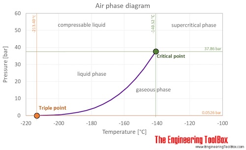


 Source:


 (scene from Hellboy 2)


 Source: