Thursday, 08:31, 24/08/2023
Well, morning.

By the time that I actually start making the exo/endo-skeleton, it will be buried under 3983932382 project logs.
... But I think this is relevant, because I need to talk about Dielectric Elastomers and I already wrote so much crap on the previous project logs about linear actuators that hackaday simply starts deleting new text on them.
Just to recaptulate:
The hydraulic artificial muscle system, although being lighter and allowing a higher efficiency, since it is lighter than metal hydraulic cylinders, its oil still weights a lot.
More or less 180kg to 225kg.
So I thought "hey, since I'm already facing such inneficiencies with such system, then why not try something else?"
Then I calculated pneumatics, but those are inneficient as heck and quite dangerous to work with.
Then I thought on Dielectric Elastomer Actuators, those wouldn't need an electric to mechanical to hydraulic conversion and make a somewhat efficient system, even if these aren't that efficient in the first place.
In any way, I was absolutely sure about the efficiency of dielectric elastomers to be really low, but after looking into some review papers of dieletric elastomers, I'm not so sure.
You see, for some reason, when I look at dielectric elastomers review papers (such as the one bellow), they always say that the efficiency of DEA's are around 80% to 90%.
https://onlinelibrary.wiley.com/doi/epdf/10.1002/aisy.202000282

... But when I "ask around" and/or search for specific articles with new DEA's, it is always something bellow 40% efficiency.
And the problem is: when I try to look into the bibliographic sources these review articles use, instead of leading me to specific studies, they send me to older review papers with the same efficiency reference and I can't find the actual production method.
Bro, I'm reading articles from the early 2000's and I still didn't find a single fricking method of production (or I simply didn't pay enough attention, I have ADHD after all).
The article in question:
https://link.springer.com/article/10.1557/PROC-600-119
You will need sci-hub to see it, but basically, it says it uses something related to acrylic.
In either way, there are 2 options here:
- Either I'm simply not reading the full information (since I'm literally fast scrolling though everything, that's my fault).
- Either some articles simply take references without double-checking their sources (which is doubtful).
- Either they are talking about dielectrict elastomer generators (that convert mechanical energy into electrical) instead of actuators.
A 4th option would be that the movement that the dielectric elastomer makes is highly efficient, but the elasticity of the material reduces the efficiency.
Most of the dielectric elastomers have a really low actuation, in the milimeters of actuation, so they need to make a reversebly actuated artificial muscle, just like the hydraulic ones I was thinking on making.
And thus, the necessity of making the muscle relax when voltage is on and contract when the voltage is off means a low efficiency of energy transmission.
Also, I thought on two ways of making dielectric elastomer artificial muscles systems.
Basically, I either do the reversebly actuated or the membrane actuated.
At more or less 2:11 time in the video, you can see how big it is the actuation of the membrane, if you were to pass a shaft/rope through the membrane and stacked a lof of these membranes, you could make an artificial muscle pull it up.
Something akin to this, but with a rope instead of a rigid shaft.
Now, the reversibly actuated you already know: you make a strand, when voltage is on, the strand relaxes, increasing length, and once the voltage is off, the strand contracts.
Or maybe neither of these, but continuum design (aka tentacles):
I posted it at the end of the previous Project Log about linear actuators, but here is the online article about the Acrylic Elastomer:
https://samueli.ucla.edu/wp-content/uploads/samueli/Compiled-PHDE-SI-Videos.mp4?_=1
(well, this was supposed to be a video, but it doesn't appear on hackaday)
https://www.science.org/doi/epdf/10.1126/science.abn0099


I'm just interested on this one in specific at the moment because ChatGPT suggested this one.
There are thousands of different Dielectric Elastomer articles around the internet and I need to find one that best suits my needs.
I don't know which method (membrane or strand) would be the best.
Plus, I need to actually read the goddang articles in order to find the easiest to make and the most efficient to use.
I tried to read a lot of articles and now I remember why I gave up with this idea before... It involves really complicated stuff (for my smooth brain) and chemicals that I simply can't directly buy on the internet.

One section of the previous article (that by the way, was the most clear and higher performance article that I found) says the following:
"A PHDE film was demonstrated to toss an aluminum ball, which is 20 times as heavy as itself, to 12.1 cm high (Fig. 2E and movie S3), reaching an energy transfer efficiency of ~10%(fig. S20)."
Well, I don't know if this is the energy transfer from the electric system to the elastic motion of the system that turns into knetic/mechanical energy on the throwing of the ball or if is the efficiency of electrical current being transformed into mechanical energy by the elastomer.
I asked ChaGPT to tell me the summary because I legitimaly couldn't find the answer:
"The processable, high-performance dielectric elastomer (PHDE) film discussed in the research paper is primarily composed of acrylate-based materials. The authors of the paper used a combination of specific acrylate monomers and cross-linkers to create the tailored elastomer network structure. The main components used in the PHDE film are butyl acrylate (BA), isobornyl acrylate (IBOA), urethane diacrylate (UDA), and propoxylated neopentyl glycol diacrylate (PNPDA), along with cophotoinitiators to enable curing under UV light.
In summary, the PHDE film is based on acrylate chemistry, and the specific combination of acrylate monomers and cross-linkers allows for the creation of the desired bimodal network structure with enhanced mechanical and electromechanical properties."
So they used a bunch of acrylic based polymers that I don't fricking know how to find on top of using "cophotoinitiators" or whatever lovecraftian name this sounds.
I can only find acrylic-poliurethane thinners, nothing closer to what I actually need.
I could make tests using conventional silicon rubber, latex rubber and/or polyurethane rubber, but I'm not very confident on the results.
In fact, I don't want to buy and test these things because I simply do not even understand the subject.
I guess I will have to work with either polyurethane (which is expensive) or liquid silicone rubber for this specific task.
Well, at least my time searching for copious amounts of silicone rubber weren't in vain I guess...
Welp, after looking for it for a while, I gave up on dielectric elastomers. It is really is something that I could only have a proper understanding of how much force and power each actuator applies if I were to build it and test it personally.
Which is beyond my technical (and brain) capabilities.
If you want to pursue this specific subject anyway, I will just let this chat with ChatGPT here:
-------------------------------------------------------------------------------------------------------------------------------------------
To increase the compatibility of silicone rubber for use as a dielectric elastomer actuator, various modifications and techniques can be employed to enhance its dielectric and mechanical properties. Dielectric elastomer actuators require materials with high dielectric constants, good electrical insulation, and mechanical flexibility. Here are some strategies to improve silicone rubber's suitability as a dielectric elastomer:
- Fillers and Nanocomposites: Incorporating high-permittivity fillers, such as ceramic nanoparticles (e.g., barium titanate), can increase the dielectric constant of silicone rubber. These fillers can enhance its electromechanical responsiveness to an external electric field.
- Cross-Linking and Curing: Proper cross-linking of the silicone polymer chains is crucial to achieve the desired mechanical strength and durability. Adjusting the curing process, temperature, and duration can optimize the cross-linking density and resulting properties.
- Silicone Blends: Blending silicone rubber with other polymers or elastomers can help achieve a balance between mechanical strength and dielectric performance. For instance, combining silicone with a high-strength elastomer can improve overall mechanical stability.
- Electrode Compatibility: Enhancing the compatibility between silicone rubber and compliant electrodes is vital to ensure good adhesion and electrical performance. Surface treatments or primers can be applied to improve electrode adhesion.
- Plasticizers: Introducing compatible plasticizers into the silicone rubber matrix can enhance its flexibility and stretchability, which are crucial for actuation. However, careful selection is required to prevent plasticizer leaching and maintain stability.
- Surface Modification: Treating the surface of the silicone rubber with plasma or chemical processes can alter its surface energy and enhance its adhesion to other materials, such as compliant electrodes or additional layers.
- Layered Structures: Designing multilayer structures with different materials can provide enhanced performance. For example, incorporating a high-strength layer alongside the silicone dielectric layer can improve mechanical stability.
- Temperature Stability: Silicone rubber's performance can be affected by temperature variations. Formulating the material to have improved thermal stability and reduced temperature-dependent changes in mechanical and dielectric properties can be beneficial.
- Processing Techniques: Utilizing advanced processing techniques, such as melt blending, solution casting, or extrusion, can help achieve better dispersion of additives and fillers, leading to improved overall properties.
- Thinning Strategies: Thinning the silicone rubber material while maintaining its dielectric properties can increase its responsiveness to electric fields, enabling higher actuation strains.
Remember that the modification process should be guided by a comprehensive understanding of the material's properties, the specific requirements of the application, and the trade-offs between dielectric performance and mechanical stability. Testing and optimization are crucial to achieve the desired combination of properties for silicone rubber-based dielectric elastomer actuators.
Certainly, here's a list of materials in each category that I mentioned earlier:
High-Permittivity Fillers:
- Barium titanate
- Titanium dioxide
- Zirconium oxide
- Strontium titanate
- Lead zirconate titanate (PZT)
Cross-Linking and Curing Agents:
- Platinum-catalyzed silicone curing agents
- Peroxide curing agents (for addition-cure silicone)
Silicone Blends:
- Silicone/Thermoplastic elastomer blends
- Silicone/Polycarbonate blends
- Silicone/Acrylonitrile Butadiene Rubber (NBR) blends
Surface Treatments:
- Plasma treatment
- Silane coupling agents (e.g., silane primers)
- Corona discharge treatment
Plasticizers:
- Dioctyl phthalate (DOP)
- Dioctyl adipate (DOA)
- Dimethylsiloxane-based plasticizers
Layered Structures:
- Silicone layer combined with thermoplastic layer
- Silicone layer on top of fabric reinforcement
Temperature Stability Enhancers:
- Heat-resistant additives
- Inorganic fillers for improved thermal stability
Processing Techniques:
- Melt blending
- Solution casting
- Extrusion
Please note that the selection of specific materials from these categories will depend on the desired properties and application requirements. Additionally, the use of some materials may vary based on factors such as regional regulations and advancements in material science. Always ensure to refer to the most up-to-date literature and resources when making material choices.
I searched for (a lot of) silicone dielectric elastomer articles and all of the suggestions ChatGPT gave kinda checks out.
-------------------------------------------------------------------------------------------------------------------------------------------
While stumbling my way through unnecessarily exotic actuators to fulfill my endless curiosity, I found something called "MagnetoRheological elastomers" (or Magnetoactive elastomers), which, if you readed all my project logs may be familiar with.
Basically, it is just a rubber material with magnetic powder (like iron) on it, and it is used in a similar way as dieletric elastomers.
Le problem is that it needs magnetic coils to work.


Maybe you could make a coiled/braided magnetorheological fiber and put it inside of a long copper coil, forcing the braided magnetic polymer to follow the coiled path.
But again, maybe.
I don't know the efficiency of such system or how practical it would be to make it myself.
-------------------------------------------------------------------------------------------------------------------------------------------
By the way, while I was searching for the subject of dielectric elastomers, I also stumbled upon shape memory alloys, and one thing that I saw that I thought it was quite interesting was microwave activated shape memory alloys.
Well, unfortunately, microwave magnetrons (the part responsible to convert electricty into microwaves) are quite bulky, heavy and dangerous.
A possible solution I would suggest would use micro magnetrons and/or microwave antenna emissors. Although I doubt it would be as cheap or smaller.
I just found this instructables teaching about microwaves, and it says:
"Lower power microwaves can me produced by some solid state devices such as the FET (field effect transistor), the tunnel diode, the gunn diode, and the IMPATT diode."
Although the parts that he mentioned aren't that cheap either, it is a little bit cheaper and lighter than a fricking magnetron.
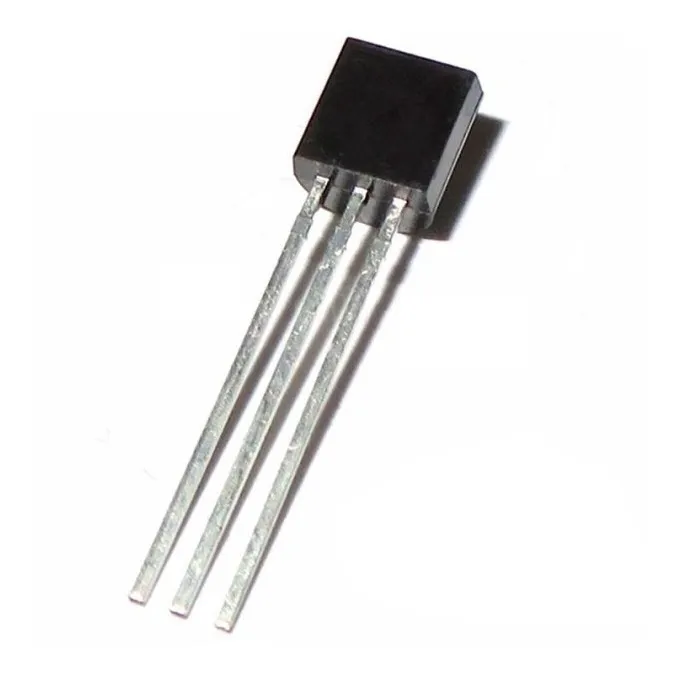
I found some fet mosfet like the ones in the image on google shopping, but I don't know if this little thing would produce enough microwaves to heat artificial muscles.
(But after asking to ChatGPT, it seems like you wouldn't need microwaves at all, silicon carbide is good conversor of electricity to heat)
Another possibility is using DIY conductive ink but instead, adding silicon carbide, since it transforms microwaves into heat more efficiently.
Silicon carbide is so good in converting microwaves into heat that it is used into microwave furnaces/kilns.
This method would also work with nylon/polyethylene artificial muscles instead of using nichrome or kanthal heating wire.
You can also electroplate it, although I don't know why you would go over such trouble if graphite and/or silicon carbide are already very resistive, meaning it would turn electricity into heat more efficiently than highly conductive nickel/copper/zinc.
Speaking of Shape Memory Alloys, here are other SMA's that aren't nickel-titanium (nitinol):
(by the way, nitinol is made by melting nickel and titanium in a vacuum either by electromagnetism or ark furnace over a water cooled copper table, thus the price)
"There are several other alloys besides Nitinol (Nickel Titanium) that exhibit shape memory alloy (SMA) behavior. These alloys are known for their ability to "remember" a specific shape and return to that shape when subjected to certain temperature changes or mechanical stress. Here are a few examples:
- Copper-Aluminum-Nickel Alloys (Cu-Al-Ni): These alloys are often referred to as "Copper-Based Shape Memory Alloys." They exhibit shape memory behavior due to a reversible martensitic transformation. They are used in various applications, including medical devices and actuators.
- Copper-Zinc-Aluminum Alloys (Cu-Zn-Al): Another type of copper-based SMA, these alloys have a similar transformation mechanism to Cu-Al-Ni alloys. They are utilized in applications such as eyeglass frames and thermal actuators.
- Iron-Manganese-Silicon Alloys (Fe-Mn-Si): These alloys are known for their high-temperature shape memory behavior. They can recover their original shape after being deformed even at elevated temperatures. Applications include high-temperature actuators and sensors.
- Copper-Zinc-X Alloys (Cu-Zn-X, where X can be Aluminum, Tin, or other elements): These alloys are part of the copper-zinc family and exhibit shape memory behavior due to a reversible transformation between austenite and martensite phases. They are used in various engineering applications.
- Iron-Platinum Alloys (Fe-Pt): These alloys exhibit shape memory behavior at very low temperatures. They are being studied for applications in areas like cryogenic engineering and aerospace.
- Nickel-Gallium (Ni-Ga) Alloys: These alloys show shape memory behavior in response to magnetic fields rather than temperature changes. They are used in sensors, actuators, and various magnetically controlled devices.
- Copper-Gold-Aluminum Alloys (Cu-Au-Al): These alloys have a two-way shape memory effect, which means they can recover two different shapes upon heating and cooling. They find applications in microactuators and medical devices.
- Titanium-Niobium Alloys (Ti-Nb): These alloys exhibit shape memory behavior in response to stress-induced martensitic transformation. They are utilized in applications where high mechanical damping and superelasticity are required.
These are just a few examples of shape memory alloys with various compositions and properties. The field of shape memory alloys is continuously evolving, and researchers are exploring new compositions and applications for these unique materials."
4.2. Cu-based SMAs
Cu based SMAs though not having supreme shape memory properties like Ni–Ti alloys, are exploited for their modest shape memory properties (superior to Fe based systems), cheaper production cost and ease of fabrication [46]. They are considered as cost effective because they are easily produced using conventional liquid metallurgy and powder metallurgy routes utilized for processing traditional Cu based alloys [8]. Also, they do not have high reactivity levels which necessitates special furnace environmental conditions during melting as in the case with processing of NiTi [8]. In addition the Cu based alloys have a wide transformation temperature range, a large superelastic effect, small hysteresis and high damping coefficient. All of these desirable properties have widened the potentials of Cu based in shape memory applications where the NiTi alloy is currently explored.
Source: https://www.sciencedirect.com/science/article/pii/S2215098616301070#f0010
"Sure, here's a list of some shape memory polymers (SMPs) along with their efficiency, stroke length, and material content:
- Polyurethane-based SMPs:
- Efficiency: High
- Stroke Length: Medium
- Material Content: Polyurethane-based polymers
- Polyethylene-based SMPs:
- Efficiency: Low
- Stroke Length: Short
- Material Content: Polyethylene-based polymers
- Polycaprolactone (PCL) SMPs:
- Efficiency: Medium
- Stroke Length: Long
- Material Content: Polycaprolactone polymers
- Polyethylene terephthalate (PET) SMPs:
- Efficiency: Medium
- Stroke Length: Medium
- Material Content: PET-based polymers
- Polylactic acid (PLA) SMPs:
- Efficiency: High
- Stroke Length: Short
- Material Content: Polylactic acid polymers
- Polyvinyl alcohol (PVA) SMPs:
- Efficiency: Medium
- Stroke Length: Long
- Material Content: Polyvinyl alcohol polymers
- Polyacrylamide-based SMPs:
- Efficiency: Low
- Stroke Length: Short
- Material Content: Polyacrylamide-based polymers
- Poly(ε-caprolactone-co-trimethylene carbonate) SMPs:
- Efficiency: High
- Stroke Length: Long
- Material Content: Copolymer of ε-caprolactone and trimethylene carbonate
- Poly(propylene fumarate) SMPs:
- Efficiency: Medium
- Stroke Length: Medium
- Material Content: Poly(propylene fumarate) polymers
- Poly(n-isopropylacrylamide) SMPs:
- Efficiency: High
- Stroke Length: Short
- Material Content: Poly(n-isopropylacrylamide) polymers
Please note that the efficiency, stroke length, and material content can vary depending on the specific formulation, processing methods, and application requirements. The terms "efficiency" and "stroke length" might also have different interpretations based on the context of the shape memory application. This list provides a general overview of some commonly used shape memory polymers and their properties."
Well, this looks interesting.
The ones that I was able to find besides its lovecraftian names and interesting properties were: Polyurethane, Polyethylene, Polycaprolactone (PCL) and Polyvinyl alcohol (PVA).
"Certainly, here's a list of materials and methods commonly used in the production of Polyurethane, Polyethylene, Polycaprolactone (PCL), and Polyvinyl Alcohol (PVA) based shape memory polymers:
Polyurethane-based SMPs: Materials:
- Diisocyanates (e.g., MDI, TDI)
- Polyols (e.g., polyester polyols, polyether polyols)
- Chain extenders (e.g., butanediol)
- Catalysts
- Crosslinking agents
- Chain regulators
- Fillers (optional)
- Solvents (for processing)
Methods:
- Solution Casting:
- Diisocyanate, polyol, and other additives are dissolved in a solvent.
- The solution is cast into a mold or on a substrate.
- Solvent is evaporated to form the polymer.
- Thermoplastic Processing:
- Diisocyanate, polyol, and other additives are melted and mixed.
- The melt is shaped using techniques like extrusion, injection molding, or compression molding.
- Cooling solidifies the polymer into the desired shape.
Polyethylene-based SMPs: Materials:
- Polyethylene resins (various densities)
- Crosslinking agents (e.g., peroxides)
- Fillers (e.g., nanoparticles, fibers)
- Additives (e.g., stabilizers, pigments)
Methods:
- Crosslinking through Irradiation:
- Polyethylene is exposed to ionizing radiation (gamma, electron beam).
- Crosslinking agents promote crosslinks between polymer chains.
- Thermal Crosslinking:
- Polyethylene is mixed with crosslinking agents.
- Elevated temperatures initiate crosslinking reactions.
Polycaprolactone (PCL) SMPs: Materials:
- Polycaprolactone (PCL) polymer
- Crosslinking agents (e.g., diisocyanates)
- Initiators or catalysts
- Fillers (optional)
- Solvents (for processing, if needed)
Methods:
- Chemical Crosslinking:
- PCL is mixed with crosslinking agents and initiators.
- Crosslinking reaction is triggered by heat or other stimuli.
- Thermoplastic Processing:
- PCL is melted and shaped through methods like extrusion or compression molding.
- Shape fixation can be achieved by cooling or through crosslinking.
Polyvinyl Alcohol (PVA) based SMPs: Materials:
- Polyvinyl Alcohol (PVA)
- Crosslinking agents (e.g., glutaraldehyde)
- Plasticizers (e.g., glycerol)
- Initiators (for photo-crosslinking)
- Fillers (optional)
- Solvents (for processing)
Methods:
- Chemical Crosslinking:
- PVA is mixed with crosslinking agents and initiators.
- Crosslinking is induced through chemical reactions (e.g., crosslinking agents or heat).
- Physical Crosslinking (Physical Hydrogels):
- PVA chains are physically crosslinked through methods like freeze-thaw cycles or crystallization.
- Photo-Crosslinking:
- PVA is mixed with photo-initiators.
- Crosslinking is initiated by exposure to UV or visible light.
Please note that the specific methods and materials used can vary based on the desired properties of the shape memory polymers and the intended applications.
The only one that I was able to find materials to buy was PVA based Shape Memory Polymers...
Well, PVA by itself is already shape memory polymer, but I don't quite like the speed in which it moves.
Although you could just add silicon carbide and/or graphite to the mix in order to make it heat faster, you still is limited by the heat limit of the material, which is not a concern with Nitinol wires.
Besides, I didn't yet finish studying about the subject, maybe these are faster.
Well, I actually tried to read a ton of articles on the subject, and just like silonce rubber based dieletric elastomers, each article focuses on an specific function, method and characterization of the polymer instead of a general function of being used as an actuator.
And thus, I can't find enough information in order to understand and/or predict the properties of the shape memory polymer in order to be used as an actuator.
And thus, this project log was just a waste of time...
At this point I was even considering magnetic coils actuators.
Not voice coils or anything like that, magnetic coils.
When there is a big enough electric current passing through copper coils, they "contract" simply because the magnetic field becomes so strong it makes the coils compress.
I can't fing the goddamn video again, but a guy did that.
However, I don't know at which voltage and current he did that and neither I know how efficient it is or would be.
Found it.
It is at such high amperage the coil literally burns.
Dunno if it would work with the magnetorheological rubber inside the coils on concentric tubes with everything submerged in insulating oil for cooling.
But to me it seems an interesting actuator, but I don't really want to deal with 100+ amps just for a funny copper coil.
I don't even know how many grams of force this little thing can even output.
Also, this video is linked at the end of the previous video, kinda relevant since Lorentz Force is strong enough to move heavy wires.
Actually, I was even considering flexible voice coil actuators, but even then, I don't think I have enough knowledge on the subject even to attempt something like this...
In fact, I'm still not fully aware of how voice coils work, but I do know those are expensive and meant for really low force ultra high precision actuations.
(I mean, technically the previous idea would be a flexible voice coil actuator)
In either case, I just asked around on multiple websites, but I doubt anyone would give a serious look a this.
Also, I was thinking of making this like a "reverse electrostatic" actuator, in the sense that electrostatic comes in kilovolts (thousands of volts) but with an incredible low amperage (aka current) in the microamps (0.000001 amps), so a reverse electrostatic would have kiloamps and microvolts instead.
I asked around and dude, asking help on the internet is kinda tough.
People either know as little as myself and wish they could help more, or simply tell me to f8ck myself and stop waisting their time (which unfortunately is the one that happens the most).
In either way, I receive two interesting suggestions. These two websites show a lorentz force calculation, which I can't make heads out of. But I tried a little bit.:
https://danielteodesigntechnology.wordpress.com/theoretical/supplement-lorentz-force-actuation/
"An Electromagnetic (EM) scheme realized through a Lorentz-force principle requires an air-core coil where presence of current is only used to generate force. If the coil is wound around a ferrous material core and generates a magnetic field to propel a permanent magnet, it will be another form of EM scheme, termed Attraction/Repulsion, commonly found in solenoid actuator."
Field coil, d = 120 mm
In the second I don't know if the "field coil" is the electromagnetic field generated by the coil, the coil diameter or the coil length.
If it is the coil diameter, a 12cm diameter coil will give" F/I = 0.138 mN/A" accordingly to the link, which is milinewtons per amp (1 milinewton = 0.001 newtons)...
I wonder if its force would increase proportionally accordingly if you were to decrease the coil diameter by 10 to 25 times, with a coil with 12mm of diameter and 5mm of diameter.
Would the force be 1.38 mN/a and 3.45 milinewton per amp respectively?
This means that I would need 1000x more amps to convert 0,00138 newtons to 1 newton or 300 times more amps to convert the 0.00345 newtons into 1 newton.
So, it would be either 5000 amps or 1500 amps.
I asked ChatGPT what force would the lorentz force apply in newtons to a coil with 5mm of diameter and 18 AWG (+/- 1mm of diameter), 1500 amps and 0.06 volts (90 watts), it said it would be applying 40 to 70 newtons of force (in some other answers, it says I would have 200 newtons of force).
And as you guessed it, it changes answer everytime I hit the "regenerate answer" button. So this value may be completly incorrect.
Plus, it didn't calculate the heat generation.
But in any way, you can see that the system is incredibly inneficient, after all, it took 90 watts (1500x0.06=90) to lift only 7kg.
It will definitely be tough to make a 5mm diameter copper coil and continiously cool it.
Maybe one could make a more resilient insulating layer by using sodium silicate instead?
Maybe² the heating issue could be solved if you activated and disactivated the current very fast?
Maybe³ by increasing the number of coils receiving the current, the area will increase, the heat inneficiency will decrease and the efficiency with the magnetic field will increase.
It also makes me wonder if it would be possible to make a soft magnetic composite core and "contract" the length of both the coil and the core using both the lorentz force and the magnetic field. But like it was said in the first link: if you add a core it won't be a lorentz force actuator anymore, it will act like a solenoid.
So many questions... And I'm too dumb to answer any of them.
The closest I could find was this article: https://www.semanticscholar.org/paper/Prototyping-the-flexible-solenoid-coil-artificial-Takai-Alanizi/e2ce146b51b584ce50410afb4ef1590269fe0908
It uses a rigid articulated solenoid coil in order to act like a muscle.
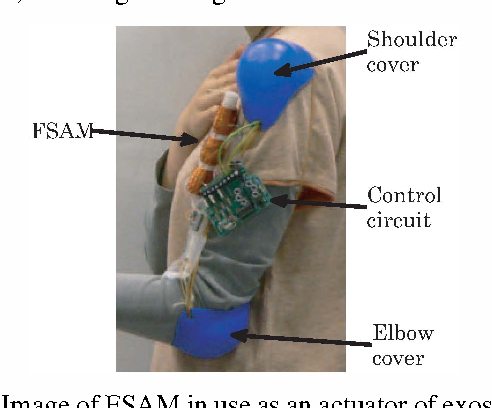
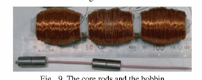
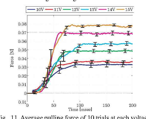
It produces 0.08 newtons at 15 volts, hum...
---------------------------------------------------------------------------------------------------------------------------------------------
I don't know if I'm not trying enough, or if I'm genuinely facing a problem so big even professionals would struggle.
In either way:
I'm writting this here since I don't have space on the previous project log, but I think I got an idea to solve the weight problem of the hydraulic artificial muscles.
One would be to instert a filler and occupy at least half of its length, reducing the weight from 225kg or 180kg (depending on the density of hydraulic oil you use) to 112.5kg to 90kg.
Then you could reduce by half even more if you filled opposite muscles only to 56.25kg to 45kg
Example: you actuate only half of the muscles at one moment, but once this half is relaxed, it will actuate the other half automatically.
Well, I don't quite like this idea simply because you would have all muscles under some tension and may result on muscles not receiving enough fluid if I'm not careful with the design...
Now I feel stupid.
Couldn't I do the same towards air?
I mean, it is clear from the start that pneumatic systems need careful opposition control since they simply expand.
Couldn't I "just" keep the entire system pressurized at 5 to 6 bar and simply pump the air towards the opposite muscles?
... But you would need to be very careful with leakages, which is a hell of a time to deal with in the case of pneumatic muscles...
I don't really think that there is a way out of the hydraulic weight problem...
---------------------------------------------------------------------------------------------------------------------------------------------
Since I can't add text to the previous project logs about linear actuators, I would like to list some ideas:
Basically, there are tubular plastic coils/bobbins that don't have divisions inside of it. Basically, a super long tube.
These come in meters and/or in kg and are somewhat cheap and can be found in a myriad of different shapes and types of materials.
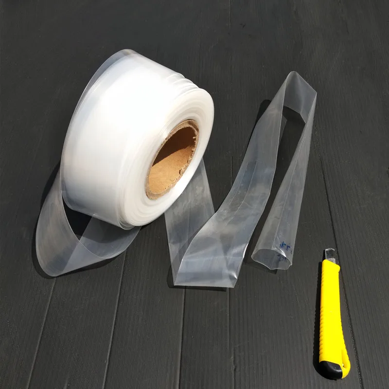
This is a Polyethylene transparent plastic.
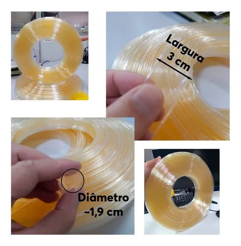
And this one is a PVC transparent tubular plastic with 3cm of flat length and diameter of 1.9cm and I found in a brazilian website costing 100 reais (20 dollars) for 2kg or 117 meters of length.
There are other websites that sell more kg for the same price using different plastics (PVC is heavier), but you got the idea.
Maybe you could use it for the filament McKIbben hydraulic muscle and/or the reversibly actuated hydraulic muscle with steel springs.
---------------------------------------------------------------------------------------------------------------------------------------------
Well, even though I talk so much about efficiency, I didn't check the efficiency of the entire system (maybe because I didn't even plan the system in the first place).
So, let's say we have that 60kg solid state hydrogen fuel cell I talked about in the previous project log + 10kg of latex rubber actuators + 45kg hydraulic oil + maybe a 100kg exo/endoskeleton = 214kg.
Assuming the efficiency of the 60kg battery is 60%, the efficiency of the electric motor is 90%, the efficiency of the pump is 88% and the efficiency of the hydraulic actuator is 60% and I want the equivalent of 300watts to go pass through all of this, I would have... 85.5 watts at the end of the thing, meaning that I would need 3.5 times more power in order to compensate for the energy loss.
I thought that maybe the battery is not worth the trouble of extracting the percentage of power because it will provide the required power indepently of its efficiency of extracting power from its materials.
Basically, it is the "origin" of the power, not the passage, so to speak (although it is a passage of power from the baterry charging [you get the drift]).
The new value would be 142.56 watts at the end, meaning that I would need more or less 2.1 times more power to compensate.
So, assuming that I use 600 watts of power for the 30 muscle groups, I would need around 18,000 watts (of course, assuming every muscle uses the same amount of energy, which is not the case), so, a maximum of 24 horsepower (if all muscles contract at same time, again, not the case).
... But, if you include the weight of the mech/exosuit, in the meaning that it is wasting energy carrying its own weight instead of doing useful work, then it would be wasting 1/5 of its 1000kg rating, in order words, wasting 20% of its efficiency.
So, the final result would be 114.048 watts, more or less 1/3 of the initial energy value. So you would need to insert 3 times the initial energy.
So the final result would be 900 watts maximum for every 30 muscle groups, giving 27,000 watts or 36 horsepower.
Again, not every bundle will be using 900 watts, and not all 900 watts muscles will be contracting at same time. A generic value would be around 8100 watts in total or 10.8 horsepower.
If someone were to make a system with 90% of efficiency in every step with as few steps as possible, you could reduce the energy cost by half.
But there is the problem of cost, manufacturing etc, so you can't just put 30 electric motors everywere.
Which makes me wonder if I'm not forgetting something.
For example, I was needing 9000 watts with the full electric motors, this means that I'm severely misscalculating something or creating energy out of thin air.
I don't know the actual reason, but basically, I reached the conclusion of 9000 watts by insterting the distance of actuation and speed on online calculators:
https://www.omnicalculator.com/physics/torque
Assuming the distance is 5cm and a weight with 3000kg (or 30 kilonewtons), accordingly to the calculator, I would need 1500Nm of torque.
https://www.omnicalculator.com/conversion/torque-to-horsepower
If I insert the torque of 1500Nm and the speed of 60 RPM, then I achieve a maximum power of 9500 watts (12 horsepower).
But since it has 3 of these on the legs, then I would require 36 horsepower in total.
Since the torso and arms are using 1/3 of that, then it would be 60 horsepower in total, or 45,000 watts.
But the hydraulic pump needs around 300 watts to move it in a pressure of 5 bar and a fluid flow of around 50 to 70 liters per minute, and it is enough to supply 375 muscles with 80 newton of force each, which gives around 30,000 newtons of force (3,000 kg).
The math checks out in both cases, but I don't know what is the deal tho...
I misscalculated the artificial muscles.

How did I... Calculated that the muscles would need 0.021 liters per minute...?

I was checking the Project Log 67 and there is a part where I say this:
"Assuming that the initial length is 15cm and the elongated state is 30cm, I would need to move around 0.001 liters, or 0.737 ml"
This should be a red flag from the start.
How did I get 0.001 liters from a tube with 12.5mm of diameter and 15cm of length which resulted in an elogation of 30cm?
I think I know how, I simply made the mistake of changing the Centimeter to Milimiter without noticing.

In the case of the RAHAM (reversibly actuacted hydraulic artificial muscle), if I were to have a 15cm long muscle with 12.5mm of inner diameter, I would have 0.018 liters, since I were to double this value with the elongation to 30cm, I would need to pump 0.018 liters. I mean, duh.
So, 0.018 x 5 x 60 = 5.4 liters per minute of fluid flow.
The 5 there is that the muscle will need to contract in 1/5 of a second in order to make the limb move in a speed of 30 RPM.
If I wanted to elongate 300 muscles for the 3 ton value, I would need 1620 liters per minute of fluid flow.
If I had hydraulic pumps using 900 watts of power to pump 50 to 70 liters per minute, I would need 23 pumps using 20,828 watts of power in total. Or 27 horsepower.


If you read the description of the project, I wrote:
"I will try to list in this project here all the ideas I had/have because I'm noticing that I'm repeating the same cycle of ideas"
How I can make the same mistake again and again throghout 70+ project logs?!
Just how?
Can I not make a math mistake for 5 MINUTES?!

At best, you could use the artificial muscles for the 100kg rated exoskeleton and use the values previously noted here.
Basically:
A muscle with 1 inch in inner diameter + 30cm of length has 0.152 liters of volume and contracts to 40mm of inner diameter and 18cm of length, having 0.226 liters.
The actuation needed 0.074 liters.
0.074 liters x 5 x 60 seconds x 3 actuators to pull 300kg in total = 66 liters per minute, or more or less 900 watts.
The legs would need 3 times that value either in pressure or in fluid flow, so in total:
900 for the arms + 900 for the torso + 2700 of the legs = 4500 watts or 6 horsepower.
Plus, you would need the other half of the body that would also use more or less half of the energy, totalizing 9 horsepower or 6750 watts per hour.
Although these numbers look decent, if you were to increase the force 10 times to achieve the 1 ton force, you would be using 90 horsepower.
Being honest, I don't even know if the value of 900 watts is correct anymore.
See, the electric motor will be inputing 360 watts (to compensate for the 88% efficiency) and the pump will be inputing 300 watts, but the muscle will actuate with 5 bar of pressure and 22 liters per minute, outputing 100kg of strength.
So... I will actually need around 1/3 of what I previously thought? 2 to 20 horsepower?
So this means it is viable?
... And that the electric version still consumes more power?

I seriously need the help of an engineer...
Just checking on other hydraulic pumps, I would need around 10.3kilowatt (13.8hp) for 200 bar of pressure and 3000 rpm (I'm talking about the one with 14 ml/r on the thing below).
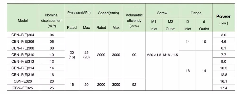
Since I need 3000 rpm and 5 bar instead of 200 bar (20 MPa), this would be more or less 40 times less torque, so 34.376 Newton Meter/40 = 0.8594, 3000 RPM + 0.8594 Nm = 270 watts. :|
Even less power than before...
This would also mean that I would need 2700 watts (3.6 horsepower) for each 1000kg muscle.
By the way, here is the link for the mentioned hydraulic pump:
https://aliexpress.com/item/32993498984.html
(You buy it on your own risk, I'm just linking it here for reference)
---------------------------------------------------------------------------------------------------------------------------------------------
Although it would be nice to only consume 2 horsepower for a single exoskeleton, It would be a pain in the butt to make 30+ pumps and buy 30+ electric motors to power them.
I think it would be the best if I were to take a single 100L/min rated pump, make it 6 times longer and fulfill the 600 liters per minute of fluid flow that all muscles would required to be activated at same time (or just half of it).
A single pump would need around 1 horsepower to pump 100 liters at 2500 rpm and 3 Nm of torque, so in total it would consume 6 horsepower in total (or 3 if you only take half).
Of course, if it would be to a 100kg rated exosuit, for a 1000kg rated it would take 10 times more energy to pump enough fluid.
The pump will activate a big hydraulic accumulator that in turn could be mechanically or electronically controlled to liberate fluid to the desired muscle through the preferred activation system (mechanical, using pinch valves or electronic by solenoid/servo valves).
Or you could make a single pump for every limb and and have 5 hydraulic accumulators in total.
Yes I will try to make a project log for the hydraulic accumulator and valves, but I think I will put it under the Hydraulic Pump section.
One thing that I forgot to talk: you need to put more energy on the hydraulic accumulator in order for it to work.
So in order to have a hydraulic accumulator that outputs 5 bar of pressure, I need to input 9 to 10 bar of pressure in order to charge it, already losing 50% of the input energy.
It may not be the best option, after all.
I think I already talked about this detail before...
---------------------------------------------------------------------------------------------------------------------------------------------
Well, there is so much text on this project log that this part is probably going to be deleted, but whatever.
I was thinking here that the best linear actuator is not the artificial muscles, but that flexible hydraulic cylinder.
Although I don't know how one would turn that hydraulic cylinder flexible, you can just use a conventional cylinder with a cable attached to the cylinder head.
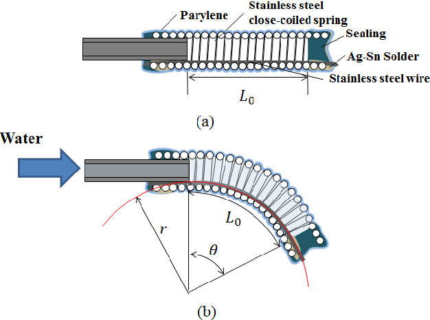
I say this because hydraulic cylinders are 95% efficient, while McKibben muscles are 60% efficient, but since this "pulling hydraulic cylinder" could be made out of plastic with the same 5 bars of pressure, you would be using the best of both worlds.
Again, it wouldn't be flexible and to be honest, I don't know how you could make it flexible and being able to withstand the pressure inside of it without expanding the entire actuator.
The second article show that the bending hydraulic actuator was able to withstand up to 1000 KPa (10 bar) of pressure, while I only plan on applying 500 KPa (5 bar) of pressure.
The thing is: would that be appliable to an actuator meant to lift 10 to 100kg?
Plus, the actuator is meant do coil like a tentacle.
By the way, you would need a inner diameter/piston diameter of 15mm to reach 10kg of force at 5 bar of pressure or 50mm to reach 100kg at 5 bar of pressure.
However, depending on the cable, which occupies space, the final force may be lower.
PVC tubes can withstand pressures up to 7 bar of pressure, but I don't know if this would be enough to lift 100kg...
By the way, I found that normal reinforced garden irrigation hoses can withstand pressures up to 20 bar and are still flexible.
One could use these hoses as this flexible pulling hydraulic actuator.
---------------------------------------------------------------------------------------------------------------------------------------------
By the way, just now this guy posted this interesting linear actuator:
It is just like those rotary to linear motion actuators, but instead of a crankshaft, it is a chain drive that allows for longer actuations.
Although the only problem I have with it is that sliding square thingie, even though I don't know what could be used to replace it...
As far as I can remember, motorcycle chains can withstand up to 200kg of force, so you would need at least 5 of these for a 1 ton load or 15 of these in parallel for a 3 ton load.
Assuming that there aren't conventional sprockets/chain-drives that can withstand these kinds of loads...
Discussions
Become a Hackaday.io Member
Create an account to leave a comment. Already have an account? Log In.
just make a gmo living suit
Are you sure? yes | no
Nah, I want a mech
Are you sure? yes | no
but you could have moist mech?
Are you sure? yes | no