Mark VandeWettering
-
Code uploaded to github
01/02/2017 at 02:02 • 0 commentsI've been busy with my other 1K challenge entry, and haven't had much time to get back to work on the 1Keyer. It's been somewhat hampered by the fact that I was missing some hardware from my iambic key. I looked up the documentation for it, and it said I needed a pair of 4-40 9/16" cap screws. I ended up having to order them from McMaster-Carr. But annoyingly, these screws seem to be a bit short. I suspect that 11/16" are actually appropriate. Not sure I'll get any new ones before the 5th deadline.
So, instead I soldered some leads on a pair of push button switches and used them for debugging. They were sufficient to allow me to test the code, and after a few tweaks, it appears that all is working as designed. Trying to send letters via these two buttons is a bit error prone though, and I'm not sure that the state machine handles delays between characters in the most intuitive way.
I'll try to demonstrate the functionality in a YouTube video in the next day or two.
-
Oh say can you 'C'?
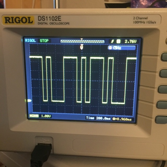
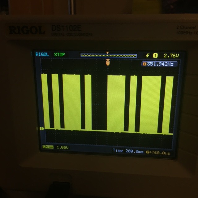
12/14/2016 at 03:13 • 0 commentsNot much of an update, except that I got the first characters keyed from 1Keyer prototype. Here are two quick iPhone pics of it transmitting a repeat of the 'C' character (dah dit dah dit). The first is a scope trace of the keying output (normally would go to a BJT or an optoisolator) and the second is the sidetone output (which is generating a 700Hz square wave) that can be used as an audio indicator of the operation of the keyer.
Right now, I'm about 60 bytes over on total space used, and there were a few more features I wanted to add, and I haven't even really debugged all the features yet. 1K might still be challenging. I'd rather not resort to a lot of assembler tricks, but darn it, I will make it fit!
![]()
![]()
-
Tone generation using PWM
12/12/2016 at 07:11 • 0 commentsThe last piece of code I needed to write for this project was code to generate a 700Hz tone on command. There are a number of was I could do this, but I chose to use Timer1 in CTC (Clear Timer on Compare) mode.
The code isn't actually very complicated (quite tiny, in fact.) It mostly configures the Timer, and then enables an interrupt. Every 64 clock cycles, the timer counter register increments. When it reaches OCR1A, it triggers an interrupt, and the clock is reset to zero. We want to generate a 700Hz signal, which means that we need to generate flip from high to low at twice that rate. On each interrupt, we flip from high to low, and then back again.
I coded this up to toggle the LED pin (13) on the Arduino. It worked the very first time I coded it up. When I hooked up my Rigol oscilloscope, it showed a nice 701Hz square wave. It will be pretty easy to toggle it on and off (basically just set the TIMSK1 value to enable and disable the interrupt.
Over the next couple of days, I'll get all this code integrated together, and see if it really will work in just 1K. I'm optimistic.
#include <stdio.h> #include <avr/io.h> #include <avr/interrupt.h> // For my 1Keyer program, I wanted to generate a 700hz square wave // on an auxillary pin, so I could use it as a "sidetone". The // easiest way would seem to use "CTC" (Clear Timer Compare) mode. ISR(TIMER1_COMPA_vect) { // Every time we execute this interrupt, we are going // to toggle the value of the output pin. PORTB ^= _BV(5) ; } #define CLOCK_PRESCALER 64 #define FREQ 700 #define OVERFLOW_COUNT (((F_CPU/CLOCK_PRESCALER)/(2*FREQ))-1) int main() { // LED is on PB5, so configure it for output... DDRB |= _BV(5) ; // And set it high. PORTB |= _BV(5) ; TCCR1A = 0 ; // CTC mode, clock divide by 64... TCCR1B = _BV(WGM12) | _BV(CS11) | _BV(CS10) ; OCR1A = OVERFLOW_COUNT ; // Turn on the overflow interrupt... TIMSK1 |= _BV(OCIE1A) ; sei() ; // Turn on interrupts, and the pin will chug away // at 700Hz. for (;;) ; } -
We Interrupt This Program...
12/11/2016 at 19:01 • 0 commentsIn one of my earlier project logs, I noted that the Arduino framework was a little bit annoying because it basically hides all the details having to do with interrupts from you, and that interrupts are powerful. If we look at the disassembled version of an Arduino sketch that does serial I/O, you will find that a lot of space is dedicated to the routines which handle the Serial object and the assorted Print helper functions.
For the 1Keyer, we want to be compact, minimal and efficient. Essentially all our input and output will consist of single characters, so all we really need is just some single I/O routines. But some degree of buffering is probably a good idea: I can easily type around 20WPM which is on the high side for most people's Morse code skills, and it isn't hard to bust out at 30WPM or 40WPM. If your keyed is set to 12 or even 5 WPM, you will easily get way ahead, and some buffering is a good idea.
Luckily, by virtue of the fact that we are using an Arduino module which has the ATmega328, we have about 2K of static RAM, of which we have used very little, and can dedicate it almost entirely for a keyboard type ahead buffer.
We could do (and still might do some) polled I/O...
First of all, we should note that it's not tremendously hard to do single character polled I/O without invoking the Serial object (and incurring all their cost). Mika Tuupola wrote a nice little tutorial that will explain most of the details, and some of the setup is the same even if we choose to with interrupts, so it's worth talking about.
The bare bones initialization code looks something (well, exactly like this, I swiped it from his tutorial):
#define F_CPU 16000000UL
#define BAUD 9600

#include <util/setbaud.h>

void uart_init(void) {
    UBRR0H = UBRRH_VALUE;
    UBRR0L = UBRRL_VALUE;

#if USE_2X
    UCSR0A |= _BV(U2X0);
#else
    UCSR0A &= ~(_BV(U2X0));
#endif

    UCSR0C = _BV(UCSZ01) | _BV(UCSZ00); /* 8-bit data */
    UCSR0B = _BV(RXEN0) | _BV(TXEN0);   /* Enable RX and TX */
}
Basically the first line defines the frequency at which the CPU operates. For a classic Arduino that operates at 5 volts, that is typically 16MHz. If you chose a 3.3V variant, they are commonly set at 8MHz. If you are using platform and specify a particular sort of Arduino, it knows what frequency you are after and provides this define for you.
Second is your choice of baud rate. 9600 is pretty typical. We could go faster, but it's kind of pointless too: 9600 baud is way faster than the keyer will ever be able to send Morse, so we might as well just loaf along at this slow rate.
You have to define both of these before you include <util/setbaud.h>. It's purpose is to calculate and define the UBRRH_VALUE and UBRRL_VALUE (the high and low bytes of the USART Baud Rate Register) to configure the onboard USART peripheral to generate the right timing. It also defines the USE_2X values, which I admit I don't really understand. But the final two lines configure the rest of the important stuff. The UCSR0C register mostly controls the size of the serial bits that you need: 8 is almost universally used everywhere, so just initialize it as shown. The UCSR0B register enables and disables functionality. Here, we want to be able to send and receive bytes, so we turn on the receiver enable RXEN0 and transmitter enable TXEN0 bits. And we are done!
Now, we can define two simple routines to get and put individual characters.
First, the receive:
char
uart_getchar(void)
{
    loop_until_bit_is_set(UCSR0A, RXC0); /* Wait until data exists. */
    return UDR0;
}
That seems pretty easy! It uses the loop_until_bit_is_set macro which is defined in one of the var-libc include files, and just waits until the RXC0 bit is set in the UCSR0A status register. The microprocessor will set that bit when a new character has been received and is ready to be read from the UDR0 register (USART Data Register 0).Send character is a little different. There are two ways that you can do it, I prefer this way:
void
uart_putchar(char c)
{
    loop_until_bit_is_set(UCSR0A, UDRE0); /* Wait until data register empty. */
    UDR0 = c;
}
This code loops until the USART Data Register Empty flag is set. This means that the UDR0 is available to store the next character to be sent. When this routine returns, it might be that the entire character has not been sent: it could (probably is) going to continue to be written out. But you don't have to wait until the character is totally sent before finding the next character to be queued up. I'll use this technique in my examples. We could also instead wait until the transmission is entirely complete before continuing. I can think of a few reasons to do that, by the time you understand this fully, you probably will too.But there are problems...
This code is a lot more compact than the code that you'd use from the Arduino framework (and much more barebones) and perhaps that is good enough. But it does share an issue with using the Arduino framework: it relies on polling. If you are in the middle of a call to delay() (say, while sending a dah from the keyed) and a character is received on the serial port) then you have to wait until the dah is completed before you can process it. But if we receive a second character, it's a real problem. The AVR has only a single character buffer, and we can't squeeze two (or more characters) into it.
The bulk of the code in the Arduino framework is actually designed to hide this complication from you by using interrupts. You can think of these as routines that are executed as an interruption of your main program. When the interrupt condition happens, then a routine (the interrupt handler, or in avr-libc, an ISR or Interrupt Service Routine) gets called. We can use this to implement a larger buffer which will prevent us from dropping characters. As long as every once in a while we drain the buffer of its contents, we'll be okay.
ECHO, written with interrupts
Rather than trying to immediately wedge this all into my 1Keyer project, I wrote a simple little test program that used some of these principles. It configures all of the USART parameters, and then uses the RXCIE (Receive Character Interrupt Enable) flag to say that we wish to receive interrupts whenever we receive a character. We then create an ISR which buffers up the character for later. For fun, we make sure that any letters are converted to uppercase. If the buffer is entirely full, then we turn off the interrupt, so we will effectively stop receiving characters. But if the buffer is large enough, we should be fine. The buffer is implemented as a fixed size array, with two indices that allow it to implement a circular buffer. When new characters are received, they are stored at the location specified by the buffer_tail, and the tail in incremented (with wrap around). To keep the indices small and compact, we are limiting them to 8 bits, so that means the maximum size of our buffer in they program will be 128 (if you tried to do 256, the code would have to be slightly more clever to discern empty from full).
If the buffer contains any characters, then we enable the USART Data Ready interrupt. It will generate an interrupt when you can place an output character in the output register. This does the reverse of the get routine. The character is read at the buffer_head, and then the head is incremented. If the buffer is empty, then the UDRIE0 interrupt is disabled.
Here is an example chunk of code:
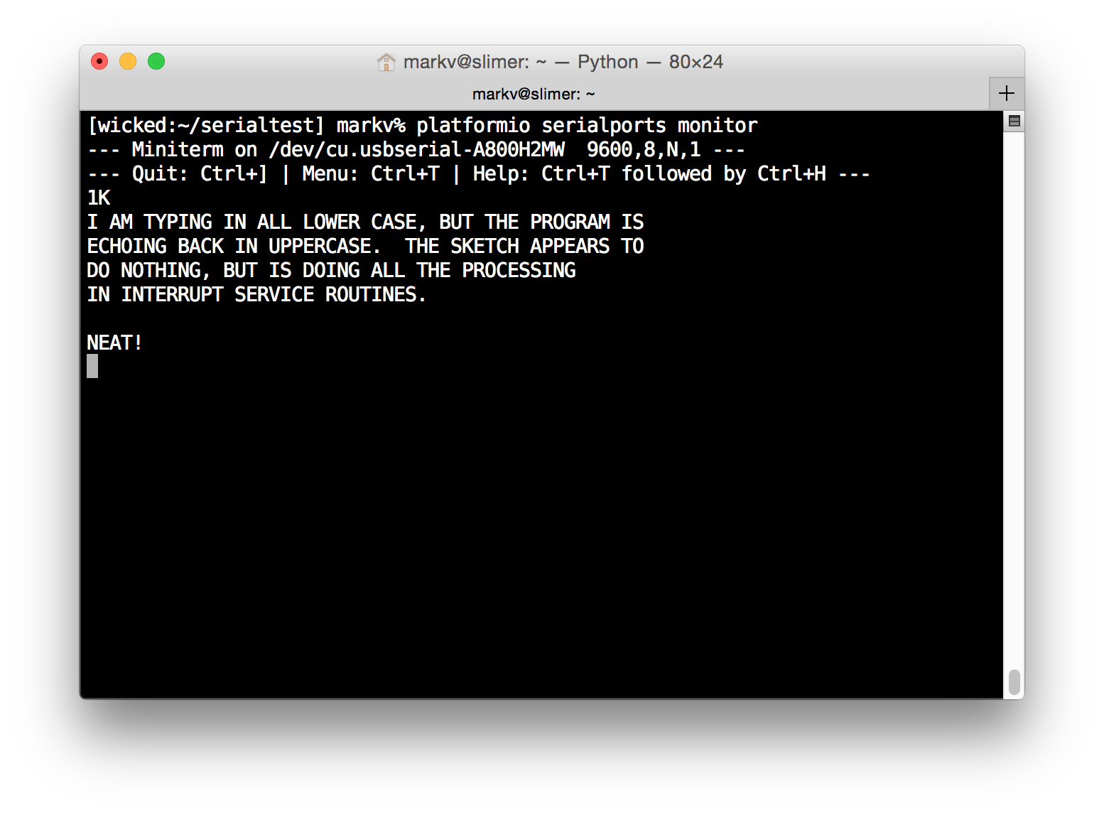
#include <stdint.h>
#include <avr/io.h>
#include <avr/interrupt.h>
#include <avr/pgmspace.h>
#include <util/delay.h>

////////////////////////////////////////////////////////////////////////

#define RX_BUFFER_SIZE	(128)
#define RX_BUFFER_MASK	(RX_BUFFER_SIZE-1)

uint8_t buffer_head = 0 ;
uint8_t buffer_tail = 0 ;
uint8_t buffer_count = 0 ;
uint8_t buffer[RX_BUFFER_SIZE] ;

ISR(USART_RX_vect)
{
    uint8_t c = UDR0 ;
    if (c >= 'a' && c <= 'z')
	c = 'A' + c - 'a' ;
    buffer[buffer_tail++] = c ;
    buffer_tail &= RX_BUFFER_MASK ;
    UCSR0B |= _BV(UDRIE0) ;
    buffer_count ++ ;
    if (buffer_count == RX_BUFFER_SIZE)
	UCSR0B &= ~_BV(RXCIE0) ;
}

ISR(USART_UDRE_vect)
{
    UDR0 = buffer[buffer_head++] ;
    buffer_head &= RX_BUFFER_MASK ;
    buffer_count -- ;
    if (buffer_count == 0)
	UCSR0B &= ~_BV(UDRIE0) ;
}

////////////////////////////////////////////////////////////////////////

#define BAUD	9600

#include <util/setbaud.h>

void
uart_init()
{
    UBRR0H = UBRRH_VALUE;
    UBRR0L = UBRRL_VALUE;

#if USE_2X
    UCSR0A |= _BV(U2X0);
#else
    UCSR0A &= ~(_BV(U2X0));
#endif
    UCSR0B = _BV(RXEN0) | _BV(TXEN0) | _BV(RXCIE0) ;
    UCSR0C = _BV(UCSZ01) | _BV(UCSZ00) ;
}

void
uart_putchar(char c)
{
    loop_until_bit_is_set(UCSR0A, UDRE0); /* Wait until data register empty. */
    UDR0 = c;
}

int
main()
{
    uart_init() ;
    uart_putchar('1') ;
    uart_putchar('K') ;
    uart_putchar('\n') ;

    sei() ;

    for (;;) ;
}
If you look at main, you'll see that it initializes the uart, prints out three characters (using the polled uart_putchar routine that we mentioned before) and the calls sei() which is the Set Interrupt Enable() routine. Then, the program enters a loop which appears to do nothing. In fact, all the operation of this program happens in the ISR routines, which aren't explicitly called at all. If you connect to the Arduino after burning this firmware (I use platformio's serial ports monitor, which is convenient) you can test it out.![]()
This program seems to have taught me what i need to know. I need to do a bit more thinking about exactly how I am going to use it in the final keyer project. I think that the main program will consist of my state switching code and generating all the dits and dashes. I'll augment the state machine to include a state which is entered when the buffer is empty, and whenever we are in the start state and a character is ready, we prefer to handle that rather than read from the paddles. When the character is complete, then we loop back to the start state.
Coming soon...
There is one bit of code left that I need to work out: how to generate the 700Hz audio sidetone. If we were using Arduino, that would be pretty simple, and just require the tone() call, but again, that would be a lot of code to include. Instead, we will initialize one of the on chip timer modules ourselves, and use it to generate the necessary 700Hz square wave on an output pin.
Once we have all that, the final program will be ready. We'll be pretty close in terms of size, and may require a bit of tweaking to get it under the 1K limit, but I am confident it's doable. I'll then do a couple of Youtube videos demonstrating its use, make sure the code is available from github and reasonably tidy, and provide hex files for download.
It's turning out to be a fun project. I hope you are enjoying it.
-
Space doesn't stretch forever in all directions...
12/08/2016 at 22:44 • 0 commentsOne of the goals of this project is to make the code capable of being entered into the Hackaday 1K code competition. This isn't perhaps as easy as it sounds: 1K is not a lot of memory, and the Arduino framework (as generally friendly as it is) isn't all that helpful if your goal is to use the smallest amount of memory that you can. As an example, consider the smallest Arduino sketch imaginable:
void
setup()
{
}

void
loop()
{
}
How much space does this simple sketch take up?AVR Memory Usage ---------------- Device: atmega328p Program: 444 bytes (1.4% Full) (.text + .data + .bootloader) Data: 9 bytes (0.4% Full) (.data + .bss + .noinit)Yep, 444 bytes out of our 1024 bytes, and we haven't even started to do anything yet.What happens if we include just a few additional library calls? Here is a simple program that simply blinks the LED on board once a second, and writes out the word BLINK each time.
void
setup()
{
    Serial.begin(9600) ;
    pinMode(13, OUTPUT) ;
}

void
loop()
{
    Serial.println("BLINK") ;
    digitalWrite(13, HIGH) ;
    delay(500) ;
    digitalWrite(13, LOW) ;
    delay(500) ;
}
How much memory does this use?AVR Memory Usage ---------------- Device: atmega328p Program: 1916 bytes (5.8% Full) (.text + .data + .bootloader) Data: 192 bytes (9.4% Full) (.data + .bss + .noinit)
Yep, 1916 bytes of flash! We are way over our 1K code, and we have barely done anything yet. Clearly if we are going to implement my 1Keyer in just 1K, we are going to have to be clever, and use some techniques which aren't part of the normal way of working with Arduino. As a hint to what's coming, I'll note that you don't have to use all the Arduino libraries to write code for Arduino microcontrollers. You can use avr-gcc directly (or via platformio) to compile the following simple C program which does nothing.
int
main()
{
    for (;;) ;
}
And how big is that?AVR Memory Usage ---------------- Device: atmega328p Program: 134 bytes (0.4% Full) (.text + .data + .bootloader) Data: 0 bytes (0.0% Full) (.data + .bss + .noinit)Just 134 bytes! Sure, we won't be able to use the convenient pinMode, digitalWrite and Serial commands if we do this, but we can recover space for all the functionality of those that we don't use.That will be the key to making this work. And, as it turns out, it's not particularly difficult to do simple things without this Arduino scaffolding.
Bonus: First of all, don't be terrified by this. We are going to dive a tiny bit into the actual machine code that is generated by the C compiler to see how we can eke out some more space. If this doesn't make any sense to you, it's entirely natural, and don't get frustrated or depressed. Try reading a machine language tutorial like this one and even if it doesn't make sense, try to follow along, and if you have any questions, feel free to leave comments.
We can figure out what all these 134 bytes are doing if we use the avr-objdump program which is part of avr-gcc. Again, just teasing, here's what happens when I tell avr-objdump to disassemble the firmware that we generated from that empty main() program above:
> ~/.platformio/packages/toolchain-atmelavr/bin/avr-objdump -z -d -C .pioenvs/uno/firmware.elf

.pioenvs/uno/firmware.elf:     file format elf32-avr


Disassembly of section .text:

00000000 <__vectors>:
   0:	0c 94 34 00 	jmp	0x68	; 0x68 <__ctors_end>
   4:	0c 94 3e 00 	jmp	0x7c	; 0x7c <__bad_interrupt>
   8:	0c 94 3e 00 	jmp	0x7c	; 0x7c <__bad_interrupt>
   c:	0c 94 3e 00 	jmp	0x7c	; 0x7c <__bad_interrupt>
  10:	0c 94 3e 00 	jmp	0x7c	; 0x7c <__bad_interrupt>
  14:	0c 94 3e 00 	jmp	0x7c	; 0x7c <__bad_interrupt>
  18:	0c 94 3e 00 	jmp	0x7c	; 0x7c <__bad_interrupt>
  1c:	0c 94 3e 00 	jmp	0x7c	; 0x7c <__bad_interrupt>
  20:	0c 94 3e 00 	jmp	0x7c	; 0x7c <__bad_interrupt>
  24:	0c 94 3e 00 	jmp	0x7c	; 0x7c <__bad_interrupt>
  28:	0c 94 3e 00 	jmp	0x7c	; 0x7c <__bad_interrupt>
  2c:	0c 94 3e 00 	jmp	0x7c	; 0x7c <__bad_interrupt>
  30:	0c 94 3e 00 	jmp	0x7c	; 0x7c <__bad_interrupt>
  34:	0c 94 3e 00 	jmp	0x7c	; 0x7c <__bad_interrupt>
  38:	0c 94 3e 00 	jmp	0x7c	; 0x7c <__bad_interrupt>
  3c:	0c 94 3e 00 	jmp	0x7c	; 0x7c <__bad_interrupt>
  40:	0c 94 3e 00 	jmp	0x7c	; 0x7c <__bad_interrupt>
  44:	0c 94 3e 00 	jmp	0x7c	; 0x7c <__bad_interrupt>
  48:	0c 94 3e 00 	jmp	0x7c	; 0x7c <__bad_interrupt>
  4c:	0c 94 3e 00 	jmp	0x7c	; 0x7c <__bad_interrupt>
  50:	0c 94 3e 00 	jmp	0x7c	; 0x7c <__bad_interrupt>
  54:	0c 94 3e 00 	jmp	0x7c	; 0x7c <__bad_interrupt>
  58:	0c 94 3e 00 	jmp	0x7c	; 0x7c <__bad_interrupt>
  5c:	0c 94 3e 00 	jmp	0x7c	; 0x7c <__bad_interrupt>
  60:	0c 94 3e 00 	jmp	0x7c	; 0x7c <__bad_interrupt>
  64:	0c 94 3e 00 	jmp	0x7c	; 0x7c <__bad_interrupt>

00000068 <__ctors_end>:
  68:	11 24       	eor	r1, r1
  6a:	1f be       	out	0x3f, r1	; 63
  6c:	cf ef       	ldi	r28, 0xFF	; 255
  6e:	d8 e0       	ldi	r29, 0x08	; 8
  70:	de bf       	out	0x3e, r29	; 62
  72:	cd bf       	out	0x3d, r28	; 61
  74:	0e 94 40 00 	call	0x80	; 0x80
  78:	0c 94 41 00 	jmp	0x82	; 0x82 <_exit>

0000007c <__bad_interrupt>:
  7c:	0c 94 00 00 	jmp	0	; 0x0 <__vectors>

00000080 :
  80:	ff cf       	rjmp	.-2      	; 0x80

00000082 <_exit>:
  82:	f8 94       	cli

00000084 <__stop_program>:
  84:	ff cf       	rjmp	.-2      	; 0x84 <__stop_program>
This is the raw assembly and machine code for the program we just produced. To really understand what is going on here, you'll have to probably read the datasheets for the Atmel ATmega328, which is the chip this is compiled for, but briefly here are the major parts:
- It all starts at address 0 with the interrupt vector table. When the program receives an interrupt (which I'll perhaps cover a bit more in the future) then it uses the interrupt number to jump to the appropriate handler. The ATmega328 has 26 separate possible interrupts, each one of which has a jmp instruction to tell it to go when it receives that type of interrupt. When the program starts, it will start at address 0, which contains a jmp to the location __ctors_end.
- __ctors_end() is responsible for doing all the necessary setup. In this case, it doesn't do much. It clears the contents of register1 (eor r1, r1 uses exclusive or to make sure r1 contains zero). It then stores it in the SREG, which is the status register.
- The four instructions at 0x6c setup the stack pointer to point to the end of RAM. For the ATmega328p, the end of ram is at address 0x8FF, and the out instructions write that into the SPH and SPL special registers.
- It then issues a call() to address 0x80. If you look at that instruction, that just does a relative jump to the address 2 bytes before the current PC location. When this executes, the PC has already incremented, so this basically resets the PC to execute the same instruction over and over. In other words, it implements the infinite loop that I coded in the main().
One thing that you can see from this is that most of the storage used by this program (104 out of the 134 bytes) is actually the interrupt table. If we don't want to use the interrupt service table (we never enabled most or all of the interrupts available) we could potentially recover all that space. We might have to resort to such extreme measures in the future. It depends on how far we get before we run out of space. But there are all sorts of games we can play.
For more hints about the sort of thing we will be doing, you can look at this article by Nerd Ralph.
-
State (Machine) of the Union...
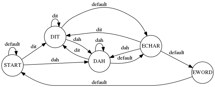
12/08/2016 at 19:52 • 0 commentsI thought I'd write down these notes quickly do demonstrate how the keyer works in an abstract sense, minus any details of implementation. I'm going to ignore the serial interface aspect of it for now, and concentrate just on how the part that reads the state of the iambic paddles and schedules the dits and dahs will work.
It will be implemented as a Finite State Machine. The idea is very simple. The machine has an internal state (which you can think of as just being an identifier) and depending on particular conditions or events. When it is in a particular state, it might do some action, then attempt to read an event or condition. Depending on what state you are in, and what condition you read, you may either remain in the current state (and do the action again and then read actions again...) or you might hop to a different state.
If we represent states as circles and conditions as labelled arcs, you can map out how the keyer will work like this:
![]()
This might be a little bit confusing, so I'll explain. States are represented by circles, with names in all capital letters. Conditions are labels on arcs, and if the condition is satisfied, then the machine moves into the next state. For instance, we begin in the START state. Basically, this state is just waiting for something to happen. If we see a dit condition satisfied (somebody closed the dit switch) then we move into the state DIT. Similarly, if the dah condition is satisfied, then we move to the DAH state. If neither of those conditions is satisfied, we simply remain in the START state by taking the default arc.
So, what happens when we are in the DIT state? First, we send a dit! That basically works by setting a particular pin high for a given amount of time and then setting it low for a given time. You might implement this in Arduino-ish code like this:
void
do_dit()
{
    digitalWrite(output_pin, HIGH) ;
    delay(ditlen) ;
    digitalWrite(output_pin, LOW) ;
    delay(ditlen) ;
}
We will ignore how we compute ditlen for now, let's just say we know how to compute ditlen for a given desired speed. While we are at it, we could go ahead and show you how we do dahs:void do_dah() // insert joke about Camptown ladies here... { digitalWrite(output_pin, HIGH) ; delay(3*ditlen) ; digitalWrite(output_pin, LOW) ; delay(ditlen) ; }Same code, except that we hold the key down (write a high value to the output pin) for three times as long.So, when we are in state DIT, we call do_dit(), and then scan to see what conditions are satisfied. Perhaps we are continuing to hold down the dit switch closed. In that case, we can just stay in our current state. On the next iteration, we'll resend a dit by calling do_dit(), and keep doing that until we stop holding that key down. If however we hold dah switch close, we can skip over to sending by entering the DAH state. If after sending a dit we don't see either key on, then we are done with the character, and will go to the ECHAR state.
There is one subtlety. We want the situation to be such that if we hold both switches closed, we alternate with dits and dahs. We can do this by checking this condition first: if you re in the DIT state, first check to see if the dah switch is closed. If it is, then go to DAH. It doesn't matter if dit continues to be closed. Similarly, if you are in the DAH state, first check to see if the dit switch is closed, and switch to DIT if is.
Let's walk through how the character C might be sent. C is dah dit dah dit.
- We begin in state START.
- The user closes the dah switch, which causes us to enter the DAH state. We start sending the dah.
- While the dah is being sent, the user closes the dit switch.
- When the dah completes, the DAH state queries the action. It checks the dit switch first, and so moves to the DIT state.
- DIT sends the dit, and then reads the keys again.
- The user continues to hold both keys down, so the the DIT state reads that the dah switch is pressed, and we move to state DAH.
- The DAH state sends the dah, again reads the keys, the dit key is still pressed, so it moves to the dah state.
- The user lets go of both switches. When the final DIT is done sending, the DIT state sees that neither switch is set, and so follows the default path to the ECHAR state (end of character).
- The ECHAR delays for two dit times (the space between two characters is three dits long, but you already sent one as part of your call to do_dit() or do_dah()), and then reads switches. Again, if dit or dah is depressed, we go back to those states to start a new character. If they are not depressed, then we go to EWORD, where four additional dit times are spent to generate the necessary 7 dits between words, and then we return to the start.
And that's pretty much it! The rest is just implementation details, which will be part of my first real code posting coming soon. Stay tuned!
-
Proposed Features for the 1Keyer
12/08/2016 at 05:09 • 0 comments- designed to make use of inexpensive Arduino Micro/Nano modules for ease of construction and low cost.
- small but flexible software, written to provide a flexible framework for future experimentation.
- implements an iambic keyboard controller. Implement both "mode A" and "mode B", with user controlled adjustable speed via a potentiometer.
- serial interface which implements two different use cases:
- data read from the serial data port is automatically sent via morse code
- characters keyed with the paddle are also translated into ASCII and sent out the serial port
- keying output to control key a radio transmitter
- a sidetone output, which is a 700Hz audio to provide audio feedback that the keyer is working
- Fits in just 1K of Flash, to make it an entry in the Hackaday 1K Code Contest!
-
Motivation
12/07/2016 at 22:47 • 0 commentsOn my blog, I've written a number of posts about sending Morse code using the Arduino. They mostly have centered around using an Arduino as a beacon controller to automate the repeated sending of simple messages via Morse code. Despite being licensed as K6HX and having an Amateur Extra class license, I'm actually pretty bad at both sending and receiving Morse code. But, from time to time, I give it a whirl, and if you keep to embarrassingly slow data rates, I can barely decode callsigns and some tiny amounts of traffic. I need more practice.
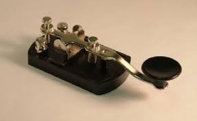
But I'm even more of a novice at sending Morse code. If you've seen anyone send Morse code, you probably imagine them tapping out the signals on a gadget like this, which is normally called a "straight key":
There are reasons to like such a gadget. They are simple, and straightforward. They are really just a switch. You can homebrew crude versions, or spend lots of money on carefully balanced and machined beauties. But these straight keys all require some degree of skill. Ideally, the dots and dashes (more commonly called dits and dahs in amateur radio) are supposed to have dashes be three times as long as a dot, and the time between these individual elements should be as long as a dot. Getting the timing just right can be difficult, and often Morse code operators can be distinguished by the way they deviate from this timing. You'll often hear that such people have a distinctive "fist."![]()
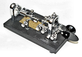
But there are other ways to send Morse code as well. Various mechanical means of sending dits and dahs that are more evenly spaced, usually by a semiautomatic key such as those made by Vibroplex which are often referred to as "bugs." They look like this:
![]() At the right you can see a paddle which is had between the thumb and forefinger of the right hand. When pressed to the right, it operates as a norrmal key, and is used to generate dashes. But when pushed to the left, a mechanical pendulum frequently makes and breaks contact, which allows the user to send a nearly continuous stream of dits. The mechanism itself is pretty complicated and fussy, to these keys are pretty expensive, and can require considerable skill to use.
At the right you can see a paddle which is had between the thumb and forefinger of the right hand. When pressed to the right, it operates as a norrmal key, and is used to generate dashes. But when pushed to the left, a mechanical pendulum frequently makes and breaks contact, which allows the user to send a nearly continuous stream of dits. The mechanism itself is pretty complicated and fussy, to these keys are pretty expensive, and can require considerable skill to use.The type of key that I'm most interested in are iambic keys (or paddles) which have two different keys for dots and dashes. If you push the left switch to the right, you are closing the "dit" circuit, and if you push the right switch to the left, you are closing the "dah" circuit. These are often used in combination with a special keyer circuit, which generates all the timing, and often implements an interesting feature: if you squeeze both switches, you end up with an alternating string of dits and dahs. Thus, you can send a character like C by starting the character by squeezing the right key to the left (which starts a dah), then moving the left key to the right, which will start alternating dit-dah-dit and then letting go of both to finish the character.
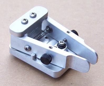
I have this tiny little iambic paddle that I haven't used nearly enough to become proficient.
http://www.americanmorse.com/dcp.htm
![]()
So, my goal is to implement a simple keyer that you can easily use in your shack or other homebrew radio projects. I like the idea of using the ATtiny13, which has 8 pins and would seamingly be ideal for this purpose:
- VCC
- side tone switch
- sidetone audio
- push button switch
- keying output
- dit paddle
- dah paddle
- ground
Which is roughly the same as K1EL's excellent keyer chip that you can order from him for just $8. His stuff is awesome, and if you are an really wanting a keyer with a lot of features, you'd be smart to just order one of his chips or even his more sophisticated kits. But I wanted one feature not implemented on this simple chip: I wanted to be able to send serial data to it, and have it automatically translate it into the right keying sequence. That requires two more pins (for Rx and Tx) which meant that I had to go to a larger version of the chip. But economically, it hardly makes sense to use the ATtiny2313 or a larger chip. If you order parts from China, you can get an Arduino Mini for about $3 (or maybe even less) and it will have the power regulators, crystals and a reset switch on board. I've got a pile of ones that run on 3.3V at 8Mhz, and that will be the target development platform for this code.
My next update will include a list of features that I plan to implement. I am going to keep all the code to 1K or less both to keep it simple, and to make it eligible for the Hackaday 1K code competition. But keeping the code short has an additional benefit: it should be relatively easy to modify for your own devices, and/or include it in other radio related projects. I'll be releasing the full code under a BSD license, so feel free to hack it and use it as you like.
 At the right you can see a paddle which is had between the thumb and forefinger of the right hand. When pressed to the right, it operates as a norrmal key, and is used to generate dashes. But when pushed to the left, a mechanical pendulum frequently makes and breaks contact, which allows the user to send a nearly continuous stream of dits. The mechanism itself is pretty complicated and fussy, to these keys are pretty expensive, and can require considerable skill to use.