Close
0%
0%

Wigglegram esp32-cam

Making wigglegrams using some esp32-cam boards

Similar projects worth following

I was inspired by wigglegrams a while ago and decided to start taking these photos as well. Initially I was going to build a lens much like the source of inspiration. One day I was looking in my hardware box and realized I could emulate the lens technique with the handful of esp32-cam modules I had laying around. 

1.gif

Initial test image

Graphics Interchange Format - 1.68 MB - 11/30/2022 at 15:56

Preview

  • 4 × ESP32-CAM
  • 4 × Microsd Card 32GB Or whatever you can get your hands on
  • 1 × RC UBEC 5V ~150mA * number of ESP32-CAM modules. I had a 3A one laying around so I used it
  • 1 × 3mm Baltic Birch Plywood

  • New prototype

    Bryant11/30/2022 at 21:57 0 comments

    Rework

    The first thing I realized from the first success was that my method of "cut some slots in a cardboard box, shove the boards in them, and hold a bunch of wires to try to get a photo" was not only not sustainable but produced terrible results. Along with the power issues it was quickly realized that my cardboard setup was insufficient as the boards were just too floppy to keep them aligned. Additionally the camera modules were loose and in no way stable.

    Addressing floppy cameras

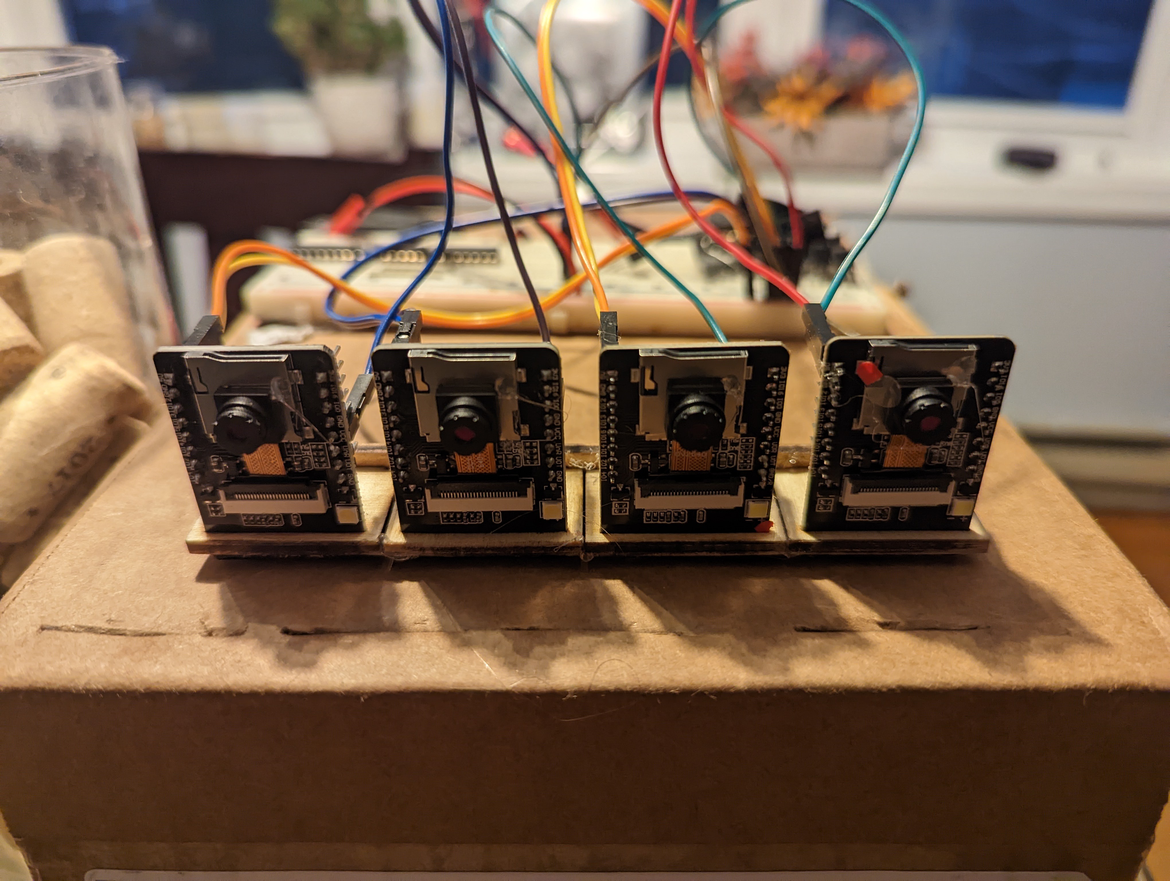
    A quick fix to address the cameras supported only by their cables was to put a drop of hot flue on the corner of each and attach it to the sd card shield. This is easy to implement and is also reversible if I come up with a better mechanism in the future. This system means that the camera will always be aligned with respect to the board and not necessarily with each other. 

    Addressing misaligned boards

    A slightly less quick fix for the board alignment was to create a system of board carriers and one board carrier back plane. Boards would then be aligned with respect to the carriers and each carrier to the back plane. A few minutes of laser cutting and I had an ok-ish system of holding the boards. The boards were pushed into the carriers, visually aligned vertically, and tacked in place with some hot glue. Then each of the carriers was glued on to the back plane making sure that the alignment of each carrier was close. This system is ok for a prototype but I will need to revise it in the future to have better tolerances and be more foolproof for assembly.

    Addressing funky wiring 

    The last bit I saw I needed to fix to make the prototype work better was to make the wiring more secure. My old proto board was not holding the proto wires well and everything was just too wonky to get any sort of result without doing hand gymnastics. I grabbed a perf board and some female pin headers and soldered them up to make three distinct channels for power and communication

    Second success

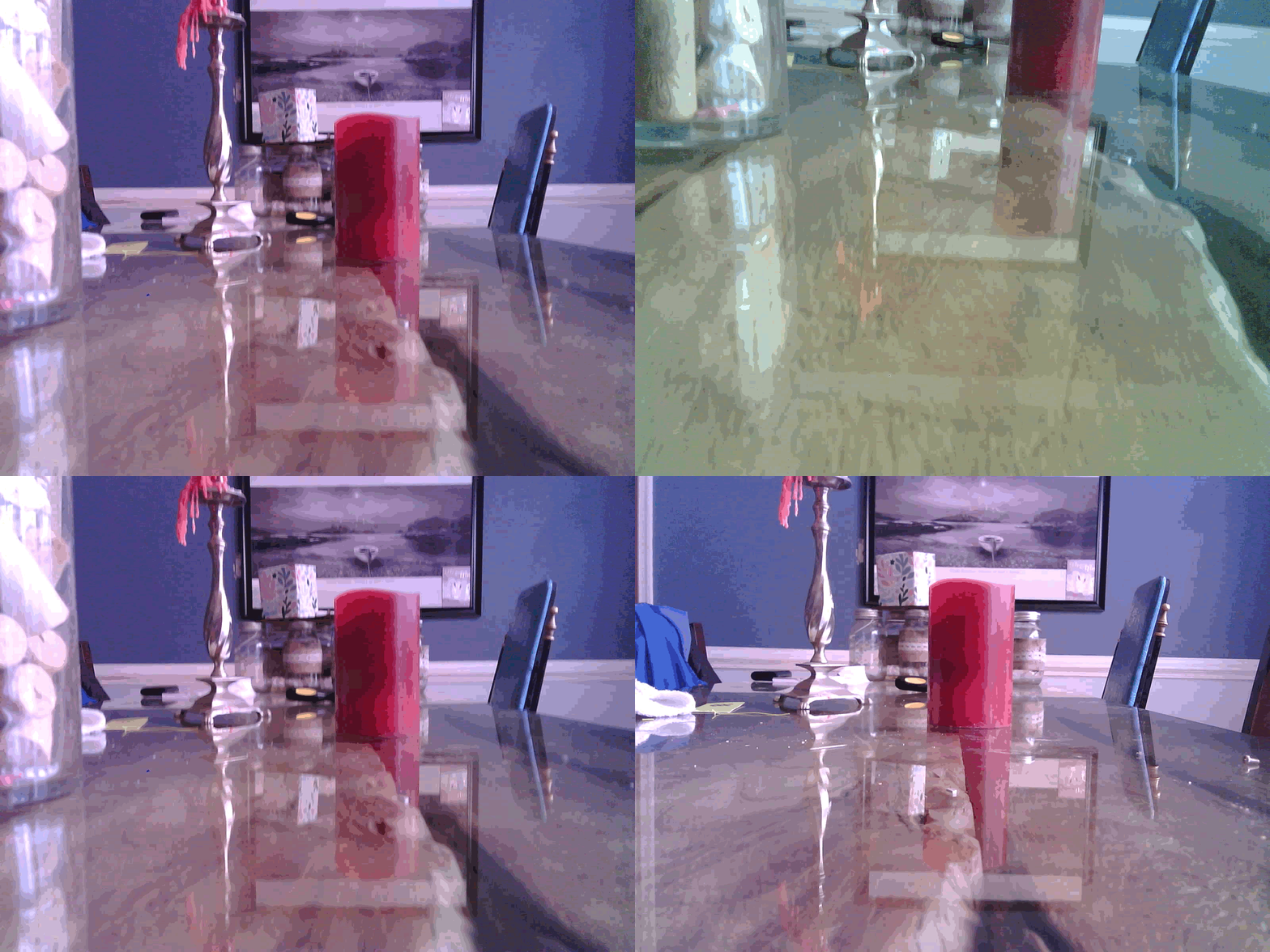
    All of the above fixes combined allowed me to take an image that was slightly better but still lacking from the result I expected. A few things to note:

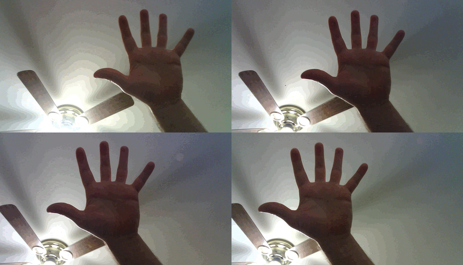
    • The camera needs to be in decent lighting. A dimly lit room will result in dark and or green images.
    • The camera needs a little bit of time to white balance. Otherwise the images will come out with off colors
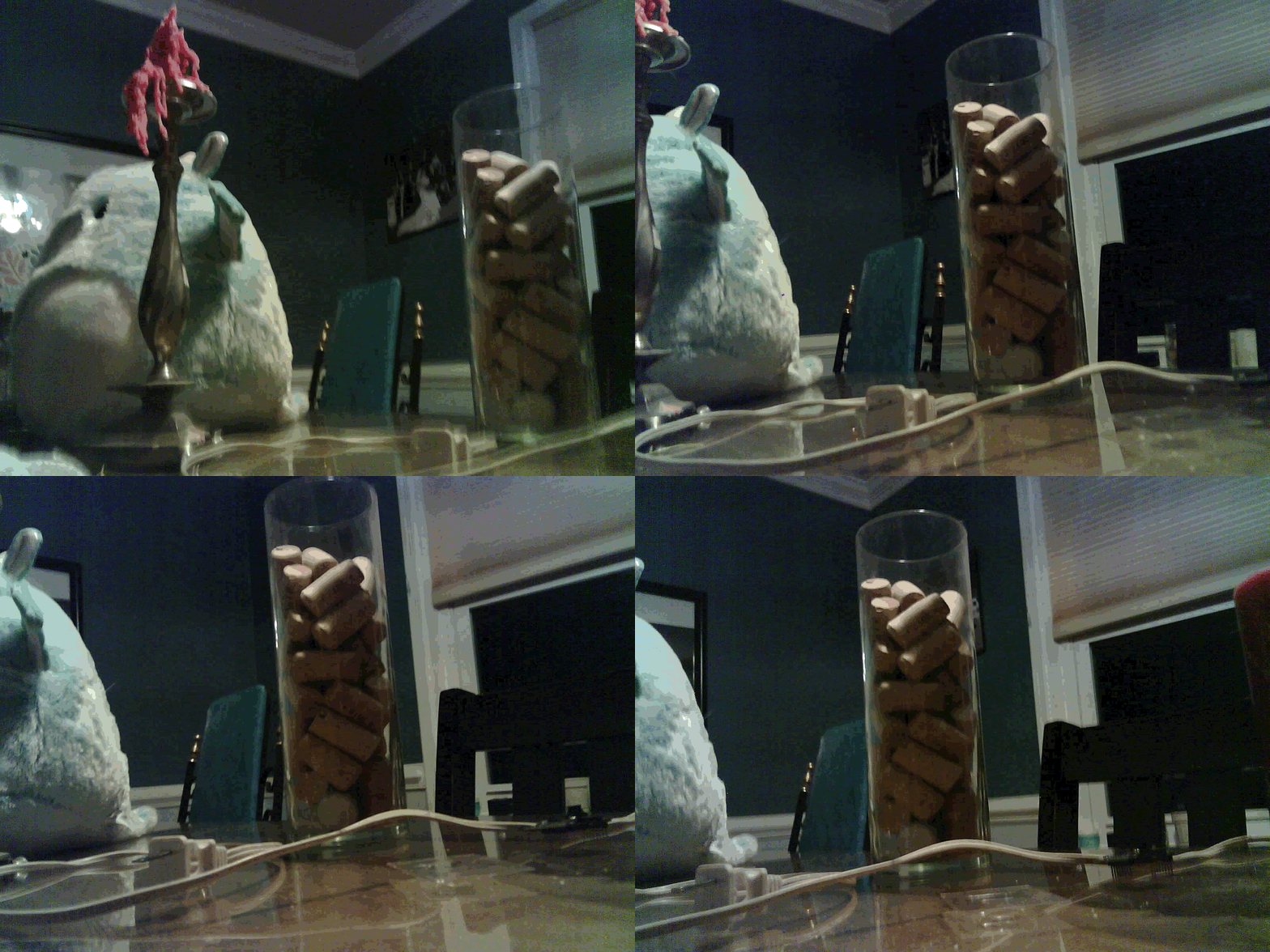
    • The resulting images still need to be aligned. As all the cameras are facing the same direction the resulting image is "virtually focused" on infinity. Creating a GIF without any additional effort will result in a panning effect rather than the 3d effect I was hoping for
    • Manually aligning the images is possible and will produce the 3d effect but the results will need to be cropped
    • Vertical alignment is still not perfect. Maybe its because there are multiple different camera modules or maybe the carriers are not perfect. I have a few ideas to address this in the future as well

    Unaligned

    Aligned

  • Starting Ideas and Early Failures

    Bryant11/30/2022 at 21:52 0 comments

    I saw wigglegrams a long time ago. I had planned on building a lens for my dslr but pivoted when I remembered I have a handful of ESP32-CAM modules. 

    The initial plan of action was:

    1. Have one esp32-cam module be the controller
    2. Have one-n additional esp32-cam modules be triggered by the controller
    3. Each module would, when triggered, take an image and save it to the sd card
    4. Images would then be brought onto a computer for editing and later scripted to produce the results

    The first challenge I faced when developing the prototype was having one controller (the 'dom') signal the other controllers (the 'subs') to all take pictures simultaneously. 

    First Failure

    My first attempt was to use the Wire. After writing up some code and preparing two modules I set out to test it. I hastily wired everything up with prototype wires and powered it on. The dom proceeded to take two images and then the camera became non-responsive. Looking at the camera config I saw that the framebuffer was set to two. Setting it to 5 allowed me to take 5 images before failing. I thought that this must be a bug in the library as the sample code had the module going to sleep after taking an image. 

    I set out to produce a minimal example before going to submit a bug when it just started working. Clearly I had something in my code that was interfering with the camera. After going from function to function I finally discovered that the onewire interface was on a pin used by the camera module itself. Fail on me for not reading.

    Second, Third, Fourth? Failure

    After my frustrations with not reading I set out to re-implement the communications with a different pin. Problem was that the Wire library doesn't support bitbang mode. I found a library that would solve all my problems but then ran into camera failures again. Doh, a bunch of other pins are also used. 

    Eventually I actually read (and comprehended!) the docs and used a couple of pins that were not tied to the camera. Got the dom taking images, got communications to a single sub working and taking images, now just need to save them. Fail. The other pins I chose were tied to the SD card. After a moment away from the project I figured out that I had been adding extra complexity the whole time. There is already an open channel to communicate and I had been using it the whole time ... for debugging.

    First success

    I once again rewrote the communications to use the onboard serial ports. Since it is unidirectional the dom's TX pin is connected to all of the sub's RX pins. The sub will read from the Serial until it gets a \r or \n character. At that point the message is "processed". If the message doesn't start with a þ then it is ignored. This will allow me to keep debugging while only attached to a sub module.

    The code evolved and a few new features were added and finally I was ready to test "something". Using a proto board I connected all the power pins and all of the communication pins. I added in a UBEC from my RC parts box to provide power from a lipo and things started to come to life ... just not everything. 

    I quickly found out that my old tired proto board was not up for the job of keeping the pins in constant contact and any sort of movement would cause one or more of the modules to loose power or loose connection. Wanting to just get a proof of concept I played twister with my fingers holding pins at various angles to get everything to fire once and finally ... success but a disappointing one. 

    In the next post I will go over the issues with this setup and how I resolved them.

View all 2 project logs

Enjoy this project?

Share

Discussions

Similar Projects

Does this project spark your interest?

Become a member to follow this project and never miss any updates