-
1Proceso de impresión - Printing process
En la publicación se encuentran los archivos .STL de todas las piezas a imprimir; se detallan los aspectos relevantes de configuración de cada una:
- Pata fija: 20% infill
- Pata móvil: 20% infill
- Placas para bisagra: 40% infill
- Piezas auxiliares: 10% infill
- Masa: 10% infill
In the documentation you can find every .STL file nedeed for the printing process. Relevant aspects of the process are listed below:
- Stationary Jaw: 20'% infill
- Moving Jaw: 20% infill
- Hinge sheets: 40% infill
- Auxiliary pieces: 10% infill
- Mass: 10% infill
-
2Ensamble - Assembly
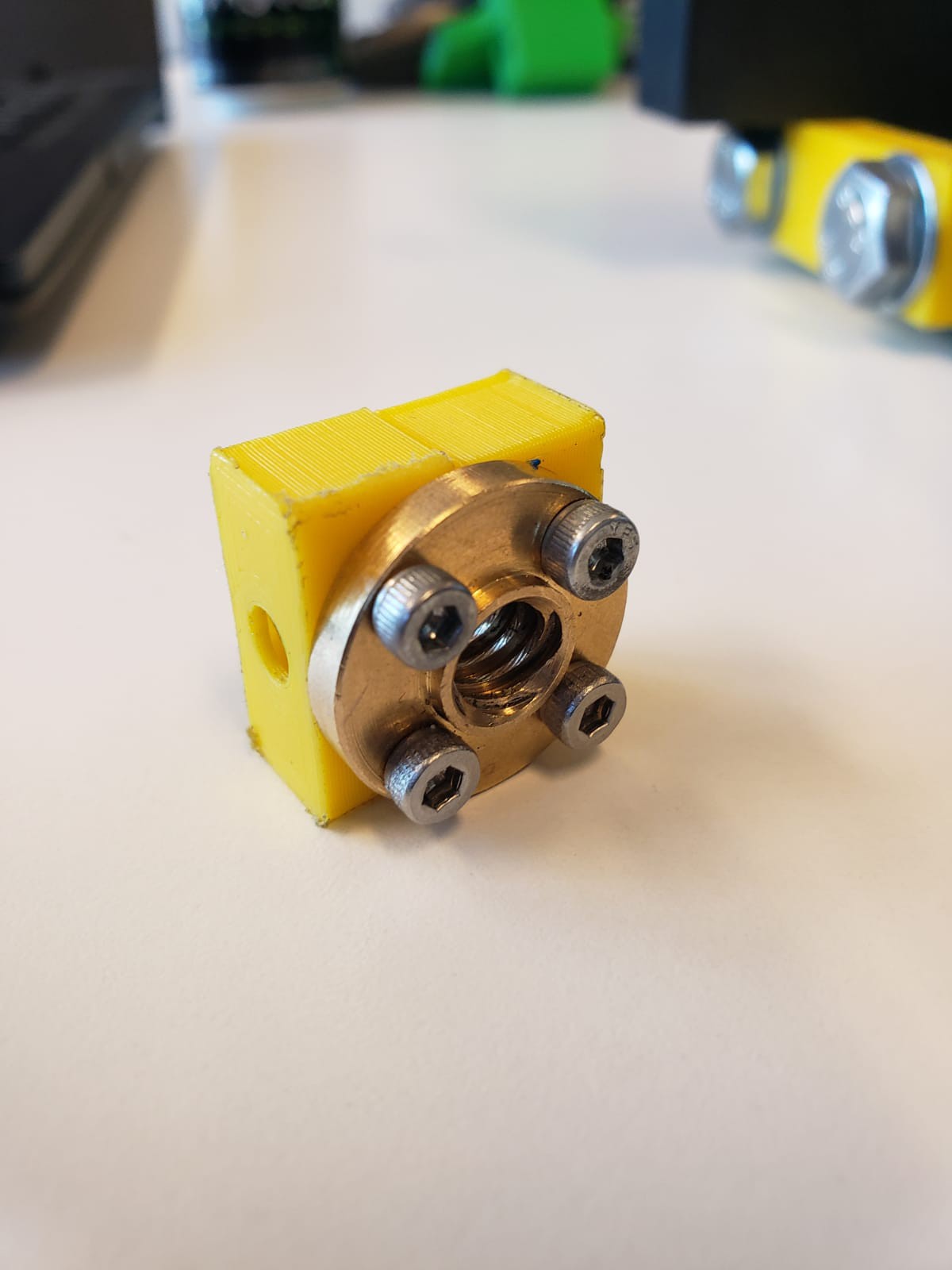
Primero se atornillan las piezas auxiliares a la tuerca T8 mediante 4 pernos M3.
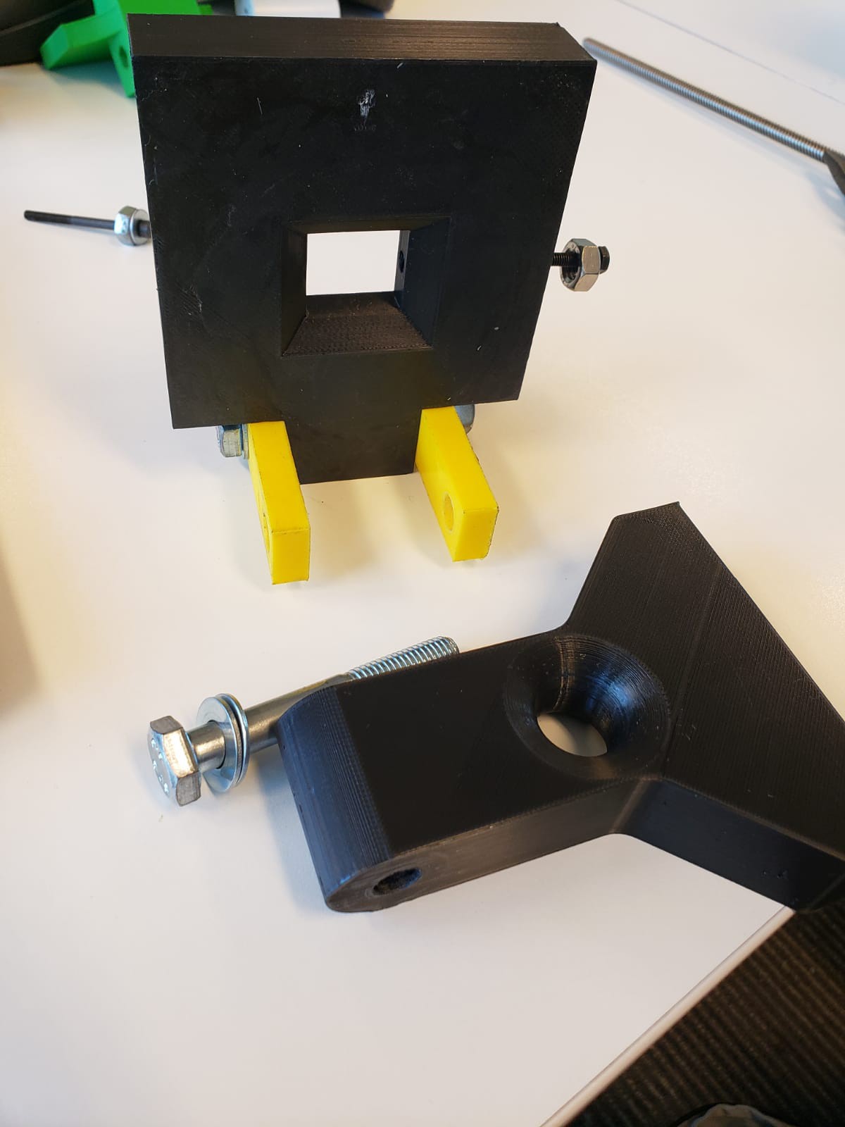
Se hace pasar uno de los tornillos de 10mm por una de las placas laterales y posteriormente por una de las patas, se atornillan y se repite el proceso con la otra pata.
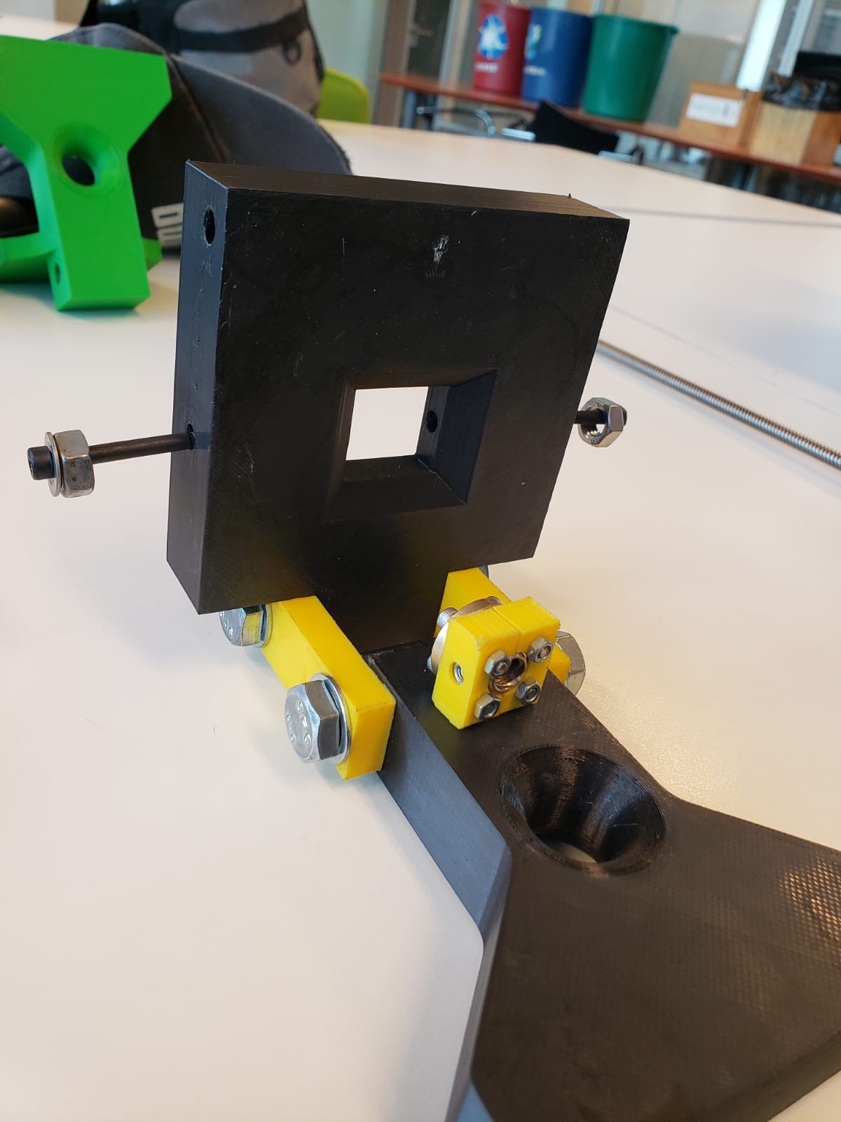
Luego mediante el uso de pernos M5 se atornilla el conjunto pieza auxiliar-tuerca al centro de la pata fija.
![]()
![]()
![]()
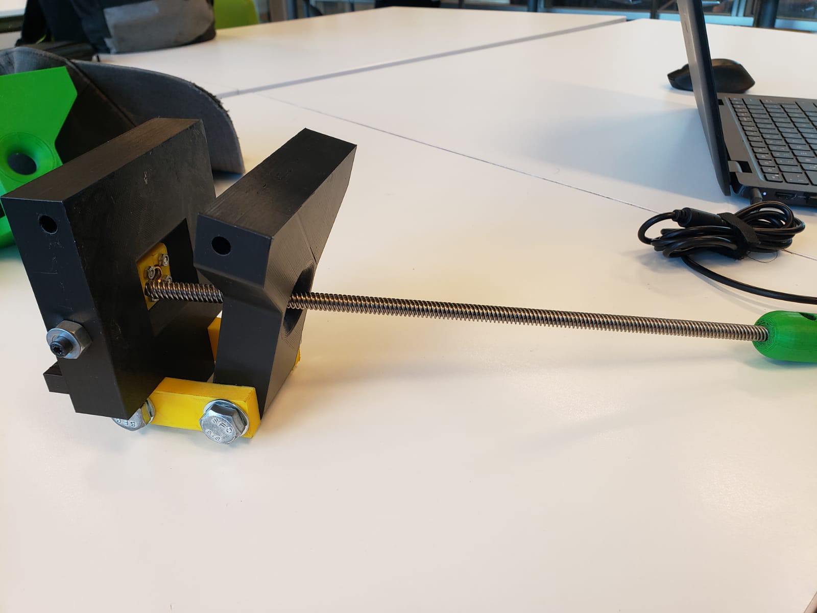
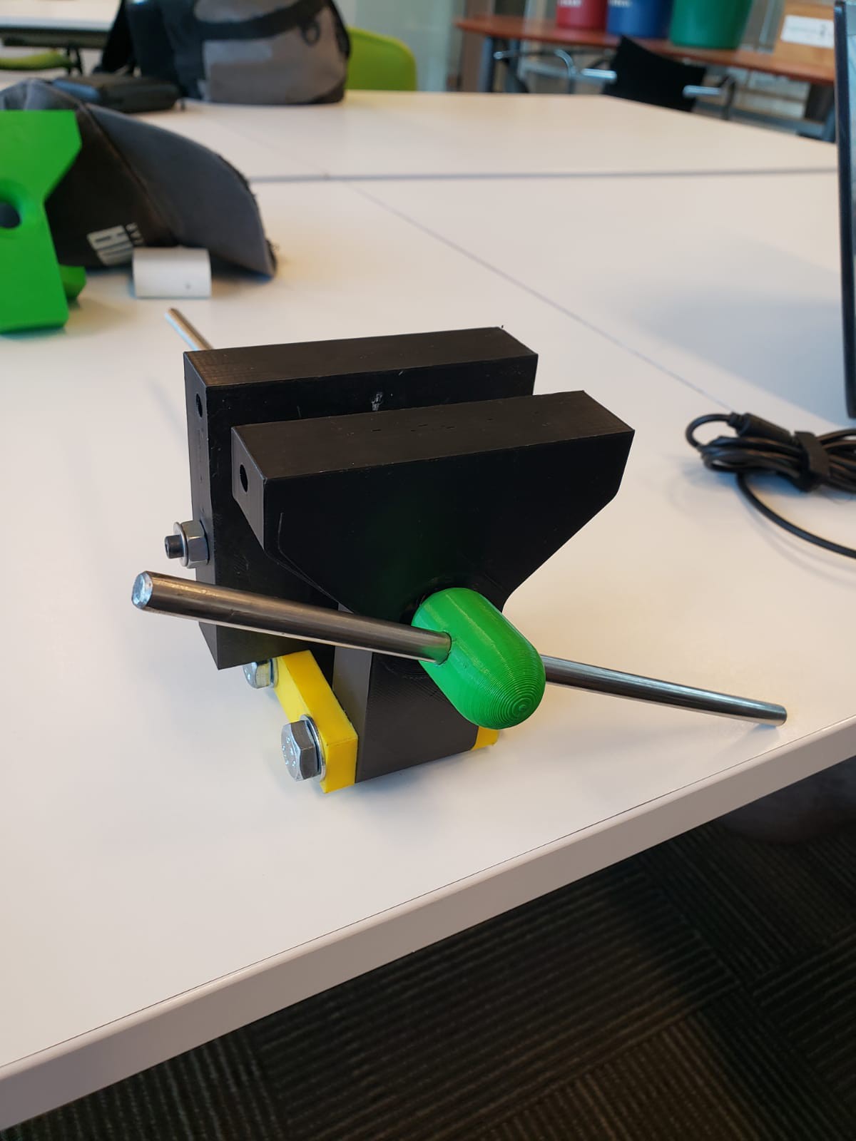
Luego de eso se hace pasar el tornillo de 8mm a través del agujero de ambas patas y se atornilla a la tuerca. Posteriormente se pega la masa al tornillo con el uso de pegamento epóxico.
![]()
Finalmente se hace pasar el fierro para el mango.
![]()
First of all, the auxiliary pieces are bolted on the T8 nut using 4 M3 nuts. One of the 10mm nuts is placed through the hinge piece and one of the jaws, it is bolted on, and the process is repeated with the other jaw.
After that, using M5 nuts, the aforementioned nut-auxiliary piece set is bolted on the stationary jaw.
Then, the 8mm bolt is placed though the perforations of both jaws and is bolted on the nut. Afterwards, the mass is glued to the bolt using epoxy glue.
Finally, the steel bar is placed through the mass in order to work as a handle.
Tornillo de escritorio - Bench Vise
Tornillo de escritorio; emulando parcialmente el diseño de tornillos de herrero.
Discussions
Become a Hackaday.io Member
Create an account to leave a comment. Already have an account? Log In.