SHAOS
SHAOS-
Final fix
01/08/2017 at 02:51 • 0 commentsI corrected last line to compensate 3-cycle overhead for every frame and also fixed order of patterns at the bottom of the screen - perfect version to burn my 1st OTP MCU :)
Final version is 445 words long (87% of PIC12C508) and available on GitLab
![]()
Source code also has schematics in it as a comment:
;       +5V
;      .--*
;      #  |  PIC12C508
; 470* #  |   ---v---
;      #  \--|1     8|- GND
;      | NC -|2     7|--###-\  1.5 kOhm
; SYNC *-----|3     6|--###--* 680 Ohm
;      | IN -|4     5|--###-/| 330 Ohm
;      |      -------        |
;       ----------------###--*---> VIDEO (8 gray levels)
;                     1 kOhm
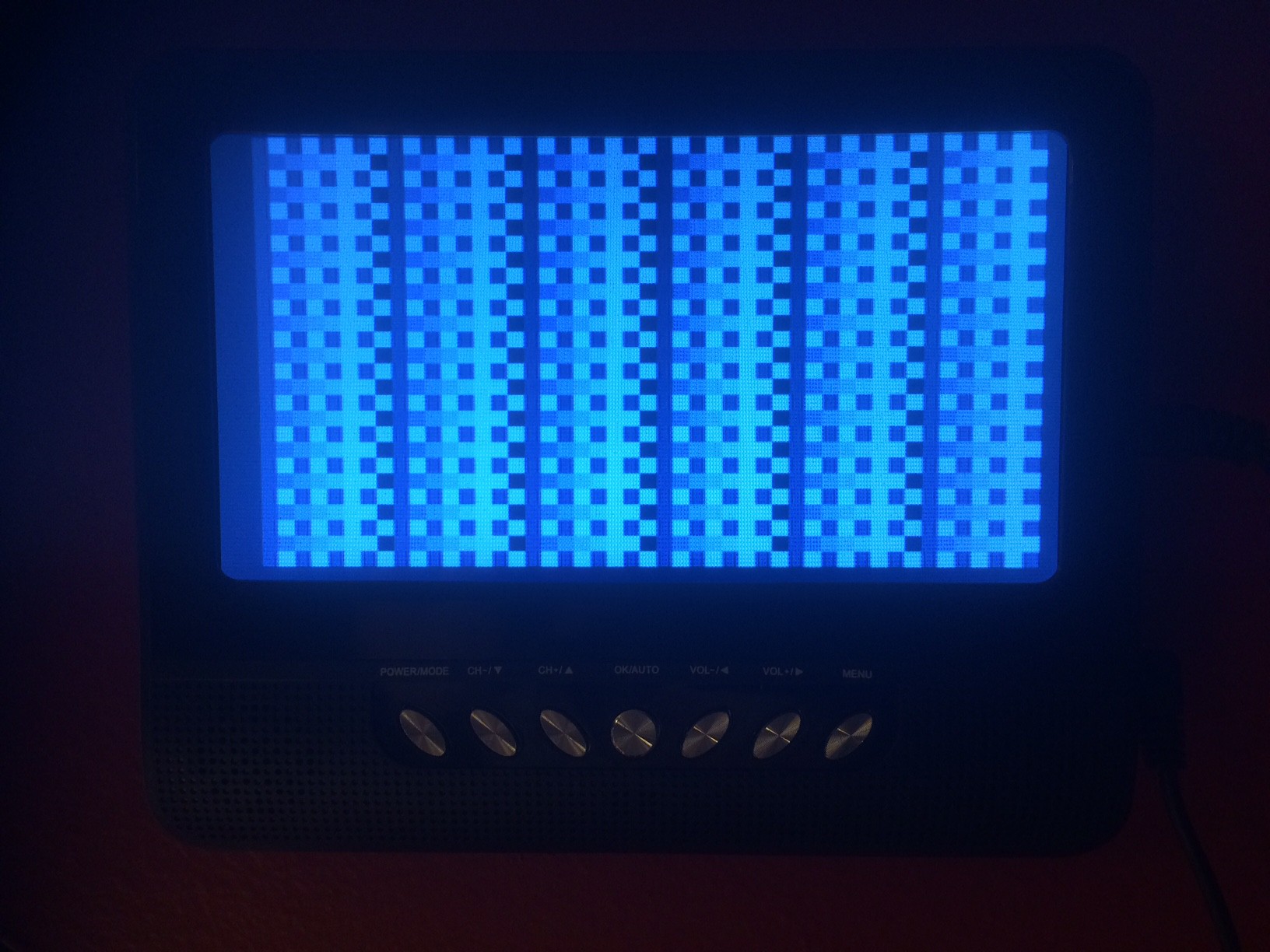
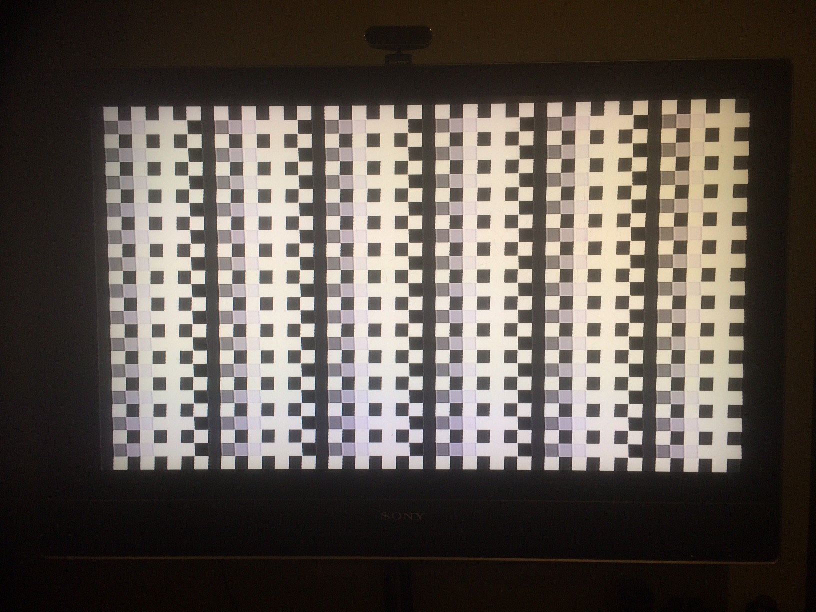
UPDATE: Another 2 TVs running by OTP PC12C508A, both SONY - big CRT one (4:3):
![]()
and big LCD one (16:9):
![]()
with video :)
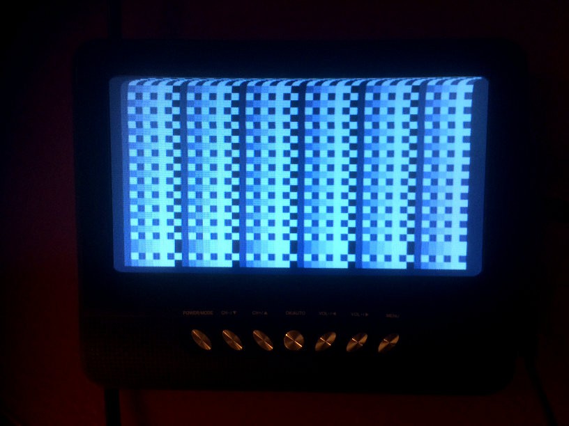
As you can see last few shades (5,6,7) are too bright and looks all white (may be because of 1.5V max amplitude). Also there is a space for 48th column on the left side - I'll add it in the next version that will be re-written for heavy macros usage to represent repeating code for visibility purposes...
-
Fixed
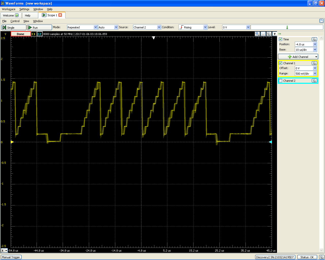
01/06/2017 at 05:45 • 7 commentsIt's already a little bit too late, but this is a fix to make frame sync work :)
--- a/PIC12-T1.ASM
+++ b/PIC12-T1.ASM
@@ -23,7 +23,7 @@ Line_:
  movwf TempN ; 1/7
 Line_loop: ; 15*3-1=44/51
  decfsz TempN,f ; (1/1)
- goto Line0loop ; (2/3)
+ goto Line_loop ; (2/3)
  nop ; 1/52

  clrf GPIO ; 1/53 -> video 48
Now image is solid:![]()
Files in the project still have version without frame sync, but GitHub is fixed
P.S. Top of the image is a little off because of GOTO at the and and CLRF in the beginning of the program - 3 extra cycles per frame that should be eliminated in future version...
ANALYSIS: As you can see it's only 4 different brightness levels, not 8 - In this version of the program GP2 is not set as output because T0CS in OPTION register has to be cleared (it's 1 by default) if we need to use GP2 as output. Also you can see 47 columns, not 48 - I'll fix it in the next version...
FIX for OPTION:
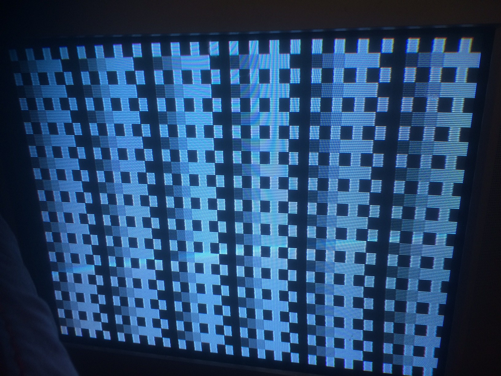
--- a/PIC12-T1.ASM
+++ b/PIC12-T1.ASM
@@ -8,8 +8,8 @@ LineN EQU 0x08 ; line counter
 TempN EQU 0x09 ; temporary counter

  movwf OSCCAL ; store factory calibration value
- movlw 7
- movwf Seven
+ movlw 0xC0
+ option
  goto loop
New screenshot with 8 shades of gray:![]()
It's patterns 1,2,3,4,5,6,7,0 (incf) and 1,6,1,6,1,6,1,6 (comf)
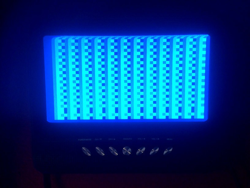
Also I reduced pull-up resistor (from GP4 to +5V) - now it's 480 Ohm (too small?):
![]()
-
1st run
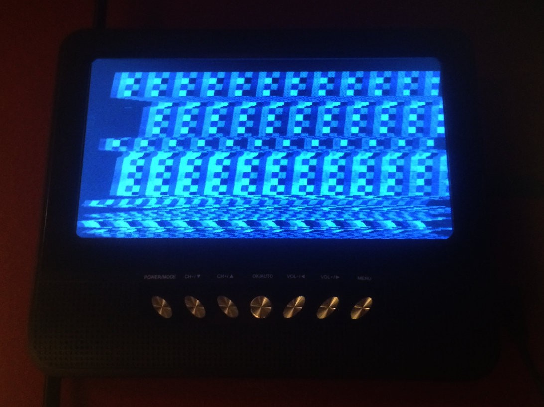
01/06/2017 at 04:36 • 0 commentsI connected 1.5 kOhm resistor to GP0, 680 Ohm to GP1, 330 Ohm to GP2 and 1K to GP4 (sync) - all of them connected together create analog VIDEO. Program for PIC12C508A is PIC12-T1.ASM (429 words or 643.5 bytes). Result:
Trying to see what is going on - probably just resistor values have to be corrected...![]()
UPDATE: After pulling-up GP4 with 2K resistor it's a little bit more stable:
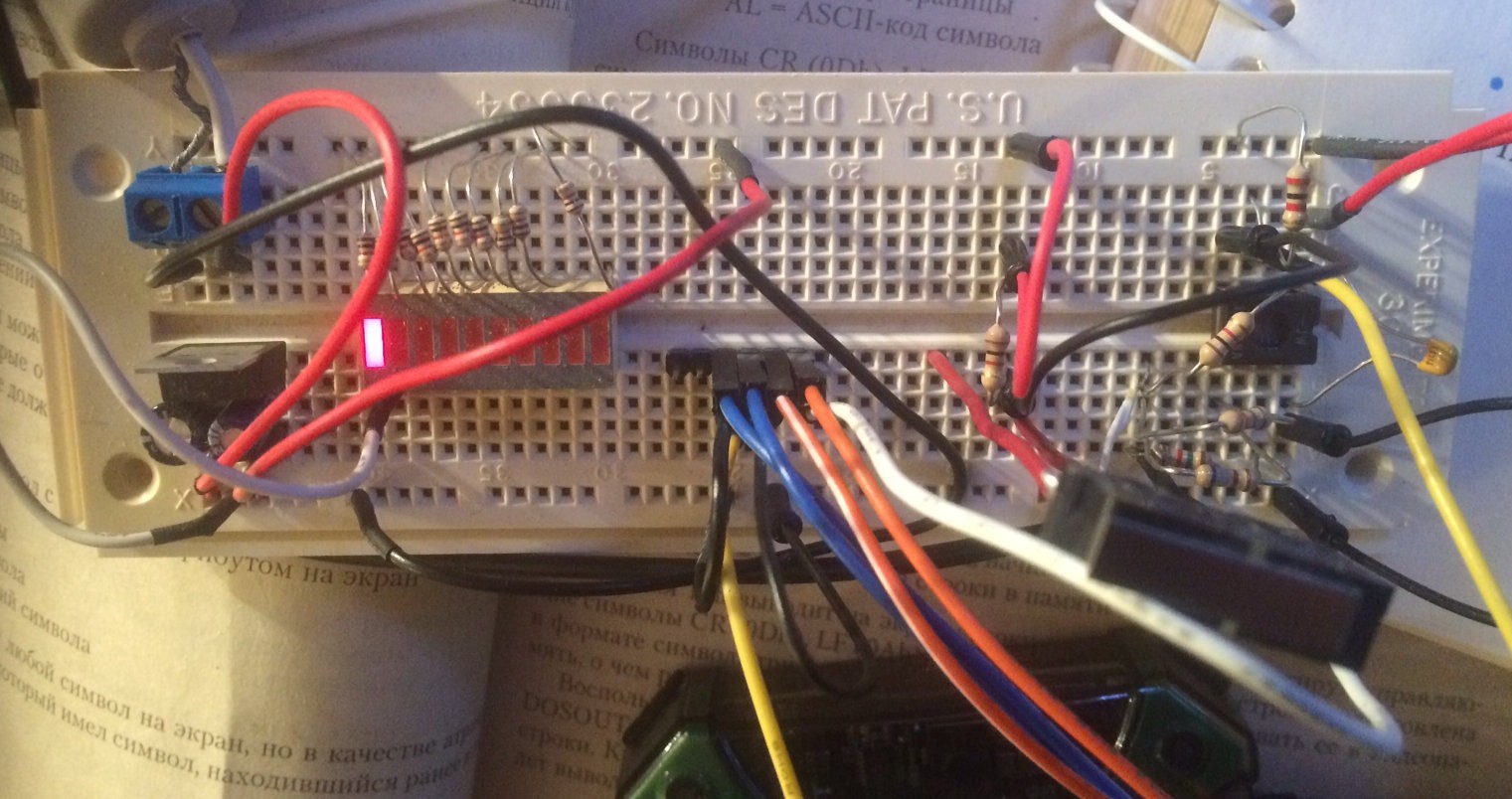
Test setup:
![]()
-
Line of the Raster
01/05/2017 at 06:05 • 0 commentsSo we will have 64 uS line where:
- 4 is blank before sync
- 5 is a sync
- 7 is blank after sync
- 48 is visible screenPIC12C508/509 don't have interrupts, so we will simply call Line(s) subprogram(s) multiple times to generate proper raster:
; call ; 2/2
Line:
 nop ; 1/3
 nop ; 1/4

 ; video 48 instructions /52
 ...

 clrf GPIO ; 1/53 -> video 48
 nop ; 1/54
 nop ; 1/55
 movlw 0x08 ; 1/56
 tris GPIO ; 1/57
 incf LineN,f ; 1/58 -> sync
 nop ; 1/59 -> sync
 nop ; 1/60 -> sync
 movlw 0x18 ; 1/61 -> sync
 tris GPIO ; 1/62 -> sync
 retlw 1 ; 2/64
For frame sync it will be special Line subprogram...
$1 entry to 1kB challenge
Let's use 1-dollar 8-pin PIC12C508A that has 512 words of program ROM (that is 768 bytes) and 25 bytes of data RAM...