 karen.soledad.quezada
-
13D printing
To manufacture the parts, a 3D printer is used, specifically the CR-10 printer, using the Cura 4.11 software with the following parameters:
- Layer Height: 0.2mm
- Nozzle: 0.4mm
- Tree supports with 60° overangle
- Horizontal expansion: -0.05mm
- Material: PLA
- Weight of material: 700 g
- Infill: 20%
The pieces corresponding to the bearings of the project, the rodtest piece is printed, so that the tolerances of the 6mm balls and the bearing tracks are adjusted, varying their horizontal expansion.
-
2Assembly of pieces
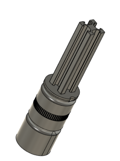
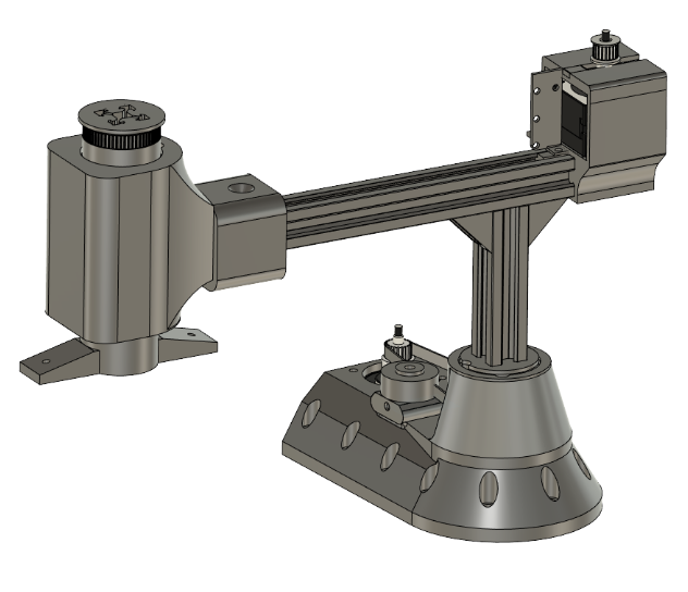
The assembly between the vslot profiles is carried out by means of localized blows normally to the section plane, in order to achieve a pressure joint without glue. The following image illustrates the assembly of the vertical bar that is the axis of the rotating base.
-
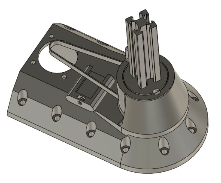
3Assembly of bearings
To assemble the bearings, the pieces are arranged in an aligned manner and the balls are inserted through the hole provided to load the bearing with balls. Also remembering to insert the closed band in the section arranged to achieve transmission with the shaft.
![]()
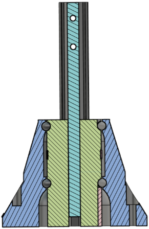
Performing the same procedure for the lower section.
![]()
In addition to a cover so that the balls cannot come out of the bearing. The second bar bearings can be seen below:
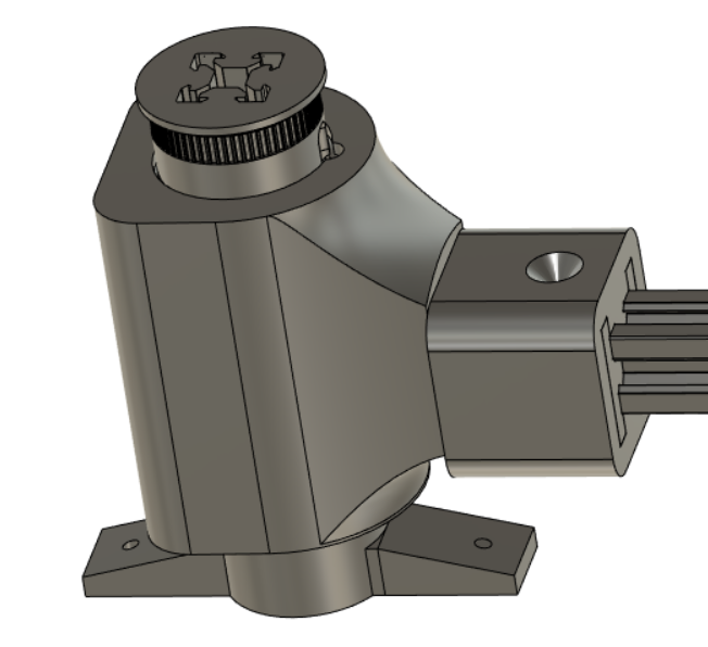
Then the bars are linked as you can see in the image:
-
4Linear axis assembly
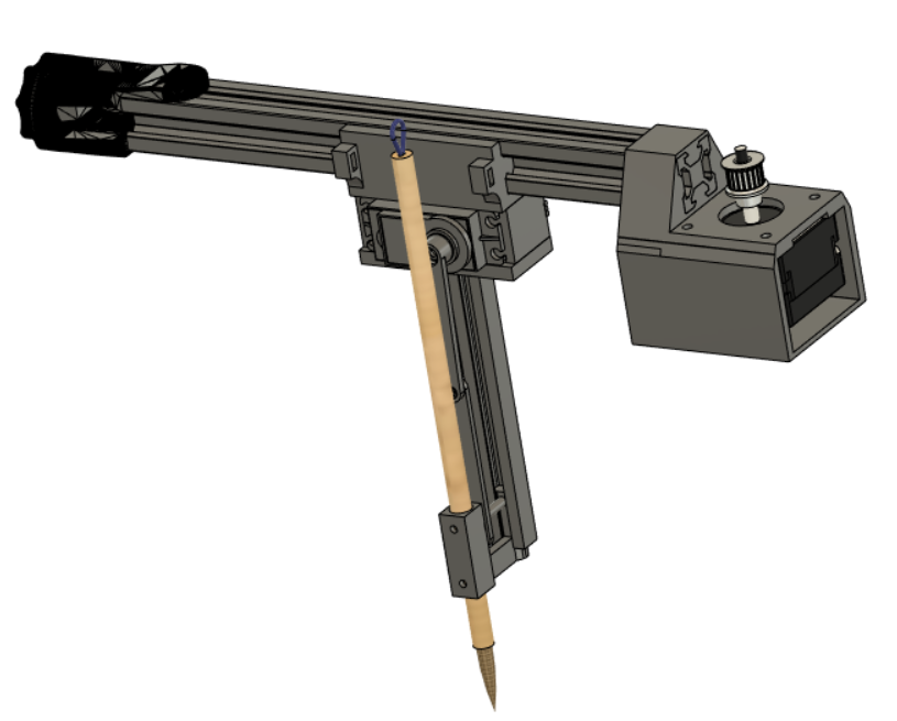
The assembly of the linear movement of the Scara can be seen in the following image, where there is the motor at one end of it and a tensioner on the other side, while between the ends there is a carriage that moves a set of servo and bench. Linear with a crank mechanism to achieve the vertical movement of the brush.
An open gt2 belt is used for the linear sliding of the servo carriage, which is affirmed according to the slots arranged in the horizontal of the servo.
-
5Final assembly
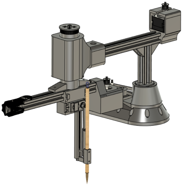
By assembling both bars of the Scara robot, a final set is obtained as can be seen in the image:
-
6Electrical system connection
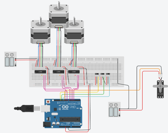
The connection of the electrical system can be illustrated according to the following image, where two power sources are used, one of 12v to feed the steppers and one of 5v to feed the servo.
The previous connection is illustrative, because all these connections are made by the cnc shield, saving many cables.
-
7Trajectory programming
In the first place, the .ino code is used, which allows the robot to be moved in certain degrees of tolerance, so that by means of serial commands, it is indicated the direction of movement and the motor to be activated, so that executes a counter in each of the variables to be controlled, except the servo. Once the desired position is reached, a command is entered to print the values that correspond to the steps that each motor must move. Then these positions obtained through the control variables are used to achieve a painting trajectory according to the kanji to be made. This is done considering that only straight lines are going to be made and they will be mainly along the linear axis that the robot has.
The home function is also added, which corresponds to the moment in which the 3 initial reference endstops of each one of the axes are activated, and a zero function, which leaves the robot straight with respect to the base.
The commands that are available are:
- "a": move motor q1 in 10 steps forwards
- "s": move motor q1 in 10 steps backwards
- "d": move motor q2 in 10 steps forwards
- "f": move motor q2 in 10 steps backwards
- "g": move motor q3 in 10 steps forwards
- "j": move motor q3 in 10 steps backwards
- "h": home function
- "k": zero function
- "A": run saved path
Prismatic Scara
A robotic manipulator based on a scara robot but adding two more linear degrees of freedom for the purpose of writing Chinese calligraphy
Discussions
Become a Hackaday.io Member
Create an account to leave a comment. Already have an account? Log In.