HOW IT WORKS
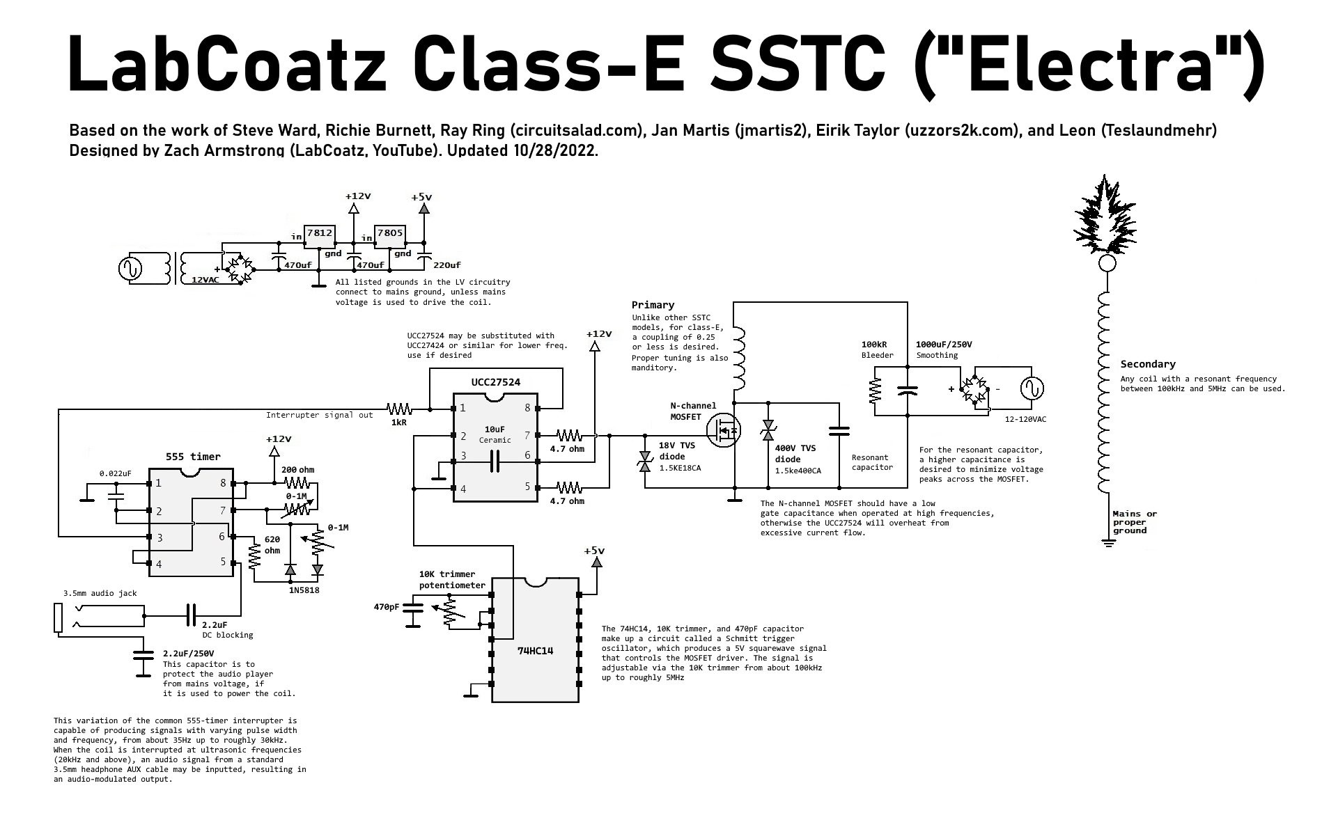
Above, you can see the schematic for this Tesla coil. At its core, this design is very similar to Steve Ward's class-E SSTC, but there are a few key changes. For one, the slower UCC37322 has been swapped out for the newer and faster UCC27524, and the old interrupter has been changed out for my own custom circuit, which was derived from the classic musical flyback driver.
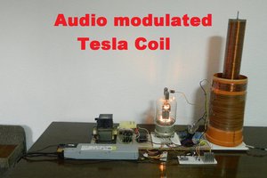
This new interrupter circuit has probably the widest range of any Tesla coil interrupter: its duty can be varied from 0 - 100%, and the pulse frequency can range from as low as 35Hz up to 35kHz. That's right: this Tesla coil can be interrupted ULTRASONICALLY, so the sparks have the silence of a CW flame, but with less power consumption! And with ultrasonic interruption comes the possibility of audio modulation. By feeding an audio signal from a standard 3.5mm headphone jack into the circuit, we can transform our Tesla coil into a miniature plasma speaker, with really crisp audio quality!
Another major change involves how this circuit produces its drive signal. Steve Ward's original circuit utilized an antenna for feedback, much like my previous coils. Sadly, this didn't seem to work in my circuit, so I had to use an oscillator. Most designs use fixed-frequency crystal oscillators, which are both difficult to set up and quite limiting (your secondary coil must be built to match the crystal's frequency almost perfectly). So instead, I went with a very simple (yet surprisingly reliable) adjustable oscillator that, to my knowledge, has never been tried in a Tesla coil before: the Schmitt trigger oscillator!
Here is how it works: an inverting Schmitt trigger (the 74HC14) is set up with a capacitor between its input and ground, and a variable resistor between its output and its input. When powered up, the input is "low" (0V), so the output goes "high" (5V). Some of the "high" output it directed back to the capacitor at the input through the resistor, and it begins to charge. Once the capacitor is charged to the trigger voltage, the input is perceived to be "high", and the Schmitt trigger sets its output "low". With the output "low", the capacitor bleeds off its energy through the resistor, and the cycle repeats. The on-and-off cycling of the Schmitt trigger's output produces a fairly clean squarewave that is ideal for our driver circuit! Furthermore, the cycling rate is determined by both the capacitance and the resistance, so using a trimmer potentiometer as the resistor allows us to have an oscillator with a tunable frequency!
The rest of the circuit is pretty straightforward: the signal from the Schmitt trigger oscillator goes to the UCC27524 gate driver, which amplifies the signal into a more beefy 12V squarewave. The two outputs of the UCC driver are put in parallel (two separate resistors are used instead of one to protect against internal shoot-through, as recommended by the manufacturer) and the signal is sent to the MOSFET, which switches the main power stored in the large electrolytic capacitor across the primary coil. If the Schmitt trigger oscillator's frequency matches the secondary coil's natural resonant frequency, the oscillating currents in the primary coil will excite the secondary coil with its magnetic field, and we get ourselves a nice high voltage display!
CLASS-E OPERATION
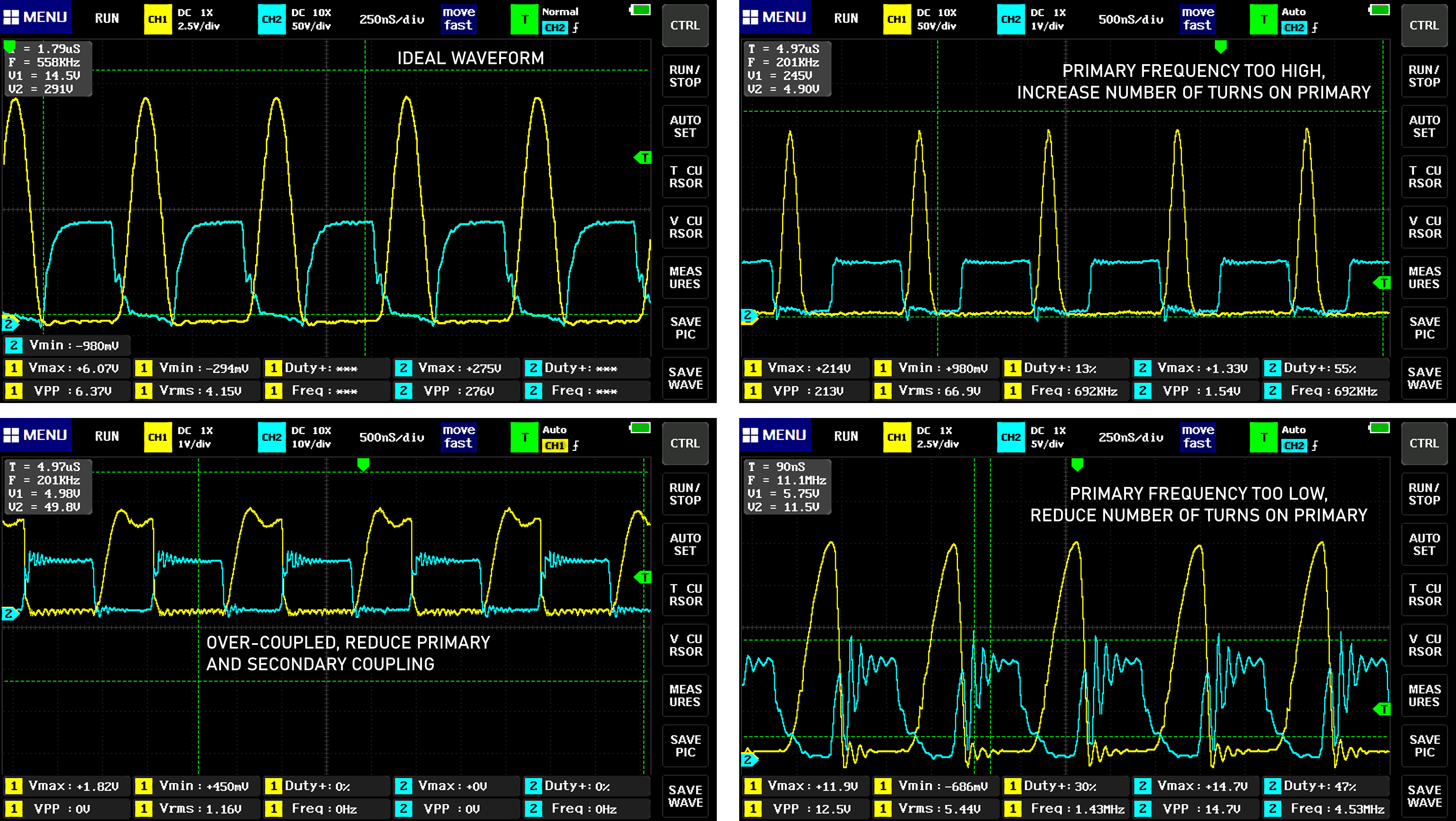
So what makes this a class-E coil and not just another MOSFET slayer exciter? Actually, only one component: a tuning capacitor. The capacitor placed between the MOSFET's drain and source forms a resonant circuit with the primary coil, and if this resonant circuit is tuned just right, the MOSFET will switch on and off when the voltage across it is zero. This is known as zero-voltage switching (ZVS, which also tends to coincide with zero-current switching, or ZCS), and it is the key to keeping the MOSFET stone-cold despite it having hundreds of watts pumped through it. ZVS also helps keep the MOSFET safe from voltage transients....
Read more » Zach Armstrong
 mircemk
 Marek Materzok