 davedarko
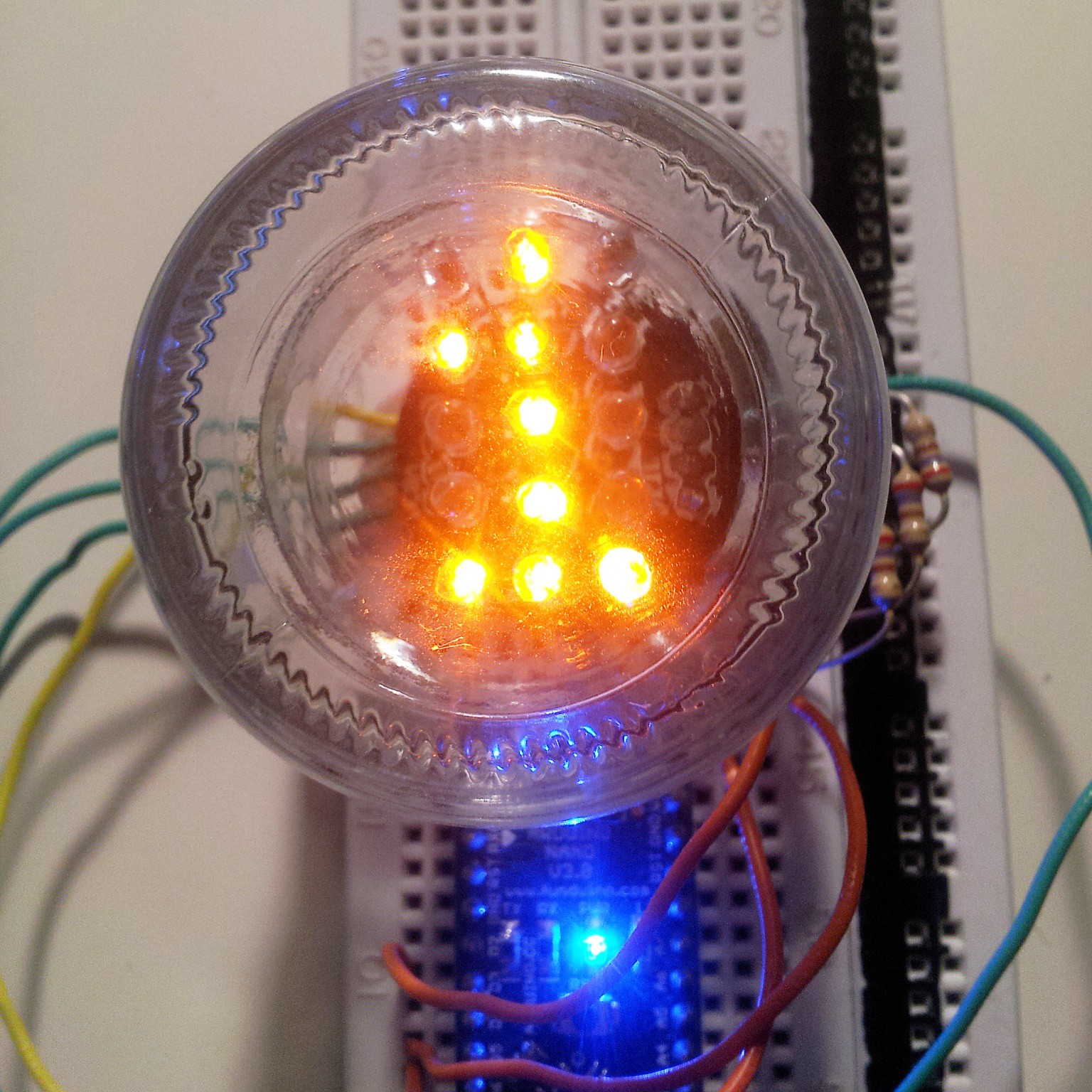
I soldered 15 LEDs today, and I soldered them backwards. I wonder how and why this is always happening to me, but I guess that is due to my laziness to check my own sketches... nevermind, some arduino code later I had this little mockup prepared. You can still see the board behind it, but as soon as the base plates arrive, it will be a lot darker in the background and the blue LEDs for the boarder will distract you from the background even more, I'm quite pleased with the outcome so far. The LEDs are actually glowing more orange than on this picture.
The LEDs I ordered as seen in the picture are orange but I may use amber colored LEDs I still have laying around. I previously ordered new LEDs because I had not enough for 6 displays but looking at the orange I'm not sure I'm satisfied. To be sure I should build a second one with the amber LEDs and compare them directly.
I'm still waiting for the control boards and the blue LEDs. After that I have to design and print the jar sockets
Discussions
Become a Hackaday.io Member
Create an account to leave a comment. Already have an account? Log In.
Are you sure? yes | no
The LEDs are still really bright and are a lot more orange than in this picture. I'm running them with a pwm on the column, but they only flicker a bit (scanning rows seems to be faster then the pwm cycles). But I may add some software pwm for the matrix later, when I see how they will behave when "driven" by the 74hc595. I'm skeptical since they aren't supposed to be used as a current source and/or sink and they're probably going to drop in voltage anyways. I tested some other orange LEDs setup with a 74hc595 but can't compare it two the arduino setup since I needed the cables elsewhere and pulled the breadboarded circuit apart. I guess I should get some more jumper cables.
Are you sure? yes | no