Johan Berglund
-
The basics of the code pt.2 - Switch Hook and pulses
12/12/2016 at 18:17 • 0 commentsNow this needed some more attention. The switch hook pin (SHK) of the QCX601 not only tells us if the receiver is on hook or not. Due to the way pulse dialing works, it also presents us with the pulses from the rotary dial. To keep track of everything that's happening on that pin, we have to do some timing work again.
With the receiver on hook SHK is LOW, and off hook SHK is HIGH, so pulses coming in will be SHK going low about 60 milliseconds for every pulse. If the time since the last pulse is more than 500 ms we know we just got a complete digit. For accuracy and immunity against false pulses we want 10 to 15 ms of debouncing, so that's another timing thing to the list. To know when we have a complete number, we assume that ten digits is a complete number (you can easily change this) and if the number is shorter, it will be dialed anyway if there are no new pulses for six seconds. Finally, if we put the receiver back on hook for two seconds or more, the dialing should be aborted and we should go back to the idle state. So, we have a bunch of timings to define...
#define tNewDig 500     // time since last SHK rising edge before counting for next digit
#define tHup 2000       // time since last SHK falling edge before hanging up/flushing number
#define tComplete 6000  // time since last SHK rising edge before starting call
#define tDebounce 15    // debounce time
And then the code being looped while in the number getting state:
// count groups of pulses on SHK (loop disconnect) until complete number
// if single digit, fetch stored number
// then make call

if (pulses && (unsigned long)(currentMillis - lastShkRise) > tNewDig) {
  // if there are pulses, check rising edge timer for complete digit timeout
  digit = pulses - 1; // one pulse is zero, ten pulses is nine (swedish system)
  // for systems where ten pulses is zero, use code below instead:
  // digit = pulses % 10;
  Serial.println(digit); // just for debug
  // add digit to number string
  number += (int)digit;
  digits++;
  pulses = 0;
}

if ((shkState == LOW) && (edge == 0)) {
  edge = 1;
} else if ((shkState == HIGH) && (edge == 1)) {
  pulses++;
  Serial.print(". "); // just for debug . . . . .
  edge = 0;
}

if ((digits && (shkState == HIGH) && ((unsigned long)(currentMillis - lastShkRise) > tComplete)) || digits == 10) {
  // if completed number (full 10 digits or timeout with at least one digit)
  // check if shortnumber/fave and then tell GSM board to initiate call
  if (digits == 1) getFave();
  Serial.print("Number complete, calling: ");
  Serial.println(number);
  number.toCharArray(numArray, 11);
  #if defined(GSM_MODULE)
  call.Call(numArray);
  #endif
  state = ACTIVE_CALL;
}
if ((shkState == LOW) && (unsigned long)(currentMillis - lastShkFall) > tHup) {
  // reciever on hook, flush everything and go to idle state
  flushNumber();
  Serial.println("On hook. Flushing everything. Going idle.");
  state = IDLE_WAIT;
}
Like that. As you can see, I also put in a speed dial function where single digit numbers are checked against a list with the getFave() function and replaced with complete numbers. Also, you can see the default state of the code is for use with Swedish phones where the dial goes from 0 to 9. That's the line saying...
digit = pulses - 1;Most likely you don't want that, so you should use this line instead...digit = pulses % 10;That % in there (modulo) makes the digit value the remainder when dividing the number of pulses by ten. Basically it's using wrap around to get 0 instead of 10. I stole this little gem, I admit that. Looks so much nicer than the if-based alternative, and I got smarter by looking the % thing up ;)As for the debouncing of SHK, it's done whatever state we are in, and it looks like this. The currentMillis used for all timings is set here too.
currentMillis = millis(); // get snapshot of time for debouncing and timing // read and debounce hook pin currentShkReading = digitalRead(shkPin); if (currentShkReading != lastShkReading) { // reset debouncing timer lastShkDebounce = currentMillis; } if ((unsigned long)(currentMillis - lastShkDebounce) > tDebounce) { // debounce done, set shk state to debounced value if changed if (shkState != currentShkReading) { shkState = currentShkReading; if (shkState == HIGH) { lastShkRise = millis(); } else { lastShkFall = millis(); } } } lastShkReading = currentShkReading; -
The basics of the code pt.1 - Bell Ring Control
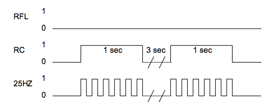
12/12/2016 at 12:11 • 0 commentsOk, so the main things I had to do dealing with the SLIC module was to have it create the ring signal, and to make the pulses and states of the switch hook pin control the actions of the phone. The ringing was the easier part, as it was pretty much exactly described in the QCX601 datasheet.
![]()
Early on I had decided to base my code on timings using the millis() function, so the "ringing" took this form, based on that diagram:
// Ringing interval
// How much time has passed, accounting for rollover with subtraction!
if ((unsigned long)(currentMillis - ringPreviousMillis) >= ringInterval) {
  digitalWrite (rcPin,1); // Ring
  // Use the snapshot to set track time until next event
  ringPreviousMillis = currentMillis;
}
if (digitalRead(rcPin) && ((unsigned long)(currentMillis - ringPreviousMillis) >= ringDuration)) {
    digitalWrite(rcPin, 0); // Silent after ring duration
}
// 25Hz oscillation
// How much time has passed, accounting for rollover with subtraction!
if ((unsigned long)(currentMillis - oscPreviousMillis) >= oscInterval) {
  // It's time to do something!
  if (digitalRead(rcPin)) {
    digitalWrite(hzPin, !digitalRead(hzPin)); // Toggle the 25Hz pin
  }
  // Use the snapshot to set track time until next event
  oscPreviousMillis = currentMillis;
}
The rflPin is set to be LOW all the time, and the timings are defined like this for typical Swedish ringing:#define oscInterval 20 #define ringInterval 6000 #define ringDuration 1200Basically, for every lap in the loop when in ringing state it does this...If it's time to sound the bell again, put the RC pin HIGH, then reset the time for this (wait 6 seconds until next go).
If the RC pin is HIGH, and it has been 1.2 seconds since it was put HIGH, set the RC pin LOW to stop ringing.
If it has been more than 20 ms since last toggle of the 25Hz pin, reset the time for this and toggle the 25Hz pin should the RC pin be HIGH.
(And then there are checks if we should stop all the ringing and go to some other state, of course.)
Cellular conversion of vintage rotary phone
GSM conversion for rotary phone, using Arduino Pro Mini with Atmega328, a QCX601 SLIC module and a SIM800 breakout board.