Bharbour
-
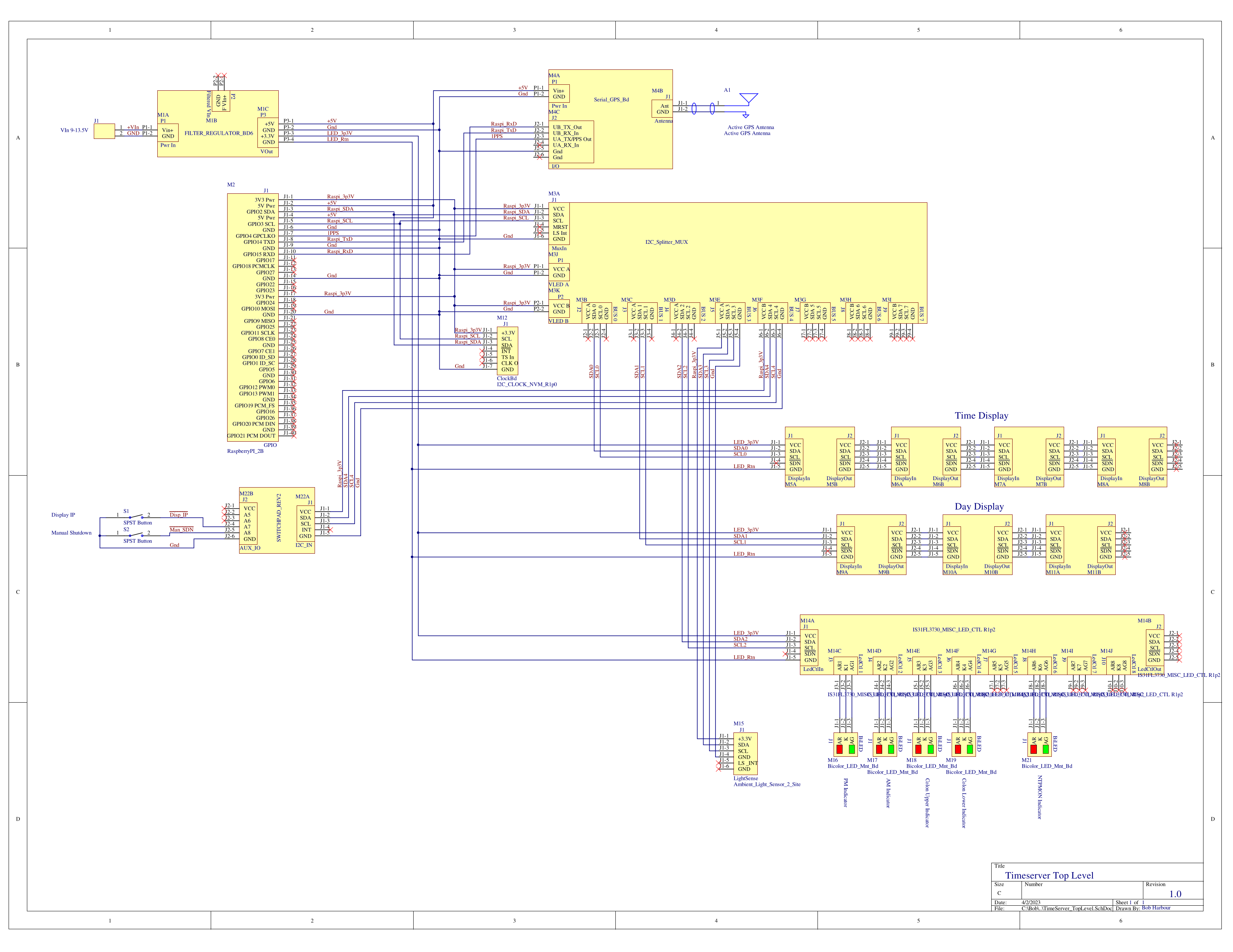
Top Level Schematic
03/26/2023 at 20:24 • 0 commentsI have been working out a style for drawing top level schematics with a PCB schematic capture package. After a fair amount of messing around, this is the resulting drawing of my Timeserver project.
![]()
Some things could use a little more work, but as a document, this works for me.
Each individual board is created as a component in my CAD system. Connectors on the board are implemented as "parts" in the same way that you would have two (or 3 if you separate power supply pins) "parts" in a dual OPAMP component. This allows flexibility in how you place the individual connectors on a drawing. The one thing it does not allow is compiling into a net list. Each connector has pins "1", "2", "3"... and this confuses my CAD system because it would not make sense for a dual OPAMP to use pin 1 in both "parts" (other than the power supply pins). The way around this would be to include the connector ID in the pin number. For example on connector J1, pin 1, a name of J1-1 would be a unique name and the CAD system would be fine with that. The down side of this method is that the pin numbers become long and take more space on the drawing.
The connectors are placed on the drawing and I have drawn a rectangle around each one to represent a board. It would not have to be done this way, it would be possible to scatter the connectors around the schematic in the same way that groups of signals are handled on schematics with large, complex IC's on them. I tend to like working with the connectors for a board gathered into one spot because it makes it easier when poking around with a scope probe to find the signal you are looking for. There is definitely a limit to how far this approach can be scaled though.
Wire colors would be nice too. I think I can attach colors as a property to wires, but I have not gotten that far yet.
I went back and edited the schematic library and the top level schematic. The end result is fine, and now it compiles to produce a net list. Top level schematics tend to be large drawings anyway, so the change is not a problem. Being that the purpose of this is to establish the method and start building a library of the PCBs that I have designed, I want to get the best result that I can.
Has anybody else got a method for drawing top level system schematics and wiring harnesses that works?
-
Raspi RAM Overlay File System Startup issue.
02/08/2023 at 14:12 • 0 commentsSince the Raspi2 runs out of a uSD card, minimizing writes seems like a good thing for long term reliability. The version of Raspi OS that I am using, offers "RAM Overlay Root File System" as an option on the raspi-config program. Reading on this indicates that the uSD card is marked read only and a RAM file system accepts the write data, making it non-persistant over resets or power cycles.
Since the Raspi2B does not have a battery backed real time clock to fetch clock time from at start up, it appears to take the real time from somewhere in the file system, approximating the time that the system shut down. This gets into trouble with the RAM Overlay File System, because the time and date that it fetches looks to be the time and date that the system was changed over to run the RAM Overlay File System instead of the last shutdown time.
Yesterday, we had a power line drop out for a few seconds. It was long enough to cause the Raspi2B in the time server to re-boot. After the re-boot, the ntpd daemon refused to stay connected to the GPS and PPS time sources.
When ntpd starts up, it looks at the system time and if it differs too much from the GPS time, it stops listening to the GPS. There is a command line option ( -g) that looks like it should force the system time to match the GPS time, even if the difference is large. The man page on ntpd indicates that this large jump can only occur once. It seems like this should solve the issue of the startup time, but it appears not to be working. Maybe the GPS system had not recovered a 3D fix before the ntpd daemon tried to do the one-time jump, don't know yet. If the ntpd daemon runs for 7 or 8 hours without access to the GPS or PPS time sources (peers), it shuts down. When I noticed the issue with the real time being hours out of sync and ntpd not listening to the GPS, ntpd was still running. I manually set the system time with the date command, and ntpd immediately hooked up with the PPS source again and has been running fine since.
It's possible that a battery backed real time clock is the answer. It seems like there should be a simpler answer.
2/12/2023 I think I dodged a bullet on this one. I have some little clock boards with a PCF2127 clock chip, and a battery (as well as an un-needed EEPROM chip) that I designed a few years ago for another project. It turns out that Raspi OS already has drivers for that clock chip included in the distribution. I set it up on my test platform and it works just fine. It also insures that the system clock is very close to GPS time at startup because those PCF2127 clock chips are quite accurate.
I considered writing a piece of code that will read time out of the GPS data stream and just force the system clock to that value at startup. There are a couple of problems beyond gracelessness with this approach. The amount of time that a GPS unit takes to get a fix can be pretty variable, depending on the environment. It can be up to a minute or so in extremely low signal environments and I don't want to whack the time setting that late in the boot process. Also, the effect on ntpd of doing that are unknown, by me anyway. This box already has a bunch of boards in it, one more will hardly be noticable.
2/14/2023 The ntp server program ntpd is a large, complex piece of code. I looked through the documentation to see if there was more information on the behavior of the -g option to see if there was an obvious reason that it was not setting the time at startup and could not find one. Resorting to the source code, I followed the track of the -g (force_time_step) option in from the command line parser. It was not obvious why the time step was not doing what I expected.

Mounting for clock board with easily accessible battery There is a place to mount the new clock board in a place where it is easy to access the battery for later changes.
-
Problems with ntpd shutting down
01/19/2023 at 22:09 • 1 comment1/19/2023 Several days into the testing on this box, I am finding that the ntpd time server daemon is disconnecting from the GPS and then 7 hours later, it shuts down. I am still isolating the problem. The bare GPS NMEA and 1pps interface is done via the gpsd daemon. The ntpd daemon interfaces with the gpsd daemon through a shared memory block.
I have used ntpd in the distant past, and it seems reliable enough. It is pretty complex and the configuration for it is definitely not trivial. In prior applications, I had it talking directly with the GPS modules.
The Trimble Copernicus II GPS modules have been working well for me in several other applications for years. This is a new board from an old design, so It's possible that the GPS is having problems, but that seems less likely.
The gpsd daemon is a new one for me and it does not seem to be doing anything that I really need in this application. My first step is setting up a test platform that has ntpd talking directly with the GPS and removing gpsd.
I just got the hardware and software together to test this idea. Now it is time to wait and see how it goes.
If the problem is not solved, I will swap the GPS module with a new design. The Trimble Copernicus II modules are not made anymore and I could not find any around from a credible source at a reasonable price. ST has a new line of low cost GPS modules called Teseo LIV3 and I put together a small breakout board for them before the holidays.
It is possible that the problem is in the configuration of ntpd, and I am going to leave that one for last because it is going to be the most difficult one to pursue.
1/26/2023 I am not ready to declare victory on this one, but I have gotten 6 days of operation from ntpd without a shutdown. Previously, I was getting a few hours up to 2 1/2 days before ntpd disconnected from the gps and pps sources. I swapped the Trimble GPS module from my test platform into the box and made the configuration changes necessary to disable gpsd and change ntpd over to use the Trimble TSIP protocol instead of NMEA.
I added another bicolor LED and plugged it into an unused socket on the misc LED controller board to use as an ntpd status indicator. I wrote the code to exec the ntpq tool and parse the output to determine if ntpd was still connected to the gps and pps sources and added a threshold on the jitter set to 1.0 mS. If the ntpd daemon is shut down, the status LED shows red. If ntpd has disconnected from the gps and pps sources, the LED will show yellow and if the jitter values are > 1.0mS, the LED will show green. If everything is good, the LED is off. This code runs periodically (every 2 minutes right now) and updates the LED as described. This status indicator was added so that I don't have to power up another machine to check the ntpd health, I can just look for the LED.
At some point, I will re-configure the GPS module that I pulled out and put it on the test platform to test the GPS module. This is just sort of a sanity thing, I would like to know for sure that the problem was not the hardware. That sounds like a thing for another day though.
The system is running on the box with the display now, for some longer term testing.
1/29/2023 Yesterday, at about 02:00, I noticed that the ntpd status LED was showing that it could not communicate with ntpd. Testing manually, ntpd was fine and there was nothing in the logs to indicate that it had a problem. The way the monitor is coded, the LED shows red if it could not communicate with the daemon, so if the monitor had a problem, it would show red also. Thinking about the problem (instead of sleeping), it occurred to me that the monitor had been running about 36 hours when it stopped working. With the monitor running once, every 2 minutes, that is around 1000 iterations, which is suspiciously close to the max number of file descriptors allowed on a process.
The way that I coded the monitor, upon requesting status, a new process is forked off, and a pipe allocated to ship the data from the child process back to the parent process. The stdout file descriptor is replaced with the write end of the pipe in the child process using a dup2 () call. The child process exec's the ntpq command to get the status from ntpd, and the parent process (my monitor code) reads the ntpq stdout data from the read end of the pipe. When the read is complete, the pipe is closed which should return the file descriptor to the OS. After the dup2() call, it is necessary to close the both the read and the remaining write descriptors for the pipe in the child process and the write end of the pipe in the parent process or the descriptors will not get returned to the OS when the child process exits.
It turned out that I had forgotten to close the write end of the pipe after the dup2() call in the child process, and a new file descriptor was getting allocated each time it was called. This was visible because the file descriptor value was incrementing each time the monitor was called. After adding the close on the write file descriptor in the child process, the incrementing stopped and the file descriptor has the same value each run as it should.
The ntpd daemon ran through all the debug and testing with no issues.
1/30 After 48 hours of operation, the monitor is still running fine, as is ntpd. Good news on both fronts.
2/8 Ntpd ran for over a week with no issues, I think that this issue is solved. The ntpd monitor that I added to the LED time display system is working fine.
GPS Network Time Server
A GPS Disciplined Network Time Server with a Local Display