-
1Print the parts
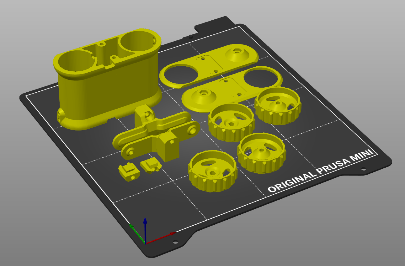
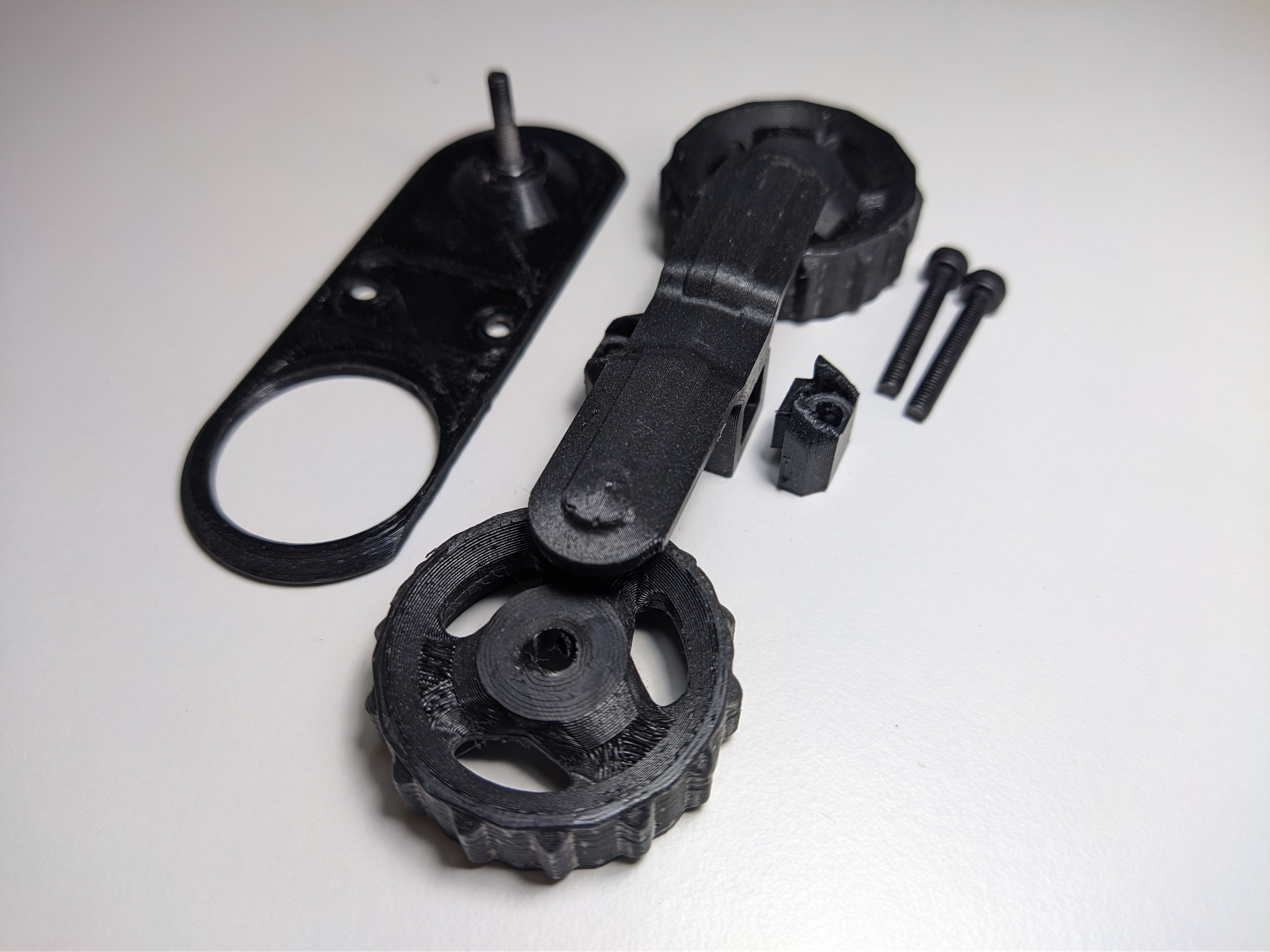
These are all the parts, excluding the 52 tread pieces (of which it is recommend are printed sequentially, in batches). All parts are designed to be printed without supports. I uploaded the whole thing as an STL if you want to make one yourself!
I have shown all the main parts in a single print here, but usually I would print most of them individually, to reduce stringing and other messiness between parts. The wheels and main body piece, especially.
![]()
-
2Assemble the main body
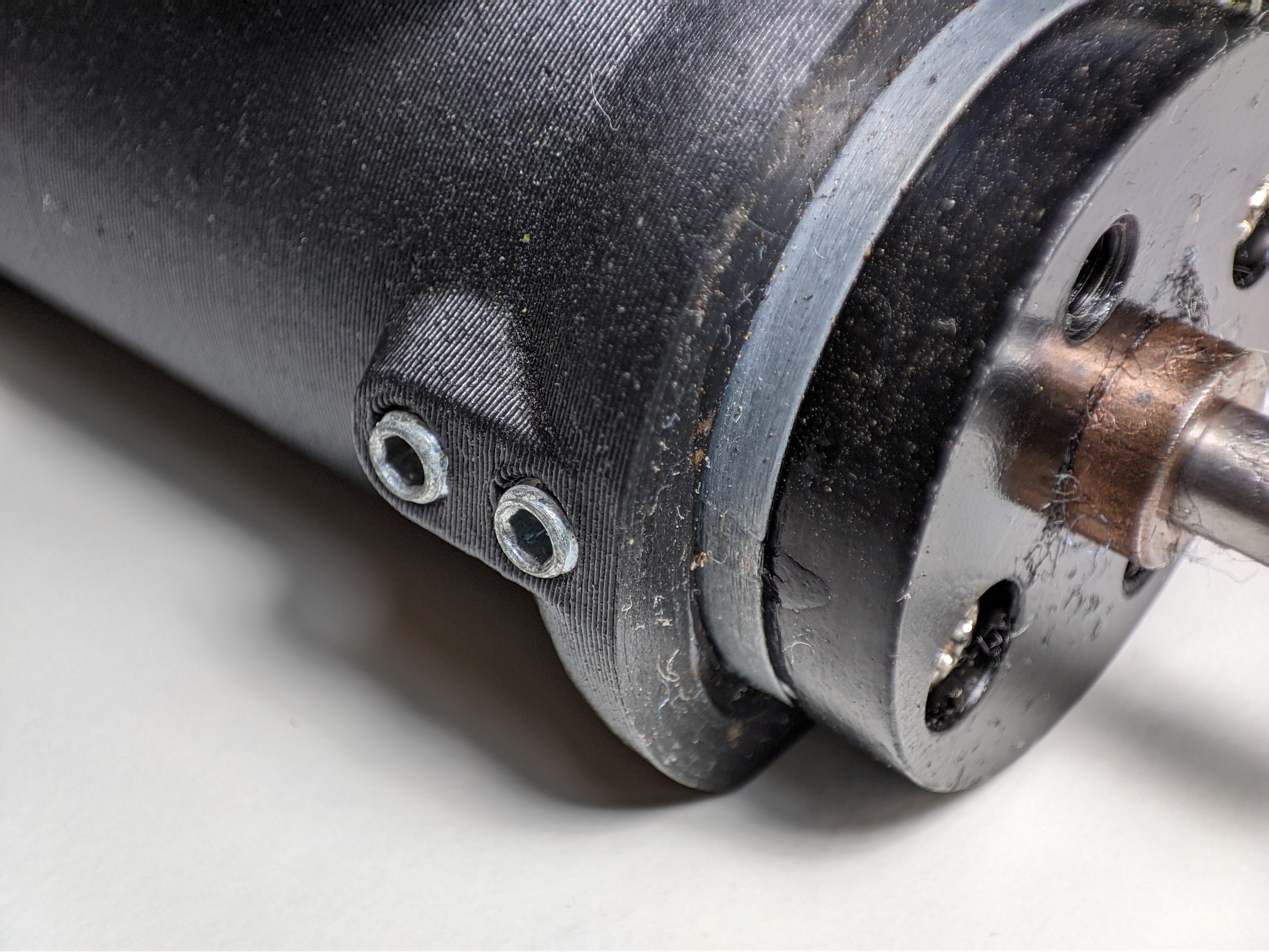
Put the motors in and fix into place with ~4mm M3 screws and nuts, grub screws are neat but not required*
It is deliberately designed for the motors to stick out of the side with the output shaft, and sit flush on the other side. The motors are an extremely tight fit, I apologise if yours do not fit. Pls let me know if you have any issues with this.
![]()
![]()
*Uhmm... so I have to confess something. The grub screws, no matter how cute they are, aren't actually adequate for holding the motor in place, especially since they are threaded into plastic and they slip super easily. Sooo... a little secret between you and me, I may or may not have super-glued the motors in-place. Hush, don't tell anyone!Now fixed! -
3Solder up electronics
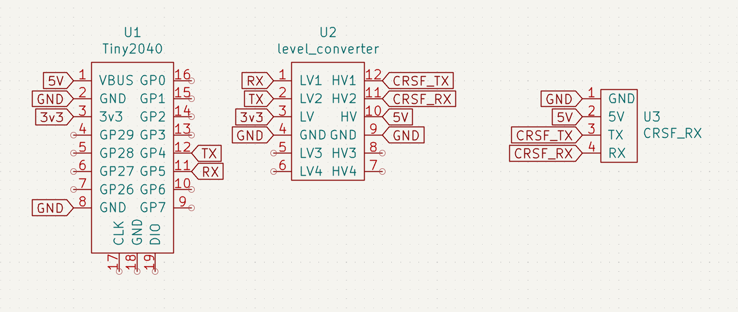
I have included a diagram showing to show how to connect the ELRS reciever. The rest of the electronics (power supply, motor drivers and FPV video system) can be done however you want, with any generic components, as long as they fit. Read the 'details' section if you want to know how I did it.
Thank you to the CRSF Joystick project on Github, which helped me interface the CRSF reciever with a microcontroller (and from which I stole this diagram)
**I have been informed that the level converter is not necessary with an ELRS reciever, so just don't bother with it XD**
![]()
-
4Program microcontroller
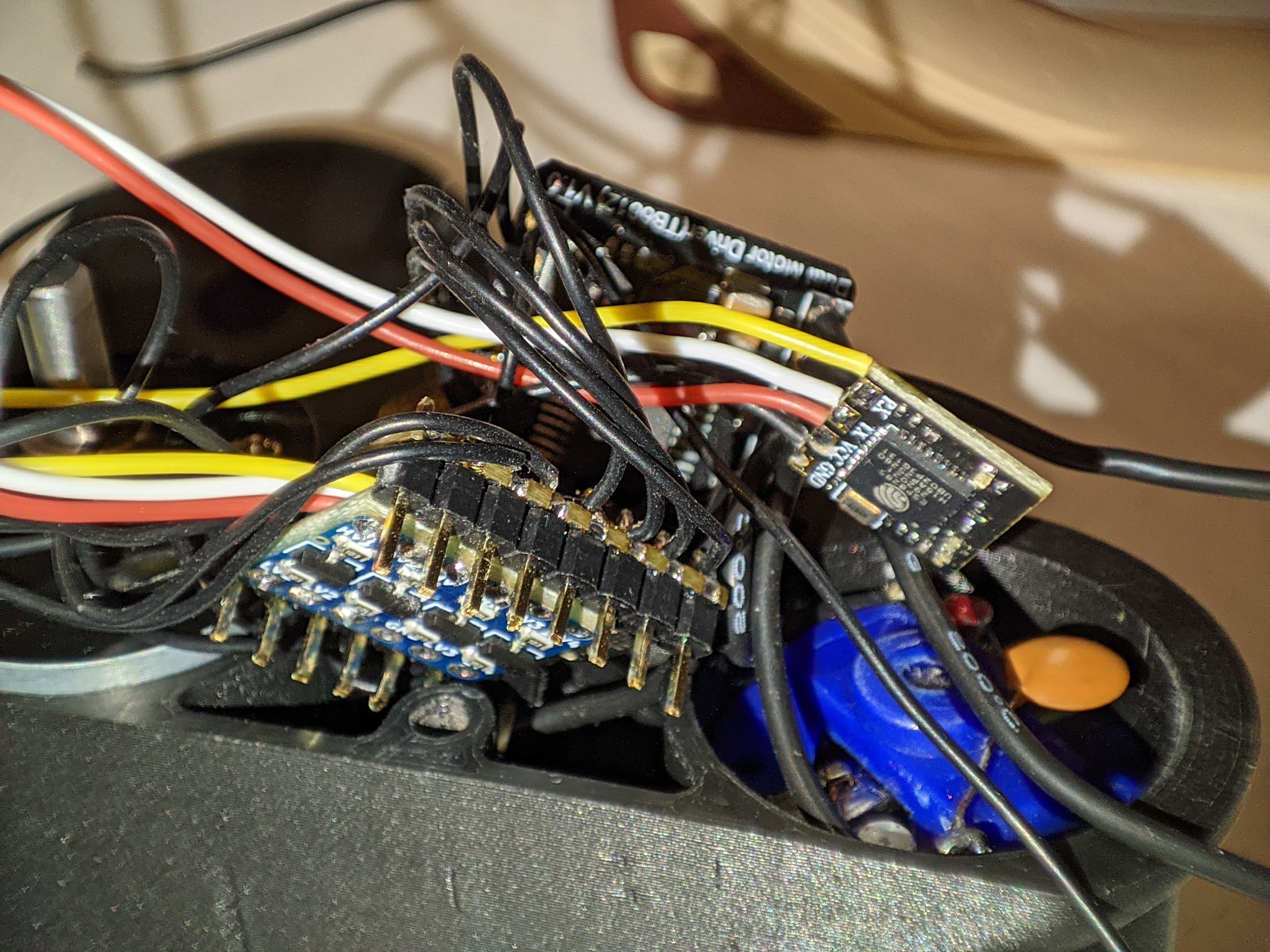
I have uploaded the code into the files section.
Credit goes to CRServoF on Github, for providing the code that allows Arduino microcontrollers to interface with CRSF receivers!
Also, ignore the Noctua fan in the background hahaha
![]()
-
5Assemble the rest of the body
These are the parts that are required on each side, including 16mm M3 screws and nuts for the two idler wheels. All the parts are held together by four 25mm M3 screws, which are simply threaded into the holes in the main body piece.
![]()
-
6Assemble the treads and place onto wheels
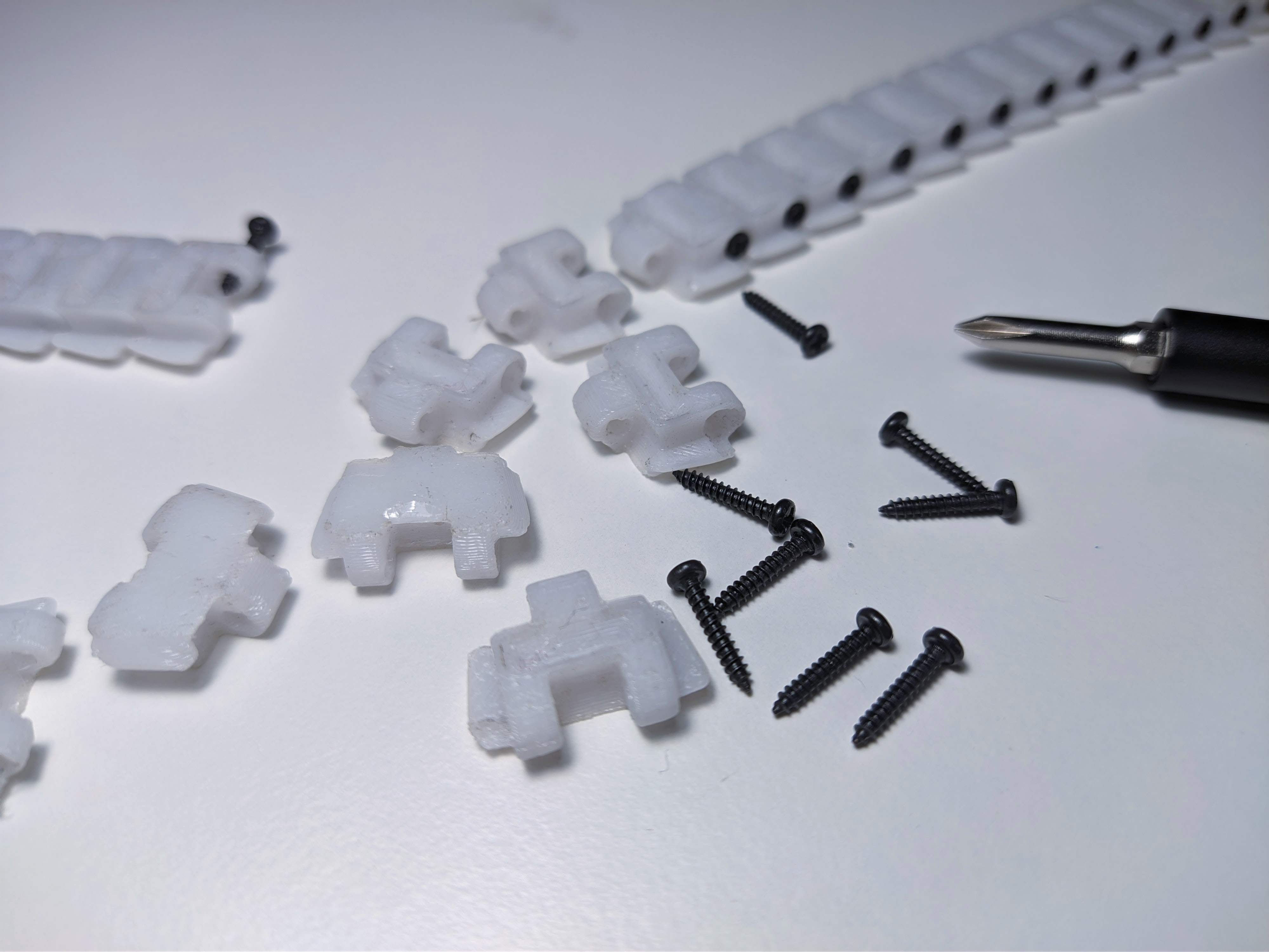
26 tread pieces per side, held together with 10mm M1.7 self tapping screws. Make two loops, snap them onto the wheels, and you're done!
![]()
-
7Final assembly
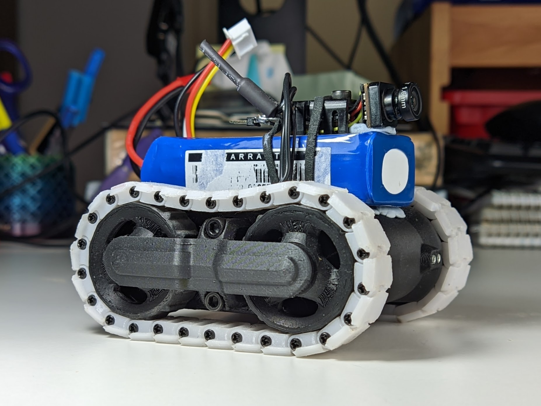
Blu-tack the battery and camera and body together like an absolute pro! Also rubber band the other stuff together!
![]()
-
8DONE
Enjoy! Please let me know if you end up making something from this design, I'd love to see!
Mini FPV Speed Tank
A small, fully 3D printed tank, designed with a focus on compactness and performance
 Tobias


Discussions
Become a Hackaday.io Member
Create an account to leave a comment. Already have an account? Log In.