 tinkerzone
So the case handily had two 2mm x 4mm slots for led indicators. I started by going through the led box to see if I had any rectangular leds-and I found a yellow led and a green led both 5mm. Filing down the edges of both by 1mm left me with-something pretty ugly tbh. I decided to scrap the rectangular leds.
Next step was to see what else I had: the large collection of 3mm leds I had would look really ugly in those slots. Similarly the 5mms would require more drilling, and I don't think would look terribly good either.
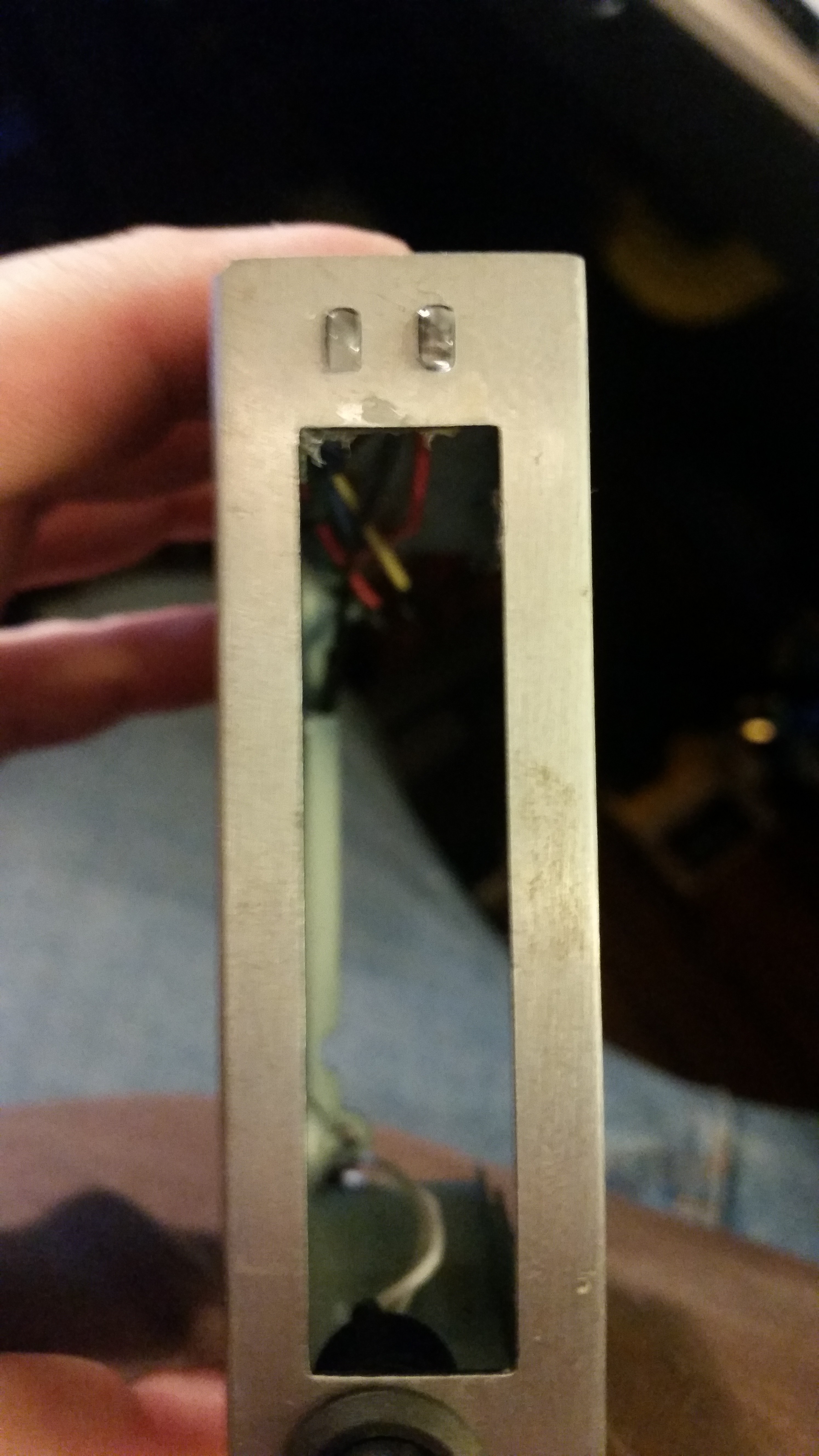
So i hatched the following plan. The top led is a blue 5mm which has had two sodes demelled off to form a rectangular box shape. Then the third side had 1mm dremelled off leaving a funky modern curve.
The second slot I decided should be a status indicator led of some point. I thought about mirroring the activity led on the pi zero, but soldering that is way too small for my eyes. So I grabbed a common anode RGB led, dremelled before and it fitted beautiful.
The next stage was to test the RGB led. Note: not all rgb leds are made equally. Often one colour will shine brighter for the same amount of current. After a series of tests to see how the colours mixed, the final decision was to feed Red via a 1k ohm resistor, with the G and B leds being feed through 3k ohm resistors. Your values will probably be different. Test for yourself.
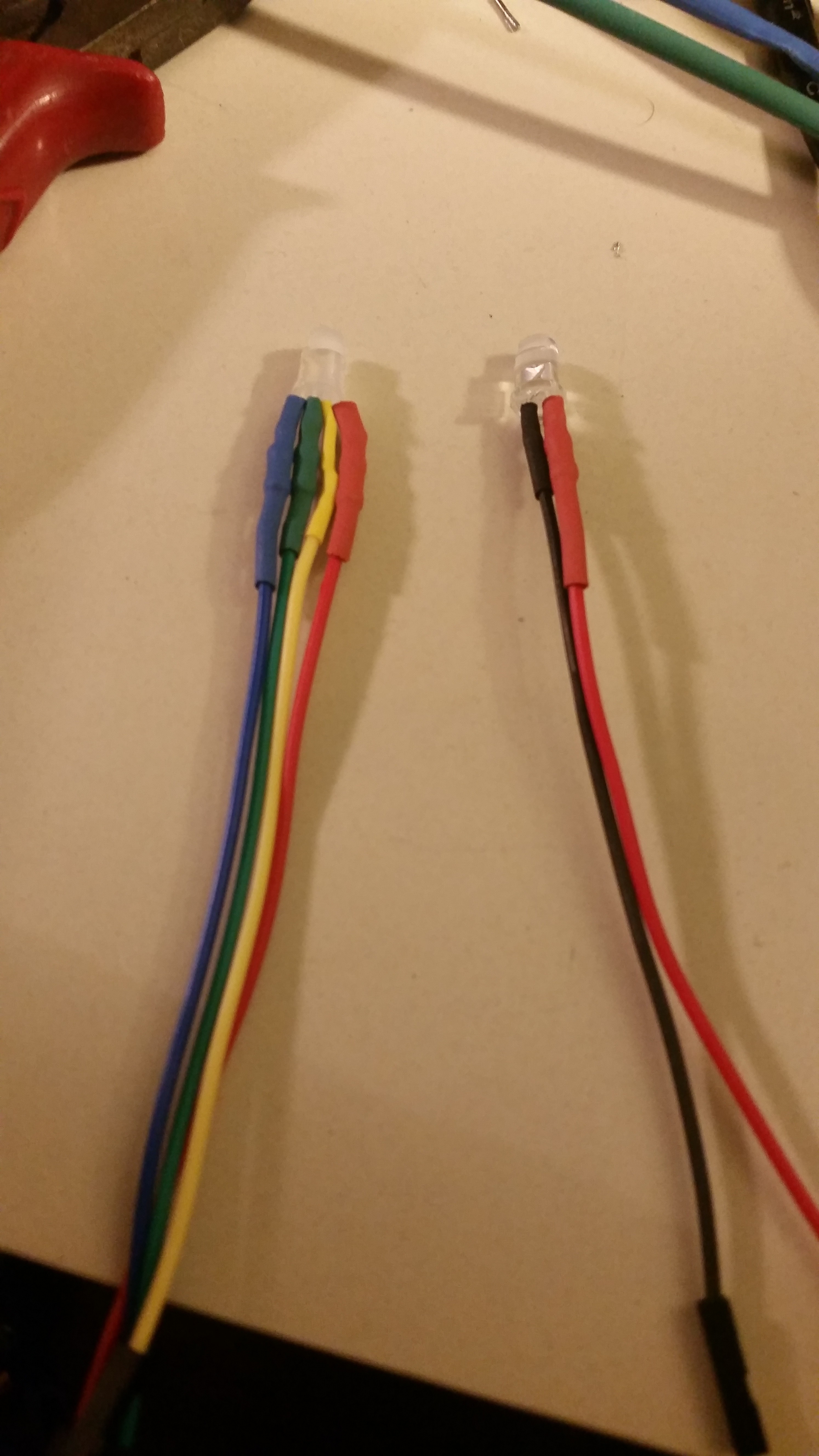
Given that these are to be plugged in to the pi zero board, the leds were soldered in-line with the resistors before being covered up with heatshrink. Dupont connectors on the end, obvs. As the leds are being supplied with 3.3v, I would have usually made the anode green (to match the atx wiring code: 12v yellow, 5v red, 3.3v green, but as it was an rgb led, I decided to wire each rgb pin with it's matching colour and used yellow for the common cathode. The blue power led is being driven by 5v, so was given a red anode lead with a 2.2k resistor in series.
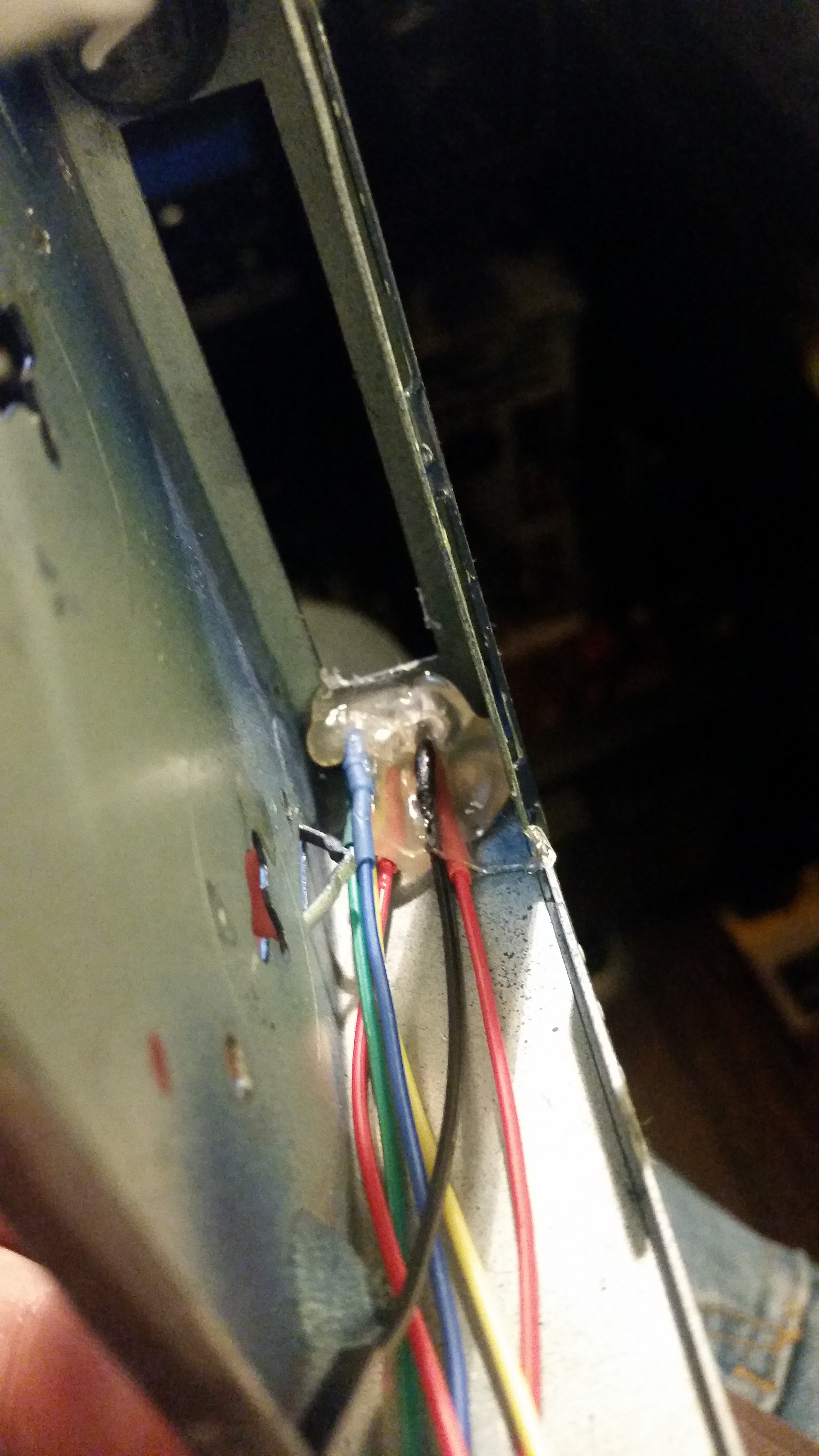
They were mounted the old fashioned way - with lots and lots of hot glue. A neat trick to mould the hot glue is to wet your finger and push the hot glue into shape. Be careful, and don't blame me if you get burnt.
Discussions
Become a Hackaday.io Member
Create an account to leave a comment. Already have an account? Log In.