 Arya
AryaATTiny85
Measurements and preparations:
- IC dimensions (with pins) - 0.36x0.30in
- IC body dimensions - 0.36x0.23in
- Dimensions between pin centers - 0.1in
The SVG we'll need to draw will be a little larger though to look nice and be perfectly aligned with the grid. Let's say pin rectangle height will be 0.035.
Modifications:
- IC dimensions (with pins): add 0.04 to width amd height
- IC body dimensions - multiply pin rectangle height by 2 and subtract that from IC body height, body width stays the same
Resulting dimensions for ATtiny85:
- IC dimensions (with pins) - 0.38x0.34in
- IC body dimensions - 0.38x0.27in
Inkscape usage
Save your SVGs as "Plain SVG" (File->Save as...) This will prevent Inkscape from inserting unnecessary tags, you just have to remember to do it each time you save your changes.
Changing canvas dimensions: New document, Page-> Document Properties, set dimensions and units inches.
How to dimension things: Object->Transform->Scale (might need to uncheck "proportional"), set dimensions to
How to center and align relative to canvas/other things: Object->Align and Distribute, it has various icons, Align section has the ones we need.
How to color things: Object->Fill and Stroke, stroke is object outline.
How to ID things: Object->Object Properties, the ID field.
How to group things: select things you want to group and Object->Group.
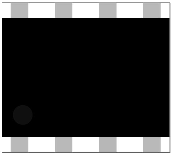
Drawing the IC body

Draw a rectangle, dimension to 0.38x0.27in. Align to vertical/horizontal canvas center. Fill with solid black. Draw a circle to mark the first IC pin, and make it 1c1c1c grey.
Drawing the IC pins
 Draw grey rectangles. Height is 0.035 as we defined in the beginning, width is about the same, better if it's an even number - like 0.04. Y coordinate is simple to determine - just vertical align top pins to top canvas line, and bottom pins to bottom canvas line. X coordinate calculation:
- They'll be different by 0.1 - that's the pin spacing. The spacing between pins will be 0.3in long, so we have 0.08in left from both sides, thus 0.04in from top left corner to top left pin center
- X coordinates are taken from bottom left corner of pin rectangle, so subtract half of pin length from that topleft pin center coordinate we got. We get 0.04-(0.04/2) = 0.02.
- Thus, pin coordinates start from 0.02. We get 0.02, 0.12, 0.22 and 0.32 - that's for both top and bottom rows.
Finishing touches - text and IDs
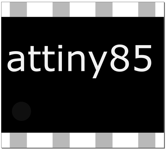
Place some text where you want, adjust the font size till it fits right.
Give IDs to your pins - they should look like "connectorXpin", for us X is a number from 0 to 7.
Select all, group it and ID it as "breadboard".
Discussions
Become a Hackaday.io Member
Create an account to leave a comment. Already have an account? Log In.
You should really enable a grid in Inkscape -- that will make your life much easier! (You can find grids tab in the document properties.)
Are you sure? yes | no
Will try it - especially now that I'm writing the PCB footprint section =) It won't be useful if it doesn't snap to grid, though.
Are you sure? yes | no