1. Hardware set-up
Soldering all necessary connections is a little tricky because the small SMD board is not really prototype friendly. So either using some sort of adaptor, or soldering very carefully with fine wire and a fine soldering tip.
Used pins (RN4870 variant):
- Pin 2 - GND (from MCU)
- Pin 4 - VBAT (3.3V) (from MCU)
- Pin 23 - UART_TX (to UART_RX MCU)
- Pin 22 - UART_RX (to UART_TX MCU)
- (optional) Pin 30 - P0_2/LED (to 100+240 Ohm resistors and red LED)
- (optional) Pin 26 - UART RX Indication
For the RN4870U variant there is an antenna connection on Pin 30 (I soldered for my first tries just a makeshift antenna).
Baud rate e.g. 115200 (default); UART settings documented in the User's Guide, chapter 1.4.
2. BLE Scanner App
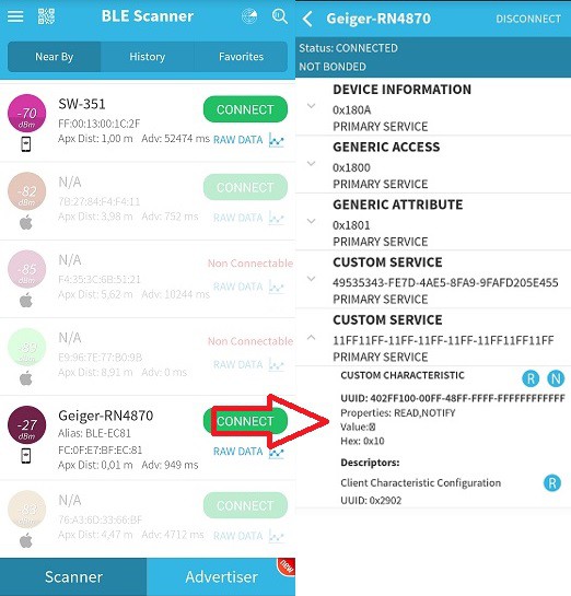
After the hardware has been set up the device and the quite peculiar BLE hierarchy should appear in the BLE Scanner App.
Screenshot on the right shows an already implemented private service UUID, beside the Transparent UART Service UUID.
(name of the device can be customized as a matter of course).
3. BLE module set-up
It is straightforward ASCII command communication with a device capable of communicating on the serial port (e.g. tool "minicom" on the Raspberry Pi), so I won't bother writing much about it.
E.g. in command mode (instigated with string "$$$") I can send "GNR\r" (or "GNR\r\n", doesn't matter) to the module, i.e. getting the name of the connected peer device. "V\r" would fetch the firmware version.
Important are commands such as "PS,(...)\r" or "PC,(...)\r", which are setting up Private Services and Private Characteristics (see User's Guide for details).
Example screenshot (note the characteristic UUID "handle" value printed on second position in the second line after the "LS\r" command: 0412):
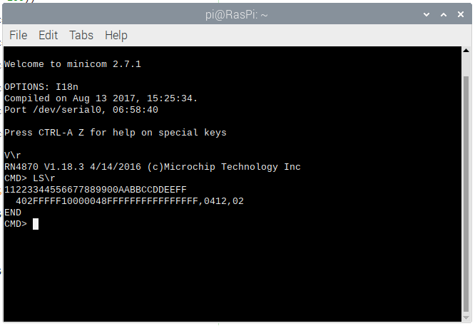
Configuring the device has to be carried out only once essentially. A (subsequently connected) MCU has just to know about the value of the "handle" to access the characteristic via its properties (e.g. write).
4. Demo Video
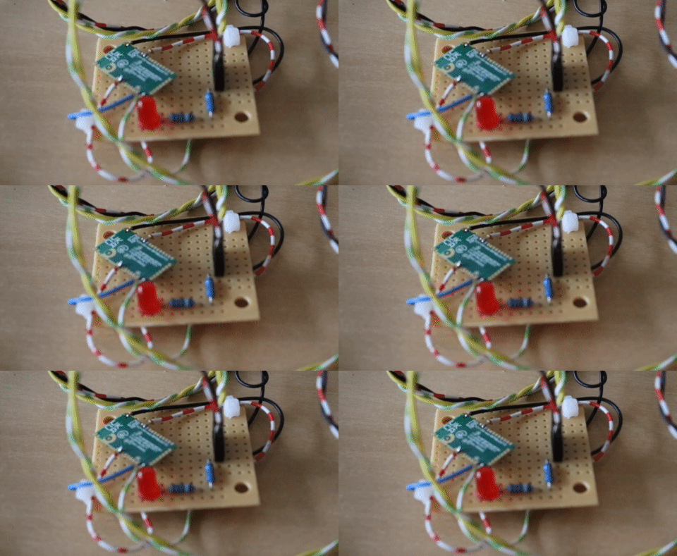
In German, English subtitles available.
 Florian Wilhelm Dirnberger
 rawe
rawe
 Paul DeCarlo
 Akshay Jain
 Sylwester