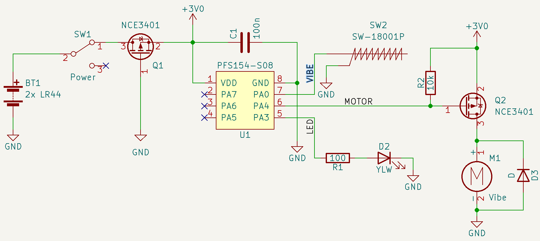
Nothing complicated about the schematic. A few things to point out about why I chose the parts I did.
- First I am using only components that I have on hand, I did purchase the SW-18001P vibration switch but everything else is what I can find in my stash or is reused from the original toy components.
- I use a P-channel MOSFET for reverse polarity protection because it introduces the lowest voltage drop. A shottky diode would be about 0.2V. The datasheet for the NCE3401 does not directly show what the Rdson at currents lower the 1A would be but extrapolating it looks to be around 75mΩ. At the maximum current draw of this circuit of 51mA that would be a voltage drop of 3.8mV. I will measure this when I build up a circuit to confirm.
- To reduce BOM count I am using the same P-channel MOSFET that is used for reverse polarity protection to also switch the rumble motor. I could just as easily use a N-channel or NPN transistor.
- I have been playing around with the Padauk PFS154-S08 for the last few weeks so I would like to use it in a project. This microcontroller will run from 2.0V~5.5V so it covers the usable range of the LR44 batteries. This model of the famous 3¢ microcontroller is multi-programmable (so double the cost, big spender here).
Now I am off to programming and building this up on a breadboard.
 leumasyerrp
Discussions
Become a Hackaday.io Member
Create an account to leave a comment. Already have an account? Log In.