 leumasyerrp
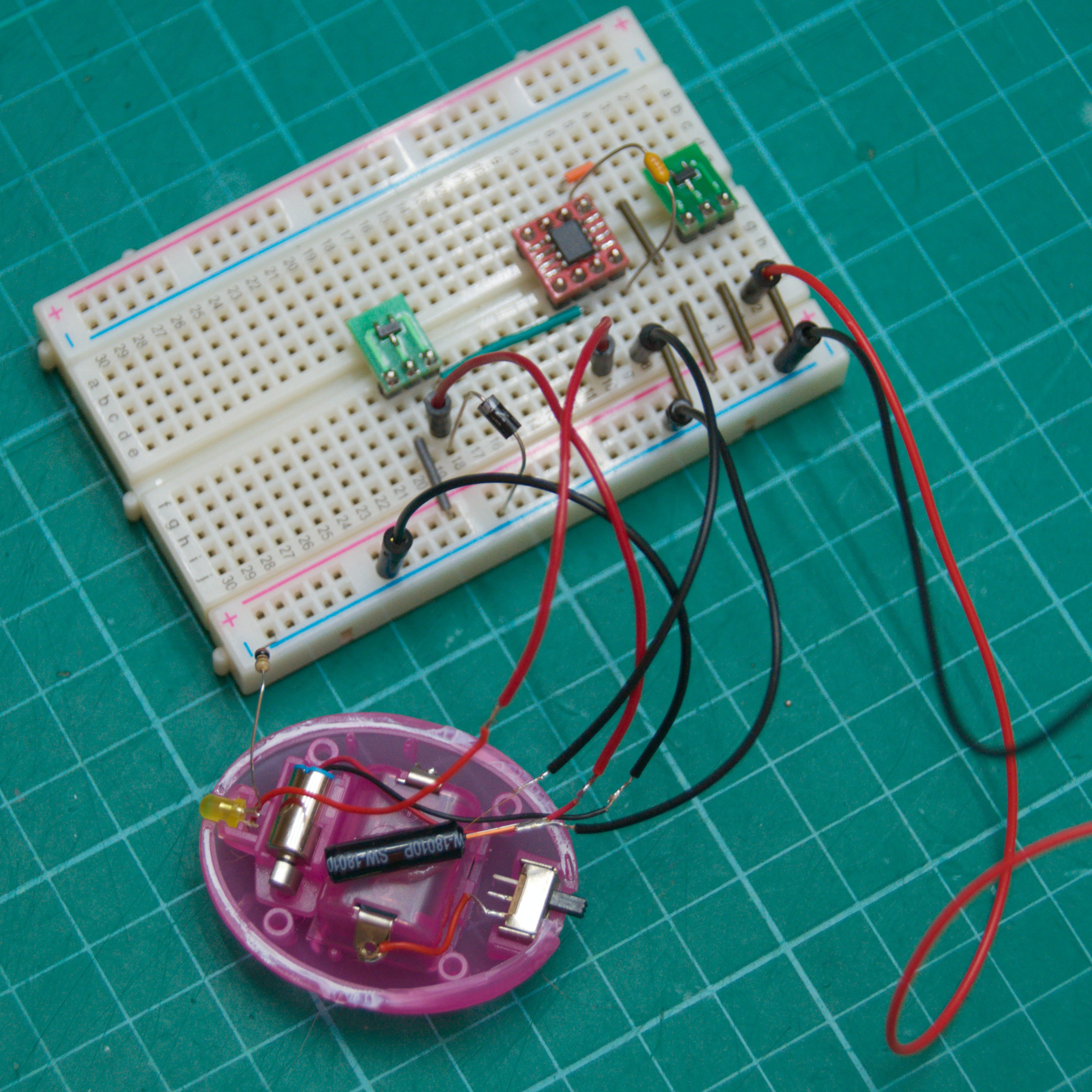
I prototyped the proposed schematic on a breadboad for testing.
This way I was able to test the code as I wrote it. The code is below with a few notes following explaining some parts of the code. It is fully commented so that when in a few months if I have a project I want to use the PFS154-S08 for I can look back at this project as a refresher.
/* Smart SmartyKat Crazy Cruiser
 * Target Device: PFS154-S08
 *
 * Sam Perry 2023
 * github.com/sdp8483/Smart_SmartyKat_Crazy_Cruiser
 */

#include <stdint.h>
#include <pdk/device.h>
#include "auto_sysclock.h"

// Pin Defines - all pins are on port A
#define VIBE_PIN              0     /* vibration sensor input pin, used to wake from deep sleep */
#define MOTOR_PIN             4     /* motor control pin, controlled with a pmosfet */
#define LED_PIN               3     /* LED output pin, current source */

// Output Pin Fuction Defines
#define LED_ON()              PA |= (1 << LED_PIN)
#define LED_OFF()             PA &= ~(1 << LED_PIN)
#define LED_TOGGLE()          PA ^= (1 << LED_PIN)
#define MOTOR_ON()            PA &= ~(1 << MOTOR_PIN)
#define MOTOR_OFF()           PA |= (1 << MOTOR_PIN)


// Toggle the motor on and off to give toy some character using profiles
#define MAX_TICKS             64    /* go to sleep after this many ticks */
uint8_t tick = 0;                  /* tick count, number of T16 interrupts since starting T16 */
#define NUM_PROFILES          8     /* number of profiles, a new one is played each wake event to give more character */
uint64_t profile[NUM_PROFILES] = {0b1100110011001111111111000000000010101010101010101010111111111111,
                                  0b1111111111111111111111111111111111111111111111111111111111111111,
                                  0b1100110011001100110011001100110011111111111111111111111111111111,
                                  0b1111111111001111001111001111001111001111001111001111001111001111,
                                  0b0101010101010101010101010101010101010101010101010101010101010101,
                                  0b1111001110011100111001110011100111001110011100111001110011100111,
                                  0b1110111000000111000000000000000011111111111111111111111111111111,
                                  0b1110101010101010000000001111111101010101000000001111111101010101};
                                   /* motor will be turned on when bit is 1 and off when bit is 0
                                       this playback profile is backwards */
uint8_t profile_i = 0;              /* profile number to playback, increments each wake */

// State Machine
typedef enum {
  GOTO_SLEEP,                       /* prepare to sleep */
  SLEEP,                            /* toy is in deep sleep */
  WAKEUP,                           /* toy was awaken from deep sleep */
  TOCK,                             /* T16 calling for next profile point */
  LIGHT_SLEEP,                      /* light sleep between ticks */
} fsm_states_t;

volatile fsm_states_t fsm_state = GOTO_SLEEP;

// Function Prototypes
void settling_delay(void);          /* use timer3 as delay to wait for vibe sensor to settle */

// Service Interrupt Requests
void interrupt(void) __interrupt(0) {
  /* Some notes and thoughts about interrupts on the PFS154
   *  Section 5.7 of the datasheet contains information about the interrupt controller.
   *  When an interrupt is triggered global interrupts are disabled, ie __disgint() is automaticaly called.
   *  CPU steps into ISR function below and executes code there. When done __engint() is automaticaly called and
   *  code execution starts in the main loop where it left off. Confusingly the datasheet says that even if INTEN = 0
   *  INTRQ can still be triggered by the interrupt source. So the peripheral or port should be further disabled to prevent
   *  triggering. */

  if (INTRQ & INTRQ_PA0) {          /* wake pin was pulled low */
    INTRQ &= ~INTRQ_PA0;            /* mark PA0 interrupt request serviced */
    fsm_state = WAKEUP;             /* change state */
  }

  if (INTRQ & INTRQ_T16) {          /* timer has expired */
    INTRQ &= ~INTRQ_T16;            /* mark T16 interrupt request serviced */
    T16C = 0;                       /* reset timer to zero */
    fsm_state = TOCK;               /* get next profile point */
  }

  if (INTRQ & INTRQ_TM2) {          /* LED toggle timer */
    INTRQ &= ~INTRQ_TM2;            /* mark interrupt request serviced */
    fsm_state = LIGHT_SLEEP;        /* go to light sleep */
  }

  if (INTRQ & INTRQ_TM3) {          /* settling delay has expired */
    INTRQ &= ~INTRQ_TM3;            /* mark interrupt request serviced */
  }
}

// Main program
void main() {
  MISC |= MISC_FAST_WAKEUP_ENABLE;  /* enable faster wakeup, 45 ILRC clocks instead of 3000 */

  // Initialize hardware
  PADIER = 0;                       /* on reset all pins are set as wake pins, setting register to 0 to disable */
  PBDIER = 0;                       /* there is no port B on the -S08 but without setting this to 0 the uC will wake unexpectedly */

  // Set Vibration Sensor pin as input
  PAC &= ~(1 << VIBE_PIN);          /* set as input (all pins are input by default, setting to make sure) */
  PAPH |= (1 << VIBE_PIN);          /* enable pullup resistor on pin */

  // Set output pins
  PAC |= (1 << MOTOR_PIN);          /* set motor control pin as output */
  PAC |= (1 << LED_PIN);            /* set led pin as output */
  LED_OFF();                        /* set initial LED state */
  MOTOR_OFF();                      /* set initial motor state */

  // Forever Loop
  while (1) {
    switch (fsm_state) {
      case GOTO_SLEEP:
        __disgint();                /* disable global interrupts */

        T16M = T16M_CLK_DISABLE;    /* turn off tick timer */
        TM2C = TM2C_CLK_DISABLE;    /* stop LED toggling */
        LED_OFF();
        MOTOR_OFF();

        settling_delay();           /* delay for vibe switch to settle */

        INTEN = 0;                  /* disable all interrupts */
        PADIER = (1 << VIBE_PIN);   /* enable only one wakeup pin */
        PBDIER = 0;                 /* make sure port B does not wake */
        INTEGS |= INTEGS_PA0_FALLING;
                                    /* trigger when switch closes and pulls pin to ground */
        INTEN |= INTEN_PA0;         /* enable interrupt on wake pin */
        INTRQ = 0;                  /* reset interrupts */

        fsm_state = SLEEP;          /* change state */
        break;

      case SLEEP:
        __engint();                 /* enable global interrupts */
        __stopsys();                /* go to deep sleep */
        break;

      case WAKEUP:
        __disgint();                /* disable global interrupts */
        INTEN = 0;                  /* disable all interrupts */
        PADIER = 0;                 /* disable wakeup pin */
        PBDIER = 0;                 /* disable port B wake pins to be sure */

        T16M = (uint8_t)(T16M_CLK_ILRC | T16M_CLK_DIV1 | T16M_INTSRC_13BIT);
                                    /* use 55kHz clock divided by 1, trigger when bit N goes from 0 to 1
                                     * T16 is used as the tick count to determins playback of profile for motor */
        T16C = 0;                   /* set timer count to 0 */
        INTEN |= INTEN_T16;         /* enable T16 interrupt */
        INTRQ = 0;                  /* reset interrupts */

        // use timer2 to toggle LED
        TM2C = (uint8_t)(TM2C_CLK_ILRC | TM2C_OUT_PA3 | TM2C_MODE_PERIOD);
        TM2S = (uint8_t)(TM2S_PRESCALE_DIV4 | TM2S_SCALE_DIV3);
        TM2B = 250;                 /* set timer frequency to 6.8Hz */
        INTEN |= INTEN_TM2;         /* enable timer2 interrupt */

        tick = 0;                   /* reset tick count to reset profile playback */
        fsm_state = TOCK;           /* change state to set motor playback from profile */
        break;

      case TOCK:
        __disgint();                /* dont interrupt during tock */
        if (tick >= MAX_TICKS) {    /* done playing? time for sleep */
          profile_i++;              /* play next profile on wake */
          profile_i = (profile_i > (NUM_PROFILES - 1)) ? 0 : profile_i;
                                    /* constrain profile_i */
          fsm_state = GOTO_SLEEP;   /* change state, go to sleep */
          break;                    /* don't execute remainder of code */
        }

        // get motor state in profile playback based on tick number
        if (((profile[profile_i] >> tick) & 0b01) == 1) {
          MOTOR_ON();
        } else {
          MOTOR_OFF();
        }

        tick++;                     /* increment tick */

        __engint();                 /* enable global interrupts */
        __stopexe();                /* light sleep, ILRC remains on */
        break;

      case LIGHT_SLEEP:
        __engint();                 /* enable global interrupts */
        __stopexe();                /* light sleep, ILRC remains on */
        break;

      default:
        fsm_state = GOTO_SLEEP;     /* something is wrong, go to sleep */
        break;
    }
  }
}
// Use timer3 to delay while vibration sensor settles
void settling_delay(void) {
  TM3C = (uint8_t)(TM3C_CLK_ILRC | TM3C_OUT_DISABLE | TM3C_MODE_PERIOD);
  TM3S = (uint8_t)(TM3S_PWM_RES_8BIT | TM3S_PRESCALE_DIV4 | TM3S_SCALE_DIV13);
                              /* setup for 0.256sec period */
  TM3B = 250;                 /* timer3 counts up to this value before interrupting */
  INTEN |= INTEN_TM3;         /* enable interrupt for timer3 */
  __engint();                 /* enable global interrupts */
  LED_ON();                   /* to see that delay is happening */
  __stopexe();                /* light sleep for a delay */
  LED_OFF();                  /* delay is done */

  __disgint();                /* disable global interrupts */
  TM3C = TM3C_CLK_DISABLE;    /* disable timer */
}

// Startup code - Setup/calibrate system clock
unsigned char _sdcc_external_startup(void) {
  /* Set the system clock
   * note it is necessary to enable IHRC clock while updating clock settings or CPU will hang  */
  PDK_USE_ILRC_SYSCLOCK();          /* use ILRC 55kHz clock as sysclock */
  PDK_DISABLE_IHRC();               /* disable IHRC to save power */
  EASY_PDK_CALIBRATE_ILRC(F_CPU, TARGET_VDD_MV);

  return 0;   // Return 0 to inform SDCC to continue with normal initialization.
}
Here are some of the highlights of the code and why I went in the direction I did.
- The main code loop contains a state machine. This was the simplest way for me to organize the code and to have the toy go though a few different modes.
- During play time the code is executed using Timer16 to generate an interrupting clock that I call tick.
- The motor is controlled using on/off commands. I thought using PWM to control the motor was more complicated then needed. Instead the profile variable stores a 64bit variable that is shifted through bit by bit to set the motor state for each Timer16 interrupt. When the code is finished shifting through this variable then the toy goes to sleep.
- The profile variable is an array so that the toy does not behave the same way each time it wakes. This gives it some character and hopefully makes it more fun.
- The LED is blinked using Timer2. I was toggling it using the TOCK state but that meant that the toggle rate was linked to the tick rate. I wanted the LED to toggle faster then I wanted tick to run. I found that Timer2 regardless of if the INTEN bit for it was set would call the interrupt function and mess with how long it took the toy to shift through the profile. To solve this when Timer2 interrupts it sets the state the LIGHT_SLEEP. This way the TOCK state is only called after an interrupt from Timer16.
- I used Timer3 as a settling delay. I thought that if the vibration switch was still wiggling while the toy was getting ready to sleep then the toy would never sleep. This way there is a ~256ms delay to let the motor spin down and the vibration switch to settle down.
That is it for the code. I have achieved my goal so far with the modification. The toy is easy to wake up with a slight tap and then remains active for about 10 seconds. If the toy is still being played with it continues running for longer but otherwise it goes into deep sleep to save battery power. In deep sleep I measured a current consumption of 0.3uA at 3.0V. During play with the same voltage I measured a maximum of 40mA.
Now for the final part of this project, get everything back in the housing and button it up. It looks like it will be tight so I may have to cut away some of the internal supports to make room.
Discussions
Become a Hackaday.io Member
Create an account to leave a comment. Already have an account? Log In.