JP Gleyzes
-
kokot version 3 (hall effect switch)
06/16/2023 at 09:08 • 0 commentsThe IR sensor was from time to time blinded by sun...
I simply replaced it by a hall effect switch.
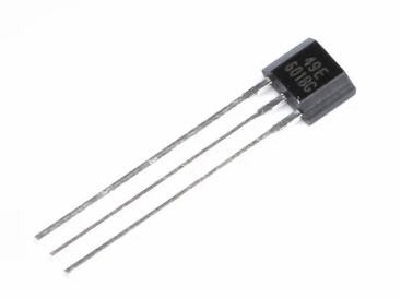
I choosed a 3.3V chip with the reference SS49E
![]()
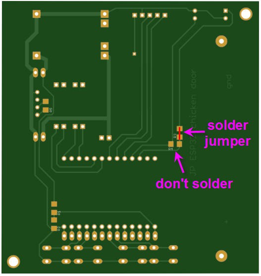
To connect it to the PCB and replace the IR sensor, follow these guidelines
- short R3 with a copper wire
- unsolder R4
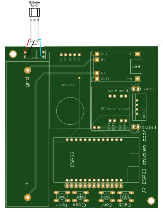
- connect the sensor as follows
![]()
![]()
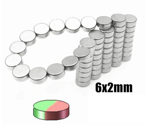
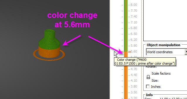
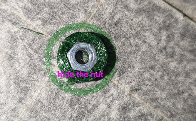
Then replace the 3D printed "wheel" by the magnet holder. You will need to glue a "diametrical magnet 6mm diameter, 2mm width"
![]()
Note that the 4mm nut is hidden into the printed part (add a filament change on top of the nut)
![]()
![]()
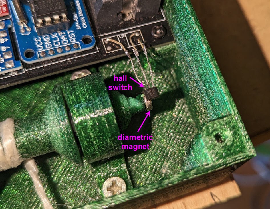
When finished the hall sensor should fly 2 to 3mm above the magnet
![]()
The code of the project remains strictly the same and is still available on my github page
-
Kokot Android App
03/16/2023 at 12:06 • 0 commentsAs the ESP32 has embeded Bluetooth Low Energy, I have coded a simple Android Application.
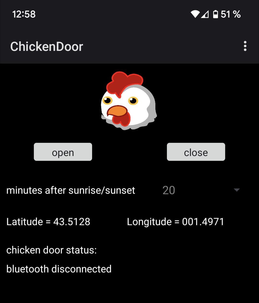
In fact it is very very basic !
![]()
With it you simply can:
- setup your latitude/longitude (needed for a correct computation of sunrise and sunset hours)
- setup the margin to open/close your door after sunrise/sunset
- open or close the door manually (same behavior as the physical buttons/touchpads on the board)
- log board status
I must admit that there is a caveat with this app... it only works when the ESP32 is not sleeping and when your are in close range to the board (10 to 20m max).
But it does the job !
Source code and .apk files are available on my github kokot project here
-
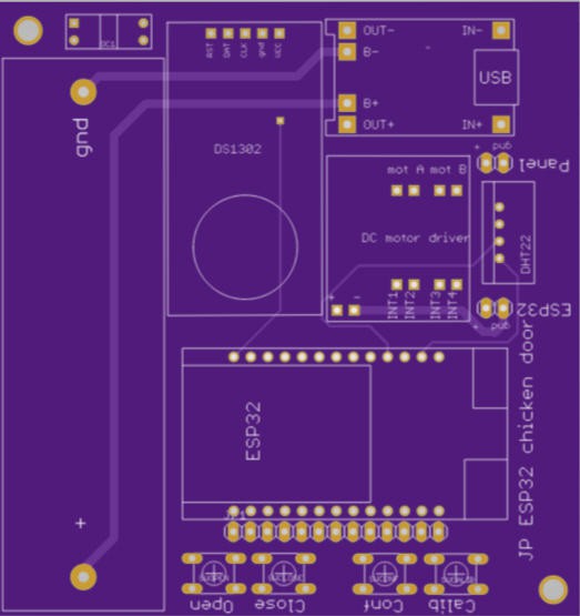
Kokot PCB version2
02/13/2023 at 14:51 • 0 commentsPCBWay is a Chineese PCB manufacturer. PCBWay has specialized in PCB prototype, small and medium batch production. It was founded in 2014, and are constantly growing. With over 15 years’ professional experiences and advanced manufacturing capabilities of their factories, in the past 4 years, their products have been well marketed in 150 countries and used by 250,000 clients around the world.
PCBWay contacted me end of january and proposed to sponsor my project.
I indeed rerouted my PCB to have a much nicer double sided design. Then I ordered a batch production. Ordering was very simple: just drop your gerber files into their Quick Order page.
Then use the online Gerber viewer to check your pcb.
![]()
When satisfied click on the order button and a few days later you get the awaited parcel. Shipment was incredibly fast, parcel arrived at home (France) less than 6 days after ordering!
Here is the video for the unboxing:
-
Open/close calibration : the "rotary encoder"
02/07/2023 at 16:30 • 0 commentsThe very classical way to determine "opened" and "closed" postions of the door is to add "home switches" to the door.
One would be at the bottom and the second at the top of the door.
Well I started with this solution and soon discovered that the chicken are not "clean" birds so that the floor of the coop is often full of "straw" (not to say shit !)
Placing home switches into the coop was not a very good idea.
Instead adding a "rotary encoder" to the shaft has a lot of advantages :
- no flying wires
- no electronic part with contacts which could rust of oxydize
- good precision
- possibility of detecting blockages of the door
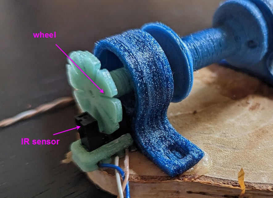
I thus made a simple wheel with 8 slots. The wheel rotates in front of an IR sensor and sends "pulses" to the ESP32 inside an interrupt routine
![]()
This routine is quite tricky as it has to take into account signal "bouncing" when the slot goes from dark to light...
But the software implementation is finally very very simple !
void IRAM_ATTR optical_ISR()    //IR sensor interrupt routine
{
  if ((millis() - IRtimeout) > 250)
  {
    IRtimeout = millis();
    if (chickenStatus == opening) tops++;
    else tops--;
    //Serial.println( tops);
  }
}
A simple timeout is added into the interrupt... if the signal bounces faster than 250ms, it will be considered as noise, and only the first pulse will be counted.
Remember that we expect a motor turning at 10 rotations per minute. That is 8*10 = 80 calls of the interrupt every minute... Plenty of time to debounce the switch.
Note as well that the Serial.println(tops); is commented.... If not it may occur that the interupt wll be called a second time whie printing is not finished... and this will crash the ESP32 (guru panic!). DO NOT uncomment this line if you want a safe behavior.
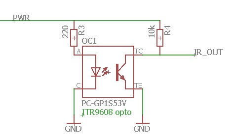
Finally here is the schematics of this sensor
![]()
You will note that the IR Led and the phototransistor are not powered directly by the battery, but instead they are powered via a PWR pin of the ESP32. Doing this allows to switch the IR sensor off when the ESP32 is in deepsleep mode. Simply configure PWR pin as "input" and that's it, you save 20mA of the led!
Ok we have now a way to "count the pulses" when the door opens or closes, but we do not know the absolute posiiton of this door... We have to add a "calibration procedure".
Calibration of the door
This calibration will require the help of the user... It must be done once when the door is installed.
- Start with the door in closed position
- touch or press the "Calib" button (do not release it)
- reset the ESP32 (reset button on the lolin lite module)
- the door will start to open
- when in the desired "open position" release the calibration button
That's it the door is calibrated!
You can of course re calibrate the door any time you want, although it shouldn't be necessary as the calibration is stored into the eeprom of the ESP32 and wouldn't erase even after a power disconnection.
-
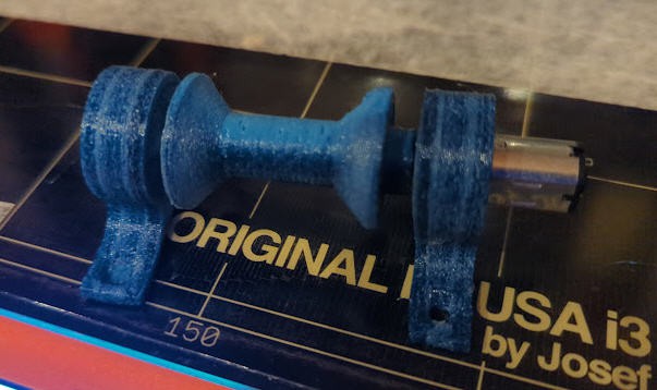
Qualifying the DC motor
02/06/2023 at 13:12 • 0 commentsTo qualify the motor I designed a 3D printed motor mount.
![]()
It's composed of a rotating pulley and two motor+shaft holders. With it, it was easy to fix a rope and to try to pull "things".
The conclusion are:
- the motor can pull up to 300g with this pulley before stalling
- a safe weight should be between 200 and 250g
- the motor draws 40mA as specified and at full load and up to 60mA when stalling
- operation is safe when powered at 4V instead as 3V (specs). So a fully charged Li-ion battery can be used.
Kokot: a low energy chicken coop door
This automatic chicken coop door will help to keep your chickens safe