Close
0%
0%

Simon game with ATtiny13

Full-featured clone of a famous “Simon” game for training your visual and acoustic memory. Electronic kit simple enough for beginners.

Similar projects worth following
This project page is about an electronic set developed for ÚDiF alias Amazing Theatre of Physics.
The aim of this project is to create a simple but still playable toy which can be used to learn basic skills in electronics.

The heart of the game is ATtiny13. It is low power AVR 8-bit microcontroller with 1 kB flash memory, 64 bytes EEPROM and 64 bytes SRAM.

It has six I/O pins, from which one acts as a reset and is used to start a new game, four are connected to LEDs and buttons and the last one leads to the magnetodynamic buzzer. The device is powered from CR2032 lithium cell.

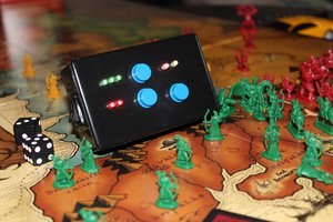
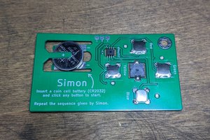
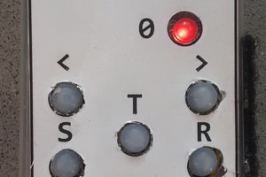
As mentioned, the device contains four LEDs of different colors (red, orange, yellow and green) connected with four button switches. (Blue or 525 nm green LEDs can't be used because they have too high forward voltage and wouldn't work well with partially discharged battery.)

After pressing each of those buttons, the LED lights up and information about the button state can be read by a microcontroller. The pins of a microcontroller are bi-directional, so they can be changed from input to output in any time and can control LEDs instead of the buttons (see simplified diagram).

To avoid to making short-circuit on output pins, changing between input and output can be done only in low state (disabled internal pull-up resistor). Because each LED has different efficiency, resistors of different values must be connected in series with them.

The high-impedance (42 ohm) buzzer is connected in series with a capacitor (to eliminate DC voltage) to the output of internal 8-bit timer/counter. Like in an original game, each color is producing a particular tone when it is pressed or activated by the microcontroller and the frequencies are in an exact ratio 3:4:5:6 (50% duty cycle).

Sufficient pseudo-random sequences are generated by a linear congruential generator defined by the recurrence relation:

x[i+1] = (2053 * x[i] + 13849) mod 216

Eight bit pairs of 16-bit number x[i] are XORed together to produce a number 0 to 3. Quality of this generator can be checked displaying the whole 65536 elements long sequence (it is good enough for this purpose).

The value of random seed x[0] is generated from combination of non-connected input of A/D converter and jitter between watchdog timer and calibrated RC oscillator. So the probability of repeating the same sequence is very low.

The watchdog timer is used also for buttons debouncing and for auto power-off after a minute of inactivity. In power-down mode (also after the game is over) the consumption is approximately 0.15 microamps.

Best score is saved to the EEPROM (including the seed), so it is possible to re-play the best game (even after removing the battery).

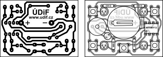
The concept of this electronic set is to make it easy to build without any special tools or skills. The single-sided printed circuit board is optimized to be easily drawn by hand with a permanent marker and etched in a solution of ferric chloride (tested at summer camps and hobby groups for children).
The game can run in five modes:

  • When the game is started only using the middle (reset) button, random seed is generated and you have to memorize and repeat increasing sequence of colors and tones. In higher levels the game goes faster. If you make a mistake, the correct LED blinks three times and game-over animation is played. If you have beaten the best score, your game (achieved level and seed value) is saved to the EEPROM and best-score animation is played.
  • If you hold orange button during reset, you can continue with the best-scored game. It starts on the highest achieved level.
  • When you hold yellow button during reset, you can play the best-scored game from the beginning.
  • If the red button is pressed during reset, the best score is erased and you start a new random game as in the first case.
  • Pressing the green button during reset starts playing the pseudo-random sequence (starting by a random seed). It takes almost 3.5 hours before the sequence starts repeating.

Creative Commons LicenseThis project with exception of the software is licensed under a Creative Commons Attribution-NonCommercial 4.0 International License. The software (source and binary) is licensed under the MIT License.

Simon_attiny13.ino

Software source code (tested in Arduino IDE with MicroCore board definition, but no Arduino-specific libraries are used). GCC flags: "-Os". Licensed under the MIT License.

x-arduino - 6.08 kB - 12/13/2016 at 23:42

Download

Simon_attiny13.hex

Compiled binary code (Intel HEX format). Fuse bits should be kept in default values (lfuse: 0x6a, hfuse: 0xff). Licensed under the MIT License.

hex - 2.84 kB - 12/13/2016 at 23:42

Download

Simon_attiny13_lfsr.ino

Software source code (Linear-feedback shift register used instead of Linear congruential generator). GCC flags: "-Os". Licensed under the MIT License.

x-arduino - 6.49 kB - 01/01/2017 at 19:02

Download

Simon_attiny13_lfsr.hex

Compiled binary code (Intel HEX format, Linear-feedback shift register used instead of Linear congruential generator). Licensed under the MIT License.

hex - 2.77 kB - 01/01/2017 at 19:02

Download

simon_attiny13_en.zip

Manuals, schematic, PCB and components placement. Creative Commons Attribution-NonCommercial 4.0 International License. English language.

Zip Archive - 603.18 kB - 12/14/2016 at 14:43

Download

View all 7 files

  • 1 × ATtiny13A-PU or ATtiny13V-10PU
  • 5 × Button switch 6×6×9 mm should be higher than LEDs
  • 1 × 42 ohm buzzer small passive electrodynamic speaker
  • 1 × Electrolytic capacitor 100 μF 5×7 mm
  • 1 × 5mm red diffuse LED

View all 14 components

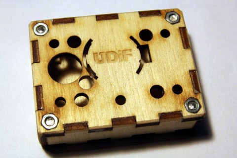
  • Laser-cut plywood box

    Vojtak02/19/2017 at 00:38 0 comments

    The box for Simon game is designed to be laser cut from 3.2 mm thick plywood.

    • Red line marks laser cuts.
    • Green areas should be engraved to the depth of approx. 0.5 mm.
    • Cyan areas should be engraved to the depth of approx. 1.4 mm.
    • Blue areas should be engraved to the depth of 2.3 mm (M3 nut height).

    Bottom wall is removable and fixed by four M3 × 16 mm countersink screws.

    The M3 nuts are set in the top wall which is glued to four side walls.

    Four small L-shaped parts should be glued to the inner corners of the box (to reinforce the plywood under the nuts).

    Small cross-shaped parts should be glued to the bottom wall under four button switches.

    Files for laser cutter are in the download section.

  • Linear-feedback shift register instead of Linear congruential generator

    Vojtak01/01/2017 at 19:32 0 comments

    In a discussion below the project review [RÖB] asked if a linear congruential generator is better that a linear feedback shift register or how are they different.

    So I have tried an example for the 16-bit maximal-period Galois LFSR from Wikipedia. The result is really not bad as you can see in the pictured data (only a subtle vertical pattern can be noticed):

    The Wikipedia example was slightly modified to work with seed = 0 (period of this LFSR is only 65535):

    uint8_t simple_random4() { // using LFSR instead of LCG
      for (uint8_t i = 0; i < 2; i++) { // we need two random bits
        uint8_t lsb = ctx & 1; // Get LSB (i.e., the output bit)
        ctx >>= 1; // Shift register
        if (lsb || !ctx) { // output bit is 1 or ctx = 0
          ctx ^= 0xB400; // apply toggle mask
        }
      }
      return ctx & 0b00000011; // remainder after division by 4
    }
    

    Because ATtiny13 can't use MUL instruction but linear congruential generator uses a multiplication, the linear-feedback shift register is more effective and uses 22 bytes less space in flash memory (modified source and HEX file are in the download section). So maybe I can add some additional feature in the future.

  • Development process

    Vojtak12/14/2016 at 00:24 0 comments

    The project of Simon game was developed as an electronic set for ÚDiF alias Amazing Theatre of Physics.
    The aim was to create a simple toy to teach basic skills in electronics.

    The first version (summer 2015) was driven by ATtiny45 or ATtiny85 microcontroller, which has 4 or 8 times more flash memory than ATtiny13. It used many not-so-much effective Arduino libraries.

    During winter 2015/2016 I developed a simplified version to fit into a cheaper microcontroller. But it wasn't able to store best score into EEPROM.

    In autumn 2016 I decided to rewrite and optimize the program and squeeze almost all functions into 1 kB of ATtiny13 microcontroller. I made some improvements in pseudo-random generator and made minor changes in combo-keys (for re-starting best-scored game and deleting memory). I also added a demo function (infinite pseudo-random loop).

View all 3 project logs

Enjoy this project?

Share

Discussions

Fausto wrote 10/09/2022 at 02:00 point

Hello!!! Query: Has anyone successfully tried to port the code to work correctly on the ATtiny85? I'm new to this, and it's been difficult for me to get it, and I don't have an ATtiny13 unfortunately. Thank you

  Are you sure? yes | no

markus_rohner1 wrote 07/07/2022 at 09:51 point

Hi, Quesion: How does the ATtiny wake up after it is in sleep mode? There are no interrupts set and still when pressing the reset key, the game starts. I just do not know why

  Are you sure? yes | no

Vojtak wrote 07/07/2022 at 09:57 point

It just does the default function of the reset pin: resets the microcontroller and the new game starts.

  Are you sure? yes | no

odradek wrote 11/11/2020 at 11:48 point

Hi Vojtak,

Thaks you by this fantastic project!!!, We use your code as base to solder and hacking skills. Take a view: https://github.com/0dr4d3k/simon_attiny13

First, we simplify your code to less than 700 bytes and then we add some addons as player vs player mode and a happy Easer Egg as Jazz Machine genereator.

Thanks again by your work.

  Are you sure? yes | no

Amaro Vero wrote 12/21/2019 at 17:09 point

First of all I want to thank you! We built some of these as a school project and it was a success!

We've made schematic and layout with Multisim and Ultiboard and etched some boards.

I've got a question: why is lvl inverted when written in the EEPROM?

  Are you sure? yes | no

Vojtak wrote 12/21/2019 at 17:44 point

Hi.

Data in EEPROM are stored inverted because the default values are 0xFF and I wanted these values to be interpreted as zeroes on the first use.

  Are you sure? yes | no

dzexperience1 wrote 11/06/2019 at 22:36 point

help i have this error

Sketch uses 1040 bytes (101%) of program storage space. Maximum is 1024 bytes.

Global variables use 19 bytes (29%) of dynamic memory, leaving 45 bytes for local variables. Maximum is 64 bytes.
Sketch too big; see http://www.arduino.cc/en/Guide/Troubleshooting#size for tips on reducing it.
Error compiling for board ATtiny13.

  Are you sure? yes | no

Amaro Vero wrote 09/23/2019 at 15:49 point

What kind of buzzer is used in this project? I usually see piezo buzzers driven by MCUs but I feel like it's not the case here... maybe an electromagnetic one? Is so what's the rationale behind that choice?

  Are you sure? yes | no

Vojtak wrote 09/25/2019 at 10:10 point

The main reason is the price. The 42 ohm electromagnetic buzzer can be found for $0.80 for 10 pcs on AliExpress.

  Are you sure? yes | no

Amaro Vero wrote 09/25/2019 at 15:59 point

Got it. It also sounds much better than the piezo! I'm trying different buzzer-capacitor combos. The one I've got (15 ohms) seems to work now with a 22uF cap (100uF doesn't) but I also got a weird behaviour a few times where the LED sequence would speed up with the buzzer connected. Definitely harder to drive.

  Are you sure? yes | no

Amaro Vero wrote 09/26/2019 at 15:55 point

I'm trying to learn more on how to drive a magnetic buzzer/sounder. Most datasheets recommend using a flyback diode and driving the buzzer with a transistor. Where did you get the idea of using a series capacitor?

  Are you sure? yes | no

Chris wrote 07/21/2019 at 12:24 point

Does anyone here know that the pcb layout is backwards? Need a mirror image in order to make it work on the bottom layer as in the picture.

  Are you sure? yes | no

Shreyas Achrekar wrote 08/08/2019 at 12:54 point

Yes...even i was confused...i have Mirrored the layout😄👍🏻

  Are you sure? yes | no

Chris wrote 08/18/2019 at 16:14 point

yes I figured it out, Just can't compile the code for attiny13.

getting msg:

"Sketch too big; see http://www.arduino.cc/en/Guide/Troubleshooting#size for tips on reducing it.

Error compiling for board ATtiny13."

  Are you sure? yes | no

erwin.meyvaert wrote 01/11/2018 at 17:32 point

I have made de simon game but i have a error WDTIE was not decleared in this scope

How can i fixed please

I use a ATtiny85

Kind regards

  Are you sure? yes | no

Vojtak wrote 01/11/2018 at 21:18 point

Hi.

ATtiny85 uses different register names. Some changes in the source code would be necessary, according to the datasheet.

  Are you sure? yes | no

Aledaniel1 wrote 04/22/2018 at 22:32 point

Erwin, I got the same error, to fix it, You have to make the following change: 

WDTCR = ( 1 << WTIE);   to WDTCR = ( 1 << WDCE); 

  Are you sure? yes | no

Patryk wrote 05/12/2017 at 08:30 point

Hello, I was about to try this myself. After opening .ino file in Arduino IDE,  I get this error: https://pastebin.com/uuhF2UWE
Just clicked Compile to check for errors, didn't set board or anything yet. Could you help me? :)

  Are you sure? yes | no

Vojtak wrote 01/11/2018 at 21:33 point

Hi. You have to add MicroCore to the Board Manager and use ATtiny13 (B.O.D.: "Disabled", Clock: "1.2 MHz", GCC Flags: "-Os"). This won't work on Arduino Nano since it doesn't use Arduino universal libraries (they are too large and ineffective for tiny microcontrollers like ATtiny13).

  Are you sure? yes | no

Amaro Vero wrote 09/25/2019 at 09:05 point

I flashed the Microcore bootloader (1.0.4 from https://github.com/MCUdude/MicroCore) on an ATtiny13-20PU and I can blink a LED using an Arduino board as a programmer and the Arduino IDE. I've tried compiling Simon_attiny13.ino with the settings above:

board: ATtiny13

BOD disabled

LTO enabled

clock 1.2 internal

Programmer: Arduino as ISP

The GCC Flags option is not there anymore on Microcore 1.0.4 but inspecting 

C:\Program Files (x86)\Arduino\hardware\arduino\avr\platform.txt

I can see the -Os flag is set:

compiler.c.flags=-c -g -Os {compiler.warning_flags} -std=gnu11 -ffunction-sections -fdata-sections -MMD -flto -fno-fat-lto-objects

Still the compiler fails complaining about the sketch being too big:

Arduino: 1.8.10 (Windows 10), Board: "ATtiny13, 1.2 MHz internal osc., BOD disabled, LTO enabled (default)"

Sketch uses 1046 bytes (102%) of program storage space. Maximum is 1024 bytes.

Global variables use 19 bytes (29%) of dynamic memory, leaving 45 bytes for local variables. Maximum is 64 bytes.
Sketch too big; see http://www.arduino.cc/en/Guide/Troubleshooting#size for tips on reducing it.
Error compiling for board ATtiny13.

What's wrong?

  Are you sure? yes | no

Vojtak wrote 09/25/2019 at 10:22 point

The size of compiled binary depends on version of avr-gcc. I am not sure which version have I used to squeeze it into 1 kB, it was probably some kind of Arduino 1.6 for Ubuntu and MicroCore available those days. If you want to compile it by yourself, you can try LFSR version, it should be a little bit smaller. No bootloader is needed. Or you can just download the compiled binary (hex file) and burn it using avrdude.

  Are you sure? yes | no

Vojtak wrote 04/20/2017 at 22:41 point

If anybody wants to build their own Simon game, Makers in Little Lisbon are organising a soldering workshop: http://mill.pt/agenda/aprende-a-soldar-3/.

  Are you sure? yes | no

mc8454 wrote 01/02/2017 at 22:30 point

Nice. I made a really similar one using a 12F675 (or 12F629, don't remember) and PICBASIC, but I suppose the random generator was less sophisticated, and had no hi-score memory. 

Also, after first build, I found that larger LEDs (say 8-10 mm) could be easily placed over the push buttons (just bend the leads in the right way) so that they have a double function and lead to a polite finishing using just 4 holes on the case cover (ok, my version had no power button, just push one and the device woke up and start, after a long inactivity it went to sleep).

  Are you sure? yes | no

zakqwy wrote 12/20/2016 at 18:15 point

Great project, and the timing couldn't be better... I'm building a similar device as a Christmas present and am just starting firmware dev. Thanks for sharing!

  Are you sure? yes | no

danjovic wrote 12/14/2016 at 15:23 point

Awesome project! You have used a lot of clever tricks and designed a wonderful UI as well as a beautiful single sided board!

  Are you sure? yes | no

Vojtak wrote 12/14/2016 at 22:59 point

Thanks.

  Are you sure? yes | no

Similar Projects

Does this project spark your interest?

Become a member to follow this project and never miss any updates