Close
0%
0%

Tiny Bit Machine

An 8-bit solar powered gadget.

Similar projects worth following
Solar powered, battery free hardware to run an interpreter on the ATTiny85.

Currently have a working game written in 127 byte program.

Charge time in full sun: 3-6 minutes.
Run Time: 30-45 minutes.

Hardware to run (TGRK), a tiny handheld interpreter for the attiny85.

Program is stored in a 127 byte int8_t array.

Negative numbers (-128,-1) are keywords, positive numbers (0-127) are integers.

The device runs off a 1.5F, 5.5v supercapacitor which is charged by a small solar cell. To prevent the supercapacitor from exceeding its maximum of 5.5v, I have placed a 5.6v Zener diode to limit the voltage before the blocking diode and supercapacitor.

In direct sunlight it only charges up to ~5.2v, which is fine in my opinion. It can take 3-6 minutes to charge from 0v to 5.2v.

The device runs for about 30-45 minutes after a full charge. If the voltage goes below 2 volts, the device will go into deep sleep. When this happens the user will need to recharge it to keep working.

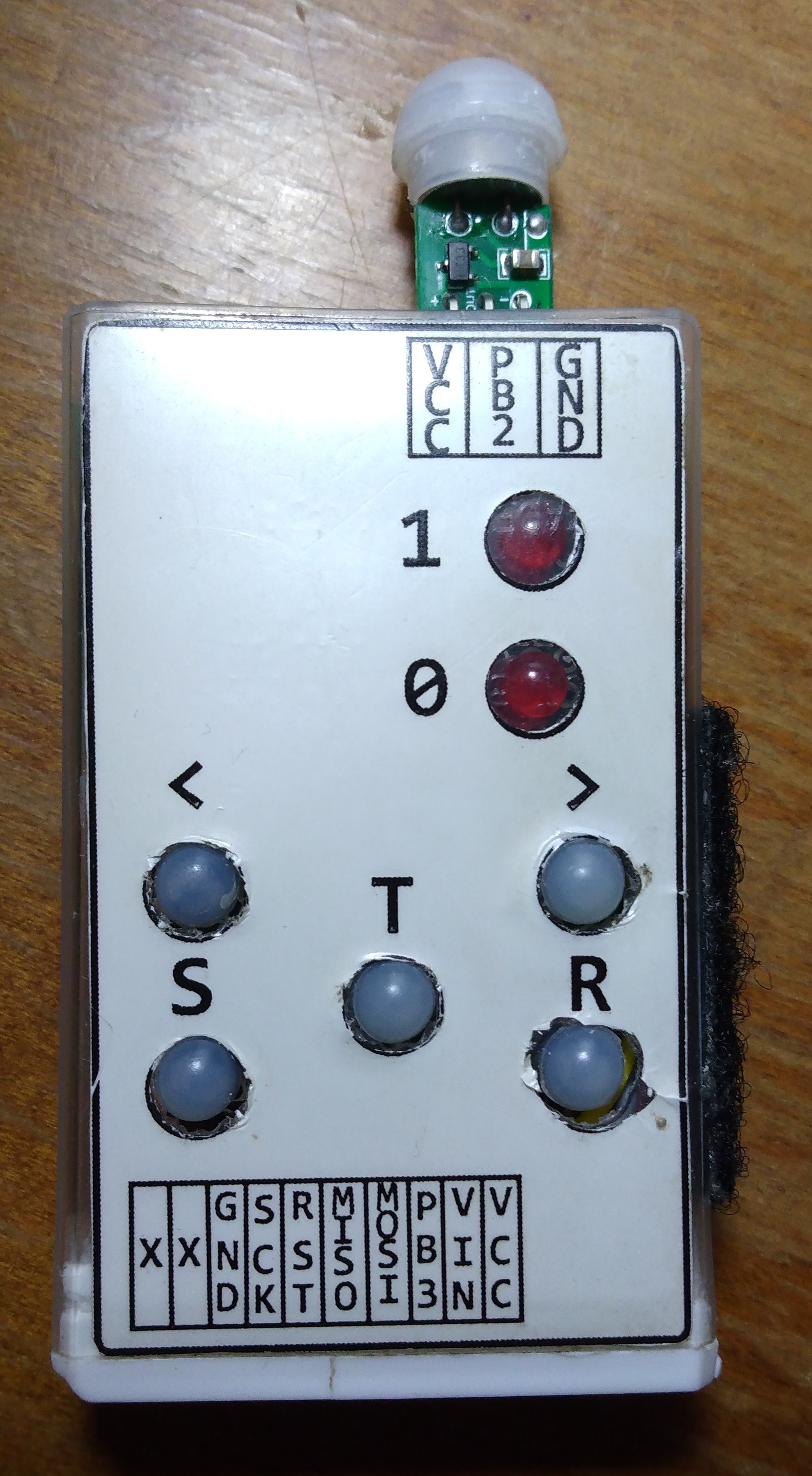
User input is 5 buttons on a resistor ladder on ADC2 of attiny85. Depending on what menu the user is in, they will do different things. With the exception the < and > buttons will always either be navigating menu, byte, or bit position.

  • Left Button       <
  • Right Button     >
  • Toggle Button  T
  • Save Button     S
  • Run Button       R

The devices output are two red LEDs. I chose red due to low forward voltage, and it is easier on the eyes if using the device in low light.

TGRK_KEYWORDS.pdf

Interpreter Keyword Table

Adobe Portable Document Format - 72.24 kB - 09/08/2024 at 23:59

Preview

TBM_TGRK.ino

Interpreter Arduino Sketch

ino - 31.32 kB - 09/08/2024 at 23:59

Download

tgrk.py

Python Serial Transfer Tool

x-python - 4.65 kB - 09/08/2024 at 23:59

Download

prog.grk

Program To Transfer Over Serial

grk - 901.00 bytes - 09/08/2024 at 23:59

Download

  • 1 × ATTINY85 Microprocessors, Microcontrollers, DSPs / ARM, RISC-Based Microcontrollers
  • 1 × 60x40 Proto Board For attaching components
  • 1 × Tic Tac Box Case
  • 1 × 8 Pin IC Socket
  • 1 × 53x30 5v Solar Cell

View all 14 components

  • A Fair Weather Friend

    g0730n09/27/2024 at 03:46 0 comments

    I work as a home repair contractor, and autumn becomes a very busy season for me as lots of people want to get things done before the rain begins. So I have not had any time to work on projects.

    I did discover on a very overcast day, the device will only charge to about 2.9 volts, maybe more if in light all day... but the panel used in this project is rated 5v, 30mA, in full direct sun, it really only provides 15-25 mA.

    On a very overcast day, current is only about 0.5 mA, and voltage much lower. Where I live we get about 6-8 months a year of such weather... It got me looking into energy harvesting IC's. But this project will not expand into that.

    The device can be fully charged in about 10-20 min if placed directly under a bright lamp indoors.

    I think all I will do on this project in the near future is assemble one of the PCB devices, and once all is tested release PCB files for that as well as update guide to reflect PCB assembly.

    I am thinking of a more advanced handheld device to port TGRK to, using either STM32, or ATMEGA328P instead of attiny85. As this device will have either an LCD character display or OLED screen, it will use a LiPo battery for energy storage instead of a supercap. But will still retain solar charging capability, in addition to usb charging. 

    This new device will have a 16-20 key keypad for programming on the device. As character variables will be a new feature, as well as on screen programming, instead of modifying bytes bit by bit, we can type in keywords as they appear in the keyword table, and the interpreter will convert the text representation to the integer keyword code. Because of this the interpreter will have to be modified, but I do intend to make TGRK programs somehow compatable between devices.

  • PCB's and New Game Update

    g0730n09/19/2024 at 18:06 0 comments

    The 5 PCB's I ordered came in. When I get the chance I will assemble one for testing.

    I am thinking of making a video of assembling the PCB device, we'll see.

    Somehow my "pet" survived through the night last night without making modifications to the game code. I was surprised and impressed! Making a day counter to see how many days it has survived is next on the plan for modifying the game code.

  • Virtual Pet Game

    g0730n09/18/2024 at 19:27 0 comments

    The "Virtual Pet" game I wrote about in the last log seems to be working fine. Although I was not able to keep it alive overnight.

    It seems like the voltage dropped below 2v during the night at some point, the power saving mode kicked in and the "pet" was not able to survive that.

    Currently when pet wakes up from its 8 minute naps, one LED (showing overall health level) is lit for about 20 seconds, which is the overall timeout for getting user input. I need to set this so if after the first button timeout, there is no user input, LED is off. 20 seconds on every 8 min is roughly 2 min on every hour. During an 8 hour night thats 16 min of wasted power. During the winter where i live we get up to 16 hours of darkness. Ideally the pet can survive through the night.

    Another idea is to have the pet "hibernate" if health (VCC voltage) drops below a certain level. Placing device in sun would be the only way to wake it in that case. While pet is in hibernation, no attention is needed from its owner. In this mode 16 hours has been tested for device not resetting and losing ram contents.

  • Multiple Interrupt Sources and Getting Button Input

    g0730n09/17/2024 at 18:49 0 comments

    I had an Idea to write a second game for the device, but in doing so I had to modify how the interpreter process button presses.

    Up until this point, when the keyword to wait for a button press was called "BG", the interpreter would wait indefinitely until a button was pressed. But in this new game, if there is no user input, I want the device to go into deep sleep.

    Also, because the buttons are on a resistor ladder, only the RUN button will wake the device up from deep sleep. I had to address the following issues and fix them:

    1. If no button is pressed when BG is called, after 5 seconds or set timeout, interpreter will continue. This allows the user to let the device go to sleep if there is no user input.
    2. When RUN button is pressed to wake interpreter from deep sleep (D0-D8), if it was not released fast enough, it would also kill the interpreter. As the RUN button is also the button used to exit the interpreter in normal operation. The fix was to set the "Button Pressed" flag to true immediately after waking, so the interpreter would not read another button press until the RUN button has been released and a new press is done.
    3. There was an issue with device not waking from button interrupt (PCINT3) or from WDT after one or two sleep cycles, it took me quite a while to fix the issue, and to this point I am not entirely sure what was causing the issues. It is confusing enough for me dealing with one interrupt source, but trying to deal with two simultaneously was conflicting. I think the issue was not disabling interrupts while clearing the PCINT3 flag. I will have to experiment with different types of interrupts more to understand them better. But now it is fixed. If we call (D8) in the interpreter, the device will go into low power mode for 8 minutes, or until the RUN button is pressed.

    The second game I have written is a "Virtual Pet" game. The concept is fairly simple.

    • When running program, if health is greater than 31 (25%), LED 1 will be lit, otherwise LED 0 will be lit. This allows the player to get a quick check on if there is immediate attention needed to the Pet.
    • "Feeding" Pet is done by placing device in sunlight. We can think of the animals hunger directly proportional to the voltage level of the super capacitor. If that drops below 2 volts and device goes into low power mode, we sure as hell better hope some of it's other stats are high enough or when we recharge the device it will wake up dead!
    • We can give the pet "water" by pressing the "<" button on device. Each press will add 10 points to it's water stat.
    • We can "Pet" the creature by pressing the ">" button, which adds 10 to it's "attention" stat. Watering the pet also adds 1 to this stat.
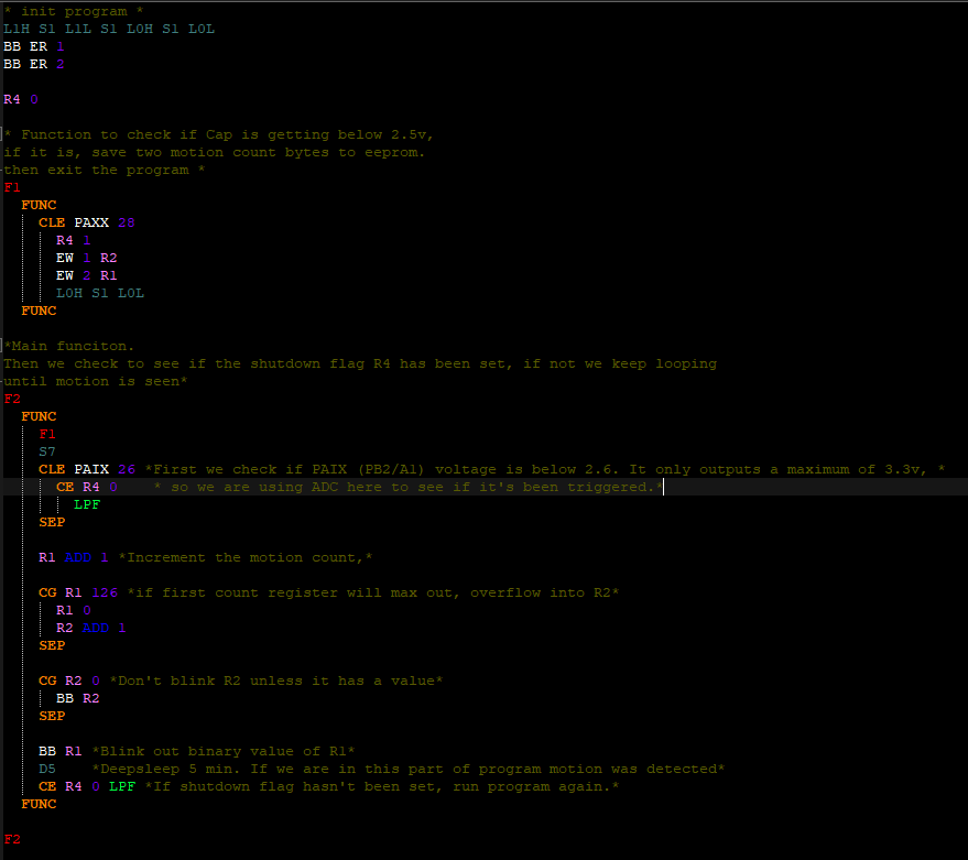
    • The pet's overall health and happiness can be viewed by pressing the "T" button, which will blink out a number between 1 and 127. This number is decided by the following formulas. Due to the order of operations TGRK calculates math, I had to write it in this format.
      * R2 is pets "hunger", determined by (VCC - 27) x 5*
      * 0 = starving [(27 - 27) x 5 = 0] *
      * 127 = full [(53 - 27) x 5 = 130 (rounds to 127) *
      R2 PAXX SUB 27 MUL 5
      
      * R7 and R8 Are temporary variables to store "Thirst" and "Attention" *
      * We divide all by 3, then add together to get a number between 0-127 *
      R7 R3 DIV 3
      R8 R4 DIV 3
      
      * R1 is pets overall health and happiness *
      * 0 = dead, 127 = Fat and Happy *
      R1 R2 DIV 3 ADD R7 ADD R8

     I haven't been able to test the game thoroughly due to the button processing and waking from sleep issues I have since fixed. I will load it up on device today and see how long I can keep this thing alive.

    With no input from user (Petting or Watering), every  40 or so minutes 8 thirst and 4 attention is subtracted from stats, every 8 minutes the device wakes up momentarily and increases a counter if no user attention is given. If the device is not in sunlight during this time, the hunger will increase as well.

    I need to modify game code so pet can also die if it's not...

    Read more »

  • More Game Balance Changes

    g0730n09/11/2024 at 23:33 0 comments

    I changed some things with the games balance.

    Firstly player starts with max HP (127), instead of 64.

    I also slightly amount monster does damage.

    There was a bug in the gold drop. If you look at the code you will probably spot it. Basically it was  adding our variables to player gold, then dividing. I fixed this by setting another registers variable to the formula result, then adding that to player gold register.

    With these new changes I have been able to get to level 108! Which is just 8 levels away from the end. 

    I Think at this point it is beatable but from about level 105-126 the player pretty much has to travel back to the inn after each fight to heal. Which becomes very tedious. Before these changes to game code after about level 55 player had to go back to heal after each fight. But that may have been mainly to the gold drops not being calculated correctly.

    I would like to add a fast travel to and from inn. Where each map being traveled will blink quickly so there would still be a sense of travel time but not having to click a button 100 times each way. To do this I need to shave off some bytes somewhere. I am not sure if its possible but will look it over again and see.

    There was also a bug in how the serial transfer tool was parsing comments, which I fixed. If the comments beginning and ending asterisk didn't have a space before and after it, strange things would happen. Now as long as the outside of comment asterisk is not touching a program keyword or value, it works as it should.

  • Game Difficulty

    g0730n09/11/2024 at 01:12 0 comments

    A turn based game that only has 2 input buttons is fairly easy, unless it is programmed in a way that it is unbeatable.

    The only skill required in this game is reading the binary number for HP, and deciding if its time to go back and heal.

    So far the highest level I have reached is level 85. At that point after each fight the player has to return to the inn to heal. If a monster only drops 10-20 gold, thats not enough health to survive another fight, much less two.

    The game is definitely playable at this point, but I am unsure if it's beatable. I need to really look at my game code and see if i can shave off a couple bytes somewhere and add some more complexity to the Player/Monster hit formulas, as well as the gold drop formulas.

    I suppose I could also give player 2 HP per gold spent, and each night at the inn costs player 64 gold.

    Anyhow, I am happy with where the project is for the end of contest, but I will be improving it when I get the time.

  • Gameplay Video

    g0730n09/10/2024 at 13:04 0 comments

    Gameplay video

  • Updates and Video

    g0730n09/09/2024 at 05:44 0 comments

    I had to really really slim the game code down, as well as change a few features in the interpreter code to accommodate some things for the game.

    Here is a somewhat long video demonstrating the game code and serial transfer program. I will try and make a video of playing through the game tomorrow.

    Here are the new changes, mainly the previously mentioned way of handling button input in the interpreter. There are always small changes I do but forget about to mention on here, but any changes to do with using keywords will be updated on the Keyword Table file.

    Using the keyword

    BG

     waits until a button press. When a button is pressed, it is stored in the "BV", and can be accessed like any other register:

    * Wait for button press *
    BG
    
    * Set value of R1 to button value (1-4) *
    R1 BV
    
    * Check if we pressed button 2 *
    CE BV 2


    Another thing I changed was accessing single byte EEPROM addresses. Before only 3 bytes at end of EEPROM were accessible using 6 different keywords, 3 for writing, and 3 for reading. I did this to reduce byte size in programs. But it felt too limited, so now there are only 2 keywords for accessing an EEPROM byte, and byes 382-502 are accessible to user to save data in, like this:

    * Write to EEPROM *
    EW (address) (value)
    EW 0 R1
    EW 1 12
    
    * Read from EEPROM *
    Rx ER (address)
    BB ER (address)
    R1 ER 0
    BB ER 117

     It now takes 3 bytes in program code to save to EEPROM, and 3 bytes to read.

    The address can be 0-117. 8 bytes at end of EEPROM are saved for a feature to be later implemented.
    This future feature will have one keyword for saving all 8 registers to last 8 bytes in EEPROM, and one keyword for loading those bytes back into the 8 registers. This could be good for saving a game, etc.

    The EEPROM keyword and address can not be used in a conditional like this:

    CG ER 32 12
    CE R3 ER 0

    This will result in an error. This is not a bug but a feature... For now.

    Now on to the new game code. I was able to pack a "fully" functional "RPG" game in 127 bytes. Think Pokémon on a one dimensional linear map with only 2 LED's to know what is going on in the game. This was quite the challenge, but I am glad I was able to program it in TGRK instead of adding it into the Arduino sketch.

    It ended up having a lot less features then originally planned, but I think with the right tweaks the difficulty can make it enjoyable to play. That is if you don't mind reading the binary codes blinked out to monitor your health level, and subtracting or adding to those blinks to know how many hit points you lost in the last battle, or how much gold you just spent on healing at the inn.

    Game Code

    R2 64
    
    F1
      FUNC
        
        CE R8 0
          BG
          L0L
          L1L
          CE BV 2
              L1H
              R1 ADD 1
            CG R1 R7
              CG RND 64
                R5 R1 DIV 2 ADD 1
                R8 1
        SEP
        
        CE BV 1
          L0H
          R1 SUB 1
          R8 0
          CE R1 0
            R2 ADD R3
            R3 0
            BB R2
        SEP
    
        CE R8 1
          L1H
          L0H
          R6 RND ADD R1 ADD R5 DIV 12
          R2 SUB R6
          R8 2
        SEP
          
        CE R8 2
          R6 R2 ADD R3 ADD RND DIV 12 ADD 1 
          R5 SUB R6
          R8 1
          S1
          CLE R5 0
            R7 R1
            R3 ADD RND ADD R1 DIV 2 ADD 1 
            R8 0
            BB R2
            L1L
            L0L
        SEP
        
        CG R2 0
          CLE R1 126
            LPF
        SEP
        CE R1 127
          BB -1
          LP
      FUNC
    
    F1
    
    EOP

    I am not going to explain this code in any detail in this post, I go over it line by line in the video. But the key to getting it all in so it was functional was taking out all the AND keywords where you see nested conditional statements. This saved me 5 bytes which was all I needed to add the led control keywords in the right spot to know what the hell is going on while trying to play this abomination.

  • Game code

    g0730n09/07/2024 at 06:05 0 comments

    Here is the complete game code in TGRK. It ended up being 294 bytes, so I cannot test it on the device. My options for running this game are either A. expand the program size from 127 to 300 bytes, which would make me have to refactor a lot of different things. or B, implement the game in C and have it as a feature on the device. 

    Probably going to keep the interpreter as it is and add the game as an extra feature. Either way, it was fun writing this program in TGRK:

    EDIT: I Slimmed it way down. Removed the menu system and just have < > and T buttons. The math for damage and monster health calculations had to be slightly slimmed down as well. As well as removing the option to roll to run away. Now during a fight you can just run.

    I also removed XP, and changed gold (Stored in R3) as the players damage multiplier. HP is also a damage multiplier.

    Simplified Code now fits in exactly 127 Bytes. Will get my serial dongle out tomorrow and drop it on there and see if it works!

    * FIGHT *
    F7
      FUNC
        CG RND 64 AND CE R8 3 AND CG R1 R7
          R5 R1 DIV 2
          R8 1
          SEP
        CE R8 1
          R6 RND ADD R1 ADD R5 DIV 12
          R2 SUB R6
          R8 0
          SEP
        CE R8 2
          R6 R2 ADD R3 ADD RND DIV 12
          R5 SUB R6
          R8 1
          SEP
        CLE R5 0
          R7 R1
          R3 ADD RND DIV 2
          R8 0
      FUNC
    
    * CONTROLS *
    F8
      FUNC
        BG
        L0L
        L1L
        S1
        CE BV 1
          R1 SUB 1
          L0H
          SEP
        CE BV 2
          R1 ADD 1
          R8 3
          L1H
          SEP
        CE BV 3
          L1H
          L0H
          R8 2
          SEP
        CE BV 3 AND CE R1 0
          R2 ADD R3
          R3 0
          BB R3
          SEP
        F7
      FUNC
    
    R2 64
    
    * MAIN LOOP *
    CG R2 0 AND CLE R1 126
      F8
      LP
    
    EOP

    Original Code:

    R2 64
    
    * INN *
    F1
      FUNC
        CE R8 0 AND CG R2 0
          R2 ADD R3
          R3 0
          SEP
        CE R8 1
          BB R3
          SEP
        CE R8 2
          BB R2
          SEP
        CE R8 3
          R1 ADD 1
          SEP
      FUNC
    
    * MONSTER ATTACK *
    F2
      FUNC
        R6 RND ADD R1 ADD R5 DIV 12
        R2 SUB R6
      FUNC
    
    * PLAYER ATTACK *
    F3
      FUNC
        R6 R2 ADD R4 ADD RND DIV 12 ADD 1
        R5 SUB R6
        CLE R5 0
          R7 R1
          R4 ADD R1 DIV 10
          R3 ADD RND ADD R1 DIV 2 ADD 1
      FUNC
    
    * FIGHT MENU *
    F4
      FUNC
        CE R8 3
          F2
          SEP
        R8 3
        BG
        CE BV 1 AND CG RND 60
          R1 SUB 1
          R5 0
          R8 0
          SEP
        CE BV 2 AND CG RND 50
          R1 ADD 1
          R5 0
          R8 3
          SEP
        CE BV 3
          F3
          SEP
        CE BV 4
          BB R2
          R8 2
          SEP
        CG R5 0 AND CG R2 0
          LPF
          SEP
        R8 3
      FUNC
    
    * ROAD MENU *
    F5
      FUNC
        CE R8 3
          R1 ADD 1
          SEP
        CE R8 0
          R1 SUB 1
          SEP
        CE R8 1
          BB R1
          SEP
        CE R8 2
          BB R2
          SEP
        CG RND 50 AND CG R1 R7
          R5 R1 DIV 2 ADD 1
          F4
      FUNC
    
    * MENU LED *
    F6
      FUNC
        CE R8 0
          L0L
          L1L
          SEP
        CE R8 1
          L0H
          L1L
          SEP
        CE R8 2
          L0L
          L1H
          SEP
        CE R8 3
          L0H
          L0H
      FUNC
    
    * BUTTON INPUT *
    F7
      FUNC
        BG
        CE BV 1 AND CG F8 0
          F8 SUB 1
          F6
          SEP
        CE BV 2 AND CL F8 3
          F8 ADD 1
          F6
          SEP
        CE BV 3 AND CE F1 0
          F6
          F1
          SEP
        CE BV 3 AND CG F1 0
          F6
          F5
      FUNC
    
    * GAME LOOP *
    F8
      FUNC
        CG R2 0 AND CLE R1 126
          F7
          LP
          SEP
        CE R1 127
          L1L L0H S1
          L0L L1H S1
          LP
          SEP
        L1H L0H S1
        L1L L0L S1
        LP
      FUNC
    
    EOP

  • RNG

    g0730n09/06/2024 at 16:21 0 comments

    To generate psuedo random numbers for use it the game, I found a method that seems like it will work great for the randomness I need.

    Every time a button is pressed, we get the LSB of current millis() timestamp.

    Our variable "int8_t random_number" is our global variable for storing the current random number.

    First we shift bits 1 position left.

    Then XOR the LSB

    Then apply the variable to bitmask 127, which will guarantee the MSB is never a 1. We don't want any negative numbers stored in this variable.

    Considering a button will be pressed every time any action is done in game, the generator will generate a new number every time a button is pressed, then we can read that number for applying to our game code.

View all 40 project logs

  • 1
    Components I Used

    Below are links to the components I used, or equivalent parts. (Amazon links are through my amazon associates account and are only components I have tried and tested). 

  • 2
    Assembly

    I would strongly recommend building the device on a breadboard first and flashing/testing the code before soldering together. Here is the schematic:

    ADC values in code for buttons, as well as VCC voltage may vary depending on values/tolerances of resistors you use. 

    In this prototype I used different value resistors than what is posted on schematic.

    The Button resistors are pretty close to what I used, but I don't remember the exact values used, so in the Arduino sketch you will most likely have to adjust these values.

    The VCC voltage divider has been changed in schematic to save power.

    The working prototype is using a 100k to VCC, and 22k to GND for VCC adc voltage divider. In the schematic I changed that to 3.9M and 1M, with a 100nf capacitor.

    If you use the 100/22k, the code should work "out of the box" for this, as well I know it works. 

    I am going to test the higher level resistors and post on whether or not it works reliably, so until then probably just safer to use 100/22k.

    Using the provided schematic, here is the order I did everything:

    1. First make sure the Super Capacitor is at 0v, if its not then drain it with a resistor. Place and solder it on the protoboard.
    2. Place and solder buttons
    3. Place and solder IC socket
    4. Place and solder pin header and slide switch
    5. Place and solder LEDs
    6. Now begin placing and soldering resistors, diodes, and capacitors.
    7. Once all those connections are made, use jumper wires to finish off connections.
    8. Finally, on the back side, use two short jumper wires to attach solar cell, making sure to have the polarity correct. I attached one end, then used some 3mm double stick foam tape to prevent the solar cell from moving or shorting anything out on back, then once it was placed soldered the other end.

    A PCB made for this project has been ordered, and once I receive them I will make an assembly video.

  • 3
    Flashing Attiny85
    PDOH * Set PB2 Output HIGH *
    PD0L * Set PB2 Output LOW *

    I used Arduino Uno as ISP to flash device.

    1. Download ino file from this project page files or my github.
    2. Install Tinycore for attiny85: https://github.com/SpenceKonde/ATTinyCore
    3. "Burn Bootloader"
    4.  using ISCP to attiny85:
      1. Board: ATTinyCore: Attiny25/45/85(No Bootloader)
        1. BOD: Disabled
        2. Chip: Attiny85
        3. Clock Source: 1mhz Internal
        4. Save EEPROM: retained
        5. LTO: Enabled
        6. millis()/micros: Enabled
        7. Timer 1 Clock: CPU frequency
    5. Flash Attiny85 using "Upload Using Programmer".

    If the ADC values for buttons are correct, you should be able to navigate menu. I think i used a multimeter to get the exact voltage ratios for each button press.

    If some buttons aren't working, you will have to adjust in sketch and reflash.

View all 5 instructions

Enjoy this project?

Share

Discussions

Similar Projects

Does this project spark your interest?

Become a member to follow this project and never miss any updates