Close
0%
0%

TrinketPro Movement Alarm for Bag Theft Prevention

A portable, battery powered device that sounds an alarm when your bag is moved. Once armed, can only be turned off by your secret code.

Similar projects worth following
I built a small, portable box as a movement alarm for my bag.

***Problem I had:***
When I go to a happy-hour or a cocktail party, I often have my computer bag with me. But I do not want to carry it around with me, so I put it down somewhere, hoping that no one takes it. I may check on it periodically, or stand so that my bag is in my view, but I am still concerned someone may take it.

***Solution I built:***
A built a small, portable alarm to warn when my bag has been moved. It is 9V battery operated, but without an on/off switch, otherwise the potential thief could just hit the off button. As a result, I have an 'arm' button, and then you have 20 second to but the bag + device stationary. After being armed, if the bag/device is moved for more than 5 seconds and above a threshold level, it sounds an alarm until the correct code is entered. The secret code uses a 4 button interface, but the code can be any length.

Core components are:

  • A Trinket Pro as the brains of the show. You can get one at the Hackaday store.
  • An accelerometer to tell when the device is moving. You can use a variety, but I used the GY-521 available here.
  • A speaker/peizo to act as an alarm. You can use various depending on your preference for sound, but I used this one from RadioShack. I chose it based on the loud sound but low current consumption, and that it takes a broad range of voltages (3V-28V) so I wouldn't need to be too fussy about battery voltage.
  • Four buttons to input a code
  • One button to turn the device on, paired with a power circuit that allows the device to be turned on by hardware (the button), but off by software (by putting a pin to low)
  • Two LEDs: one green LED to tell status, and one yellow LED as a low battery warning

Other components include:

  • Project box. I used a project box with an integrated PCB and battery compartment, available here.
  • Piece of perf board (doesn't need to be very big, just enough to cover one end of the project box)
  • 2x P-Channel MOSFET transistor. From Mouser here. These are TO-92 packages, so fairly small. The max current is below what I anticipate would ever be needed to power all the components.
  • 2x N-Channel MOSFET transistor. From Mouser here.
  • 2x 330 ohm resistor (for current limiting on the LEDs)
  • 12x 10k ohm resistor (for ground ties, etc.)
  • 1x 47k ohm resistor (for current limiting for the battery monitor pin)
  • 1x 100nF capacitor (for dealing with any spikes on the battery monitor pin)
  • 1x 6 pin female header
  • 2x 12pin male headers (for the Trinket Pro, and may come with your Trinket Pro)
  • 1x 9V battery clip
  • 1x 9V battery
  • Hook up wire (multi color if you want to keep things straight for yourself)
  • some thin foam padding (e.g. from envelope padding). Optional, to make the battery fit more snug.

The user interface is:

  1. Device is normally off. Press and hold power button for 3-5 seconds to turn device on; wait for the Status LED [green LED] to turn on.
  2. After powering up, Status LED will blink for [10] seconds. During this time the user must enter the [secret code]. This is to ensure against turning on accidentally as well as to ensure that user remembers what the code is before the device gets armed. If the user does not successfully enter the secret code during this time, the device turns itself off.
  3. After successfully entering the code, the Status LED will turn solid on. This indicates that the device is giving the user time to put the device stationary, in this sketch [20] seconds.
  4. The Status LED turns off, indicating that the device is now armed and listening to the accelerometer. If there is movement, the Status LED blinks slightly to indicate movement.
  5. If there is movement for more than [5] seconds and above [threshhold], the alarm goes off and turns the Status LED solid on. The alarm stays on until the user enters the secret code.
  6. Once the device is on, if the user enters the secret code after or during the settling time, the Status LED will blink once long, then three short, and then then the device will turn itself off without turning the alarm on.
  7. If the battery is low voltage, set as below [6.5] volts, then when the Status LED is turned on in step (1) or in (5) or (6), the Battery Low Voltage LED [yellow LED] will turn on solid on.
  • 1 × Trinket Pro Tiny brains for the project
  • 1 × MPU-6050 Accelerometer + Gyro To detect if it being moved
  • 1 × Piezo speaker Make the alarm!
  • 5 × Momentary on buttons Need one button to arm, four for the personal de-arm code
  • 1 × Green LED To let you know that it has armed

View all 14 components

  • Project complete!

    MakerSelf01/03/2015 at 22:36 0 comments

    Well, the project is now complete and fully functioning!

    You can see a video of it in action:

    I have also uploaded a number of things to be helpful if anyone wants to replicate this:

    1) Detailed instructions! (see the instructions on this project page)

    2) Schematic and circuit diagrams. See Step 3 of the instructions.

    3) The code, which is well commented. See Step 10 of the instructions.

  • Project in project box

    MakerSelf01/01/2015 at 20:34 0 comments

    In the previous log, I had finished soldering the PCB, and tested it outside of the project box.

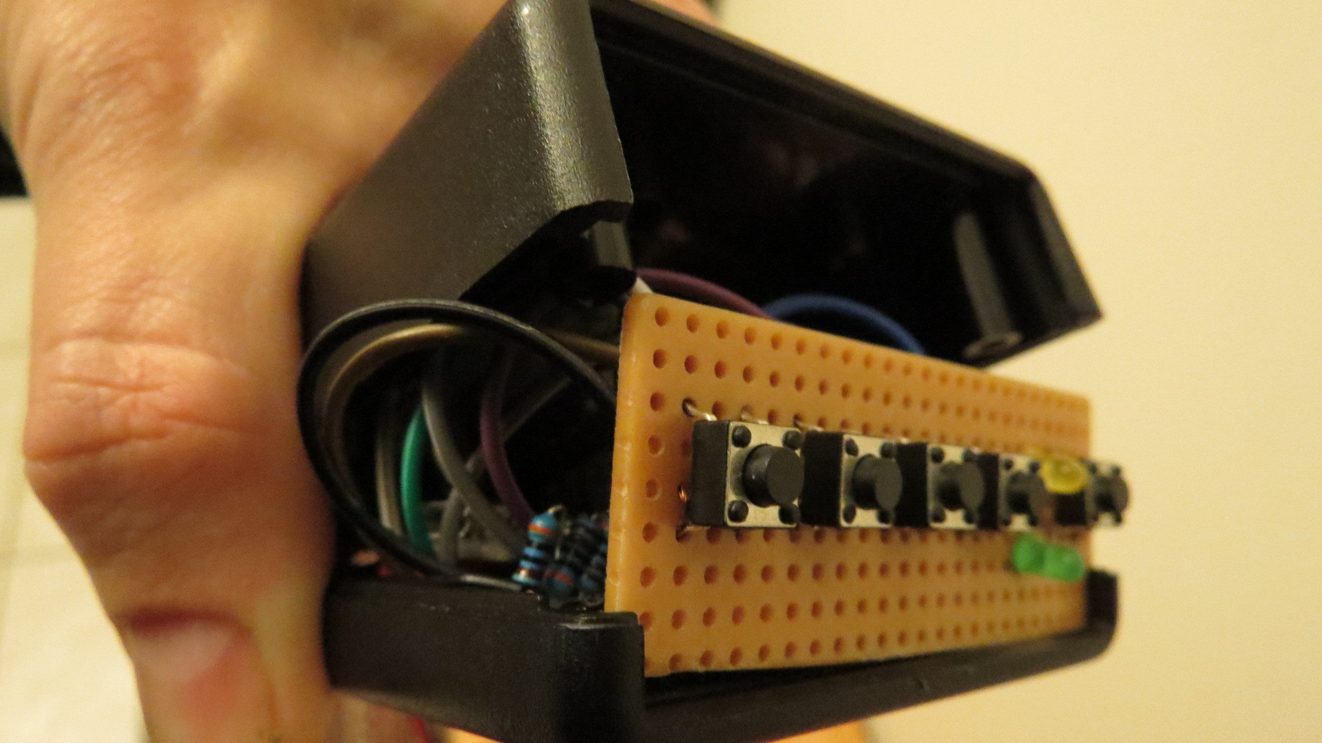
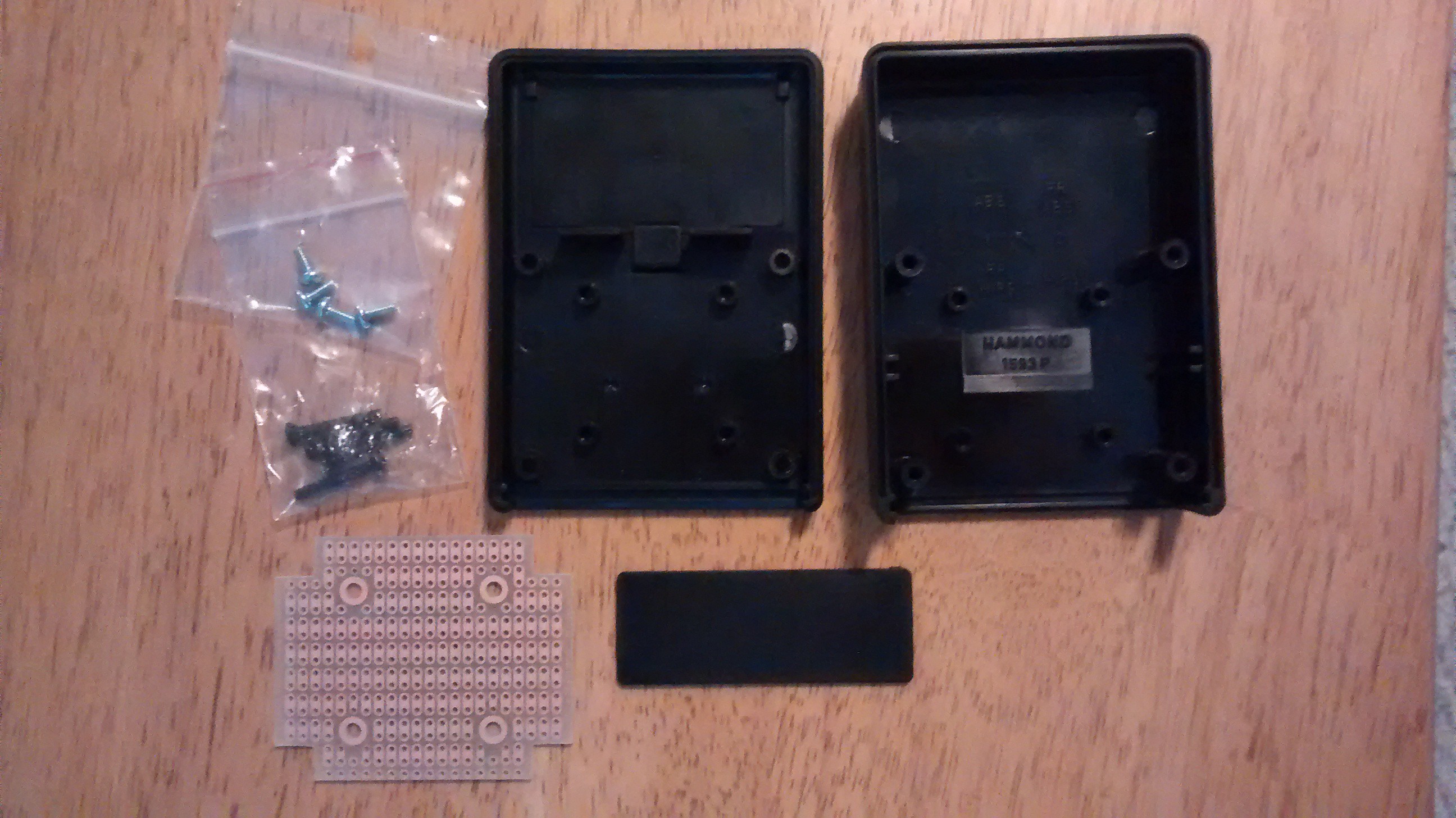
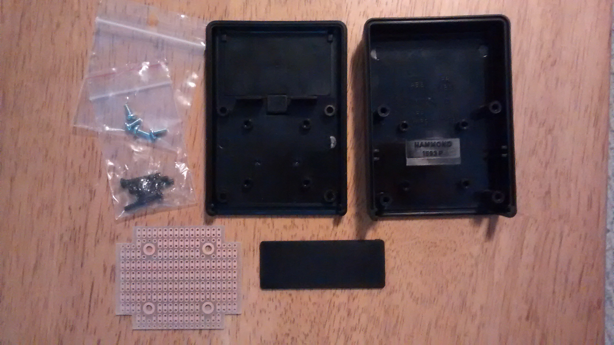
    I then took the PCB, the perf board with the buttons, and put it into a project box I had ordered specifically for this project. This was the project box, which included a custom PCB to fit into the box.

    I then had to squish the wiring, the alarm, and the PCB into the project box, which proved to be a little bit of a challenge. I managed to get it, but really had to work to fit it in, and bend the wires in the right way.

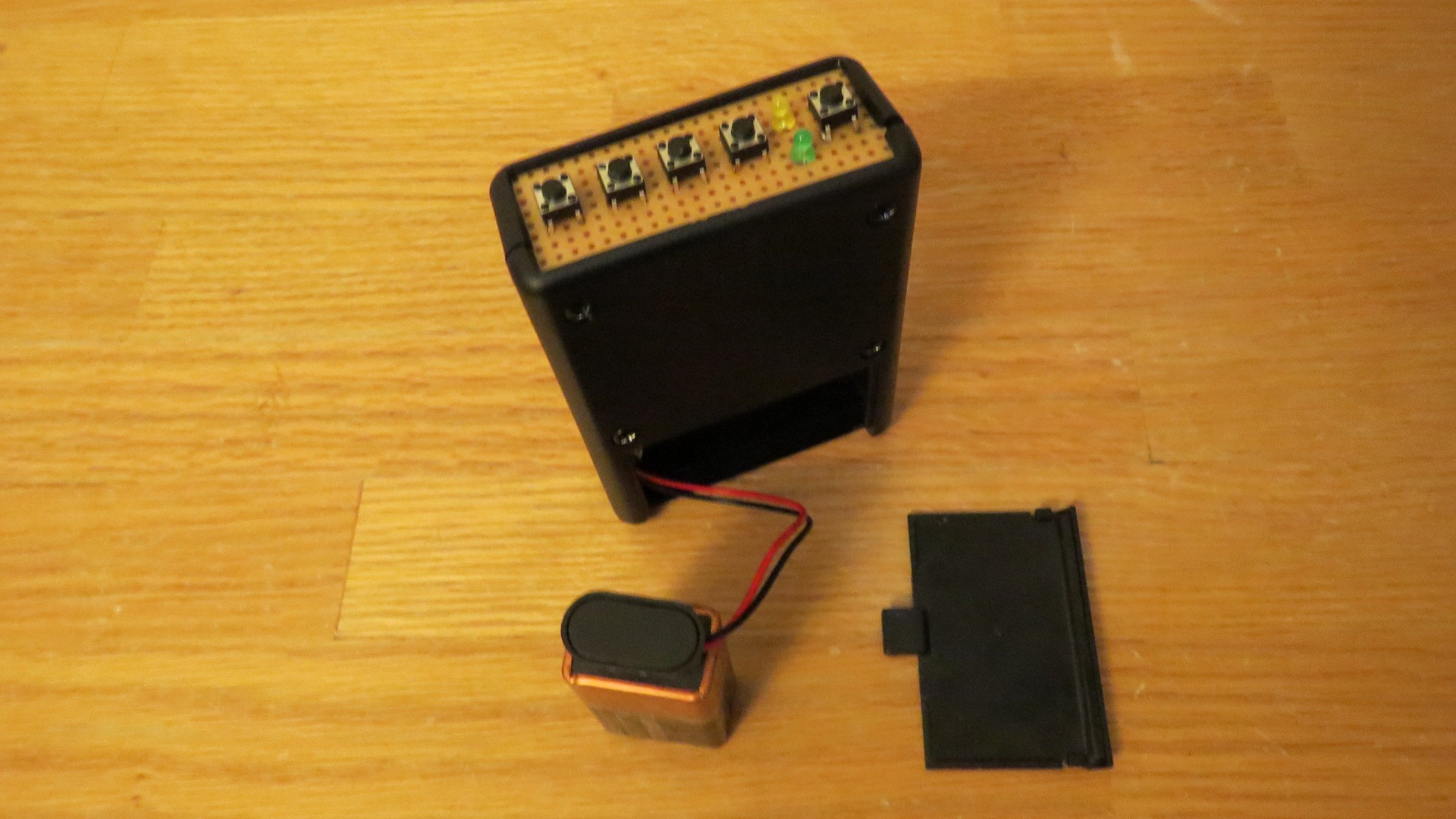
    Then I screwed it shut and tested it out! Works like a charm.

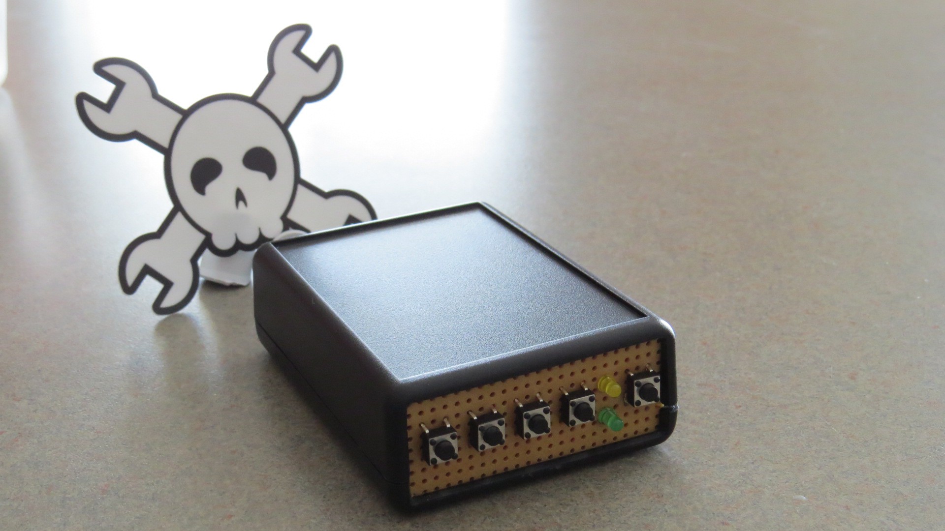
    The completed project:

  • Soldering complete!

    MakerSelf12/27/2014 at 08:20 1 comment

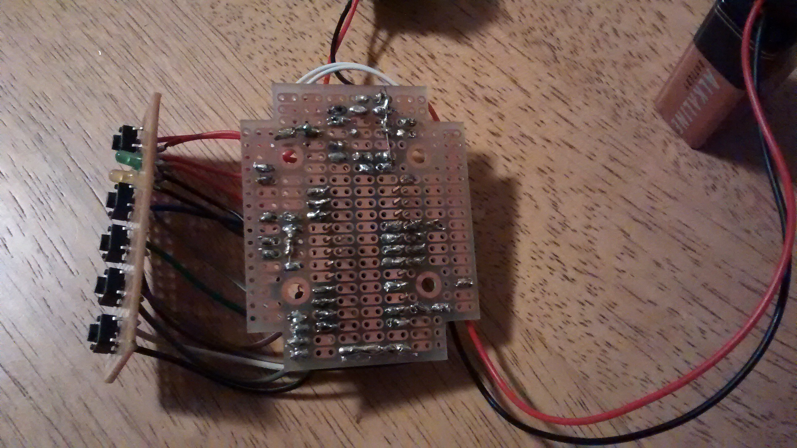
    I thought for a little while it wouldn't all fit, but I managed to squeeze the entire prototype onto a small little PCB that will fit into a project box that I have, with the buttons and LEDs on a bit of perf board that will replace one of the ends of the box.

    It took me sometime to figure out how to lay it all out (I took a picture of the blank PCB, printed it out, and drew on it), and then it took a solid day and a half to actually do the soldering (thankful for holidays right now!). There were a few moments were I thought I had screwed it up, and it is a bit of a leap of faith because you need to wait until it is all done until you can really test it.

    BUT, it is finished, and it works!

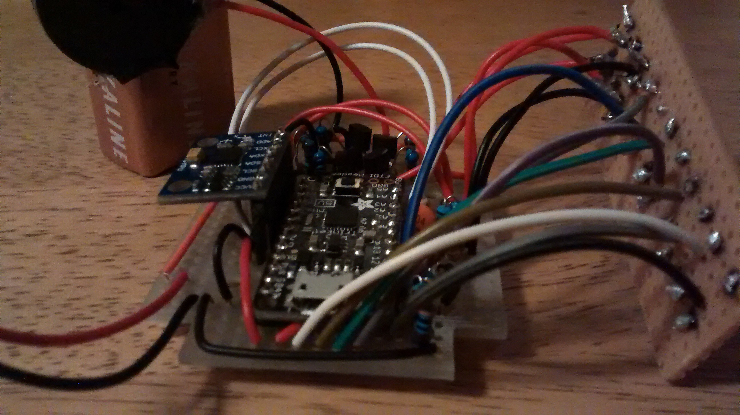
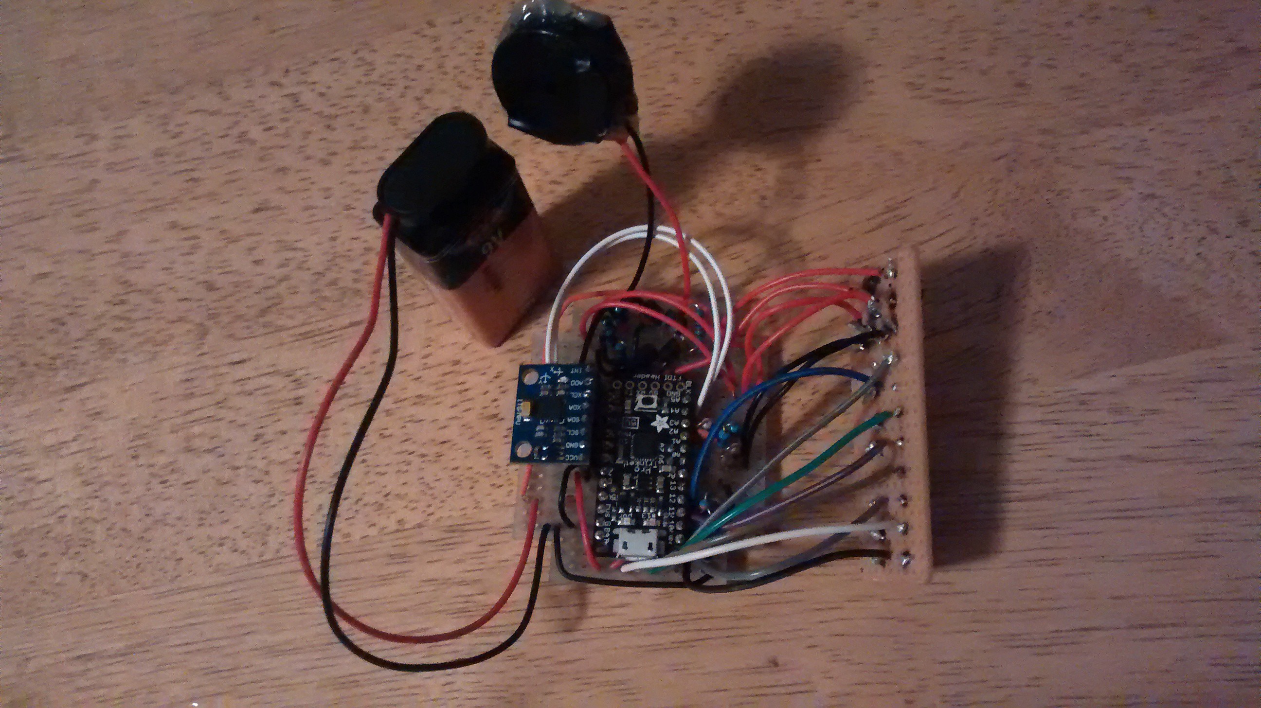
    You can see most of it in the pictures. There are a number of wires running underneath the TrinketPro, which was the last thing to be added.

    And a video of it in action:

  • Prototype Complete!

    MakerSelf12/26/2014 at 10:05 0 comments

    Okay, so a lot has happened since my last project update:

    1) Integrated the TrinketPro into the project. I needed to change my sketch a bit, but the big issue was that with the TrinketPro the power circuit no longer works. I just couldn't find a resistance level that would keep the processor off normally, but allow the transistor to keep it on.

    2) Redesigned the power circuit. Some web poking and a post on the Arduino forums helped solve this issue. Solution was to utilize a p-channel MOSFET along with an n-channel MOSFET, using this as the inspiration:

    3) Added a battery power monitor circuit and sketch. I use a voltage divider (two equal resistors) to bring the voltage below 5v, and then use an analog in pin to measure the voltage (x2 to get the actual voltage). Crude, but functional, and really it is just a low battery warning.

    4) Added some UX elements to the sketch (e.g. when it is armed, can enter the code to shut it off without triggering the alarm).

    The completed circuit is below, as is a video of it in action.

    From the top:

    And a close up:

    A video of it in action:

  • TrinketPro arrived!

    MakerSelf12/22/2014 at 01:44 0 comments

    My Trinket Pro arrived!!

    Looks pretty cool, especially with that black Hackaday mask on it!

    TrinketPro... a little small, but packs an Uno punch!

    I ordered one from the hackaday store, and it came without headers soldered on, so I soldered them right on, including a short two pin header on the A6 and A7 pins (the location of these two pins is inside from the edge, and as a result when in a breadboard these two pins will be the same as A0 and A1. In a perf board, these could be separate).

    The first step was to see if I could program it. This proved to be a bit of a challenge.

    The introduction pdf was extremely helpful, as was the overview from Adafruit.

    There were three challenges:

    1) Adding the Trinket Pro as an eligible board. I needed to download the boardfile from Adafruit, and extracted to a folder that I put in the my Arduino folder (end result: arduino/hardware/Trinket Pro/boards.txt).

    2) Utilizing the USBtinyISP driver to install via the USB drive (instead of the FTDI header). I tried downloading the driver from Adafruit and installing it on my Windows machine, but it would not install. The install window would just flash briefly and then disappear, as if there was nothing to install. I tried several times. Luckily, I also have an old MacBook Pro which already has USBtinyISP installed. So, instead of using my Windows machine, I needed to transfer files to my MacBook and then I could program the TrinketPro. It also labeled the serial ports differently than on my Windows machine: instead of "COM6″ etc., it used "/dev/cu.Bluetooth-PDA-Sync".

    3) Timing the programming. The TrinketPro requires that you press the reset button to put it into the bootloader mode, and then you have window of time to upload a new program before is goes into running the current program on the board. I found that if I pressed the reset button on the TrinketPro and then pressed the upload button on the IDE, the compile would take too long and the bootloader would exit before the uploading began. I needed to press the upload button in the IDE on the computer, wait a second or two, and then press the reset button on the TrinketPro to get into bootloader mode. If I did that, the sketch would upload successfully!

  • Integrated the accelerometer

    MakerSelf12/21/2014 at 08:28 0 comments

    I finally got the accelerometer delivered, and I wanted to integrate it into the circuit and the code.

    I first experimented with the accelerometer as a separate entity, and then once I had developed a working code for the accelerometer, integrated it into the main alarm box code.

    The big challenge was not reading the accelerometer raw values or putting in a sensitivity to determine if it has moved, but for telling how LONG there has been movement, and only if there is movement for say 5 seconds does it trigger the alarm… if it is moving for longer than 5 seconds then it has been stolen! The difficult part is that there may be moments in there where there is no movement, e.g. for a half second it may stop but then start moving again, and I don't want that to 'reset' the movement time counter.

    Here is the approach:

    1. I would store the "moved" value in an array, shifting the new one in each time I take a reading. Since I have the sensor reading at 1/4 of a second right now, to store the previous 5 seconds of "moved" would take 20 elements. Each time I read a sensor value, I drop the oldest one, and add the newest one to the array.
    2. I would then look to see if there is a more than 5 second period between two moments of movement (i.e. it has been potentially been moving for more than 5 seconds). As if I only stored 5 seconds of data and the alarm only goes off if there is more than 5 seconds of movement, it would only go off if the very first and the very last elements in the array were recorded as moved, I needed to store MORE than the movement time. I decided to store the previous 10 seconds of data, and look at any more than 5 second period in that.
    3. Then, I would loop through each element of the array and count how many are "moved" and how many are "not moved" between those two moments of movement, to see if it exceeds a threshold amount (say I allow 20% not movement before).

    This way, there would be two tests:

    1. Does the time between the oldest "moved" and the newest "moved" exceed 5 seconds? (i.e. it has potentially been moving for more that 5 seconds)
    2. If so, does "moved" exceed the threshold value for that time period? (i.e. it has actually been moving)

    I can thus exclude the two events I want to exclude:

    1. Two blips more than 5 seconds apart, but with little movement in between (below the threshold).
    2. Movement (even 100% of the time) of say 4 seconds, and then stop.

    I would only include it as "stolen" if:

    1. There are two blips of movement more than 5 second apart (with some maximum time period between moments of movement)
    2. AND there has been movement above the threshold in between those two blips (e.g. 80% of the time it has been moving)

  • Button based security code

    MakerSelf12/16/2014 at 04:55 0 comments

    The last update was talking about the steps to build the circuit, and this is about using the circuit. I needed to program it so that when you pressed the arm button, it would turn on. A event (in the final product, movement) would trigger the alarm, and then the code would turn it off.

    I built this up over the course of a few days, starting with a simple version using delays, and then building out the button based security code utilizing non-blocking code. I was very happy with the result, and stripped out some the unnecessary pieces for the power circuit component, and posted it to the Ardunio.cc forum (see the post) as a standalone button based security code sketch. Hoping to get some feedback, and also wanted to share in case someone wanted to do something similar.

    I have posted the code as it stand so far (includes the power on, and the button based code) below, but also wanted to share a video of it operational so far:

    The code (the comments make it a little difficult to follow, sorry!)

    /* alarmbox.ino
    
     Implements a security code using buttons as the way to input the code.
     Number of buttons, the number of digits in the secret code, and the 
     numerical value of each button (for the code) can be defined independently.
    
     This code can be used to take any action when the secret code is entered
     correctly.  In this example, the on board LED is on while the secret code 
     has not been correctly entered, and then is turned off when the secret 
     code is entered correctly.
    
     The sketch also prints the code that has been entered so far to the serial
     monitor, along with if it has been matched (only when matched). 
     
     There is no need for resetting the code entered periodically as the code
     entered is simply made up of the last X number of digits that had been
     entered (X depends on the length of the secret code).  
     
     The circuit: 
     * If no LED on the board that is attached to pin 13, attach an LED from
     pin 13 to ground
     * For each button you choose to have for inputs into the entered code 
     (in this sketch there are four buttons, but you can change that):
      -- Use a normally open button (i.e. only on when you press it, then it pops up)
      -- Connect from one side of the button to ground through a resistor 
         (A decent size, in this example 1k resistors were used but you can use 10k 
         or similar larger value.)
      -- Connect from the other side of the button to a digital I/O pin on the
         arduino board. (in this sketch, button 1 was connected to pin 8,
         button 2 to pin 9, button 3 to pin 10, button 4 to pin 11, but you can
         change that as long as you change it in the sketch (noted where you do
         that).
     
     Created December 2014
     by MakerSelf (makerself.wordpress.com)
     Please use, modify and be merry!
    
    */
    
    //========================================
    
    // --------CONSTANTS---------------
    const int secretCodeLength = 7;
    const int secretCode[secretCodeLength] = {1, 2, 3, 4, 3, 2, 1};
    const int codeEnteredInitializedValue = 0;
    
    const int numberOfButtons = 4;
    const int buttonPins[numberOfButtons] = {8, 9, 10, 11};    //put your pins here
    const int buttonValues[numberOfButtons] = {1, 2, 3, 4};    //put the values of the button you want to use here
    const int buttonInterval = 300;                            //this is the sensitivity of the button (i.e. how quickly can you double press the button)
    const byte buttonPressedState = LOW;
    const byte buttonNotPressedState = HIGH;
    
    const int OnOffPin = 7;
    const int speakerPin = 6;
    
    //------------ VARIABLES---------------------
    int codeEntered[secretCodeLength];                       //this gets initilized
    byte buttonStates[numberOfButtons];                      //this gets initilized
    unsigned long previousButtonMillis[numberOfButtons];     //this gets initilized
    byte speakerState;
    
    unsigned long previousSerialMillis;                      //for debugging or printing to the serial if that is the objective.  Gets initialized to zero when begin Serial Communication.
    
    
    // ==================================================================================
    
    // --------MAIN PROGRAM---------------
    void setup() {
     //turn the...
    Read more »

  • Building more pieces of the circuit: adding buttons and piezo speaker

    MakerSelf12/16/2014 at 04:44 0 comments

    For this project, I need to have a secret security code that can shut off the alarm. I wanted to have this be very simple, so just use a multi button interface. For the project, I decided to chose 4 buttons.

    So I built on top of the power circuit I wrote about in the last project update, to add both the buttons and the speaker.

    To add the buttons, I connected one side to the positive power rail through a resistor (1K), and the other side directly to the ground rail. If I connected it the other way (through a resistor to ground, and the other side to the positive rail), then the ground would be connected to the board through the resistor, and it would turn on before I wanted it to (before the power button had been pressed). I also put in a 47k resistor between the button and the input pins on the board, as otherwise the code buttons would be able to turn the board on (I want to only be the power / arm button that does this)

    To add the speaker, I utilized a 2n3906 transistor, with the base connected to a PWM output pin via a variable resistor (I used a 100k pot). I needed the resistance else the board would turn on automatically. I connected the source to ground, the drain to the negative side of a small piezo speaker, and the positive side of the piezo speaker to the positive power rail / the +5V out of the Uno I am prototyping this with until my Trinket Pro arrives.

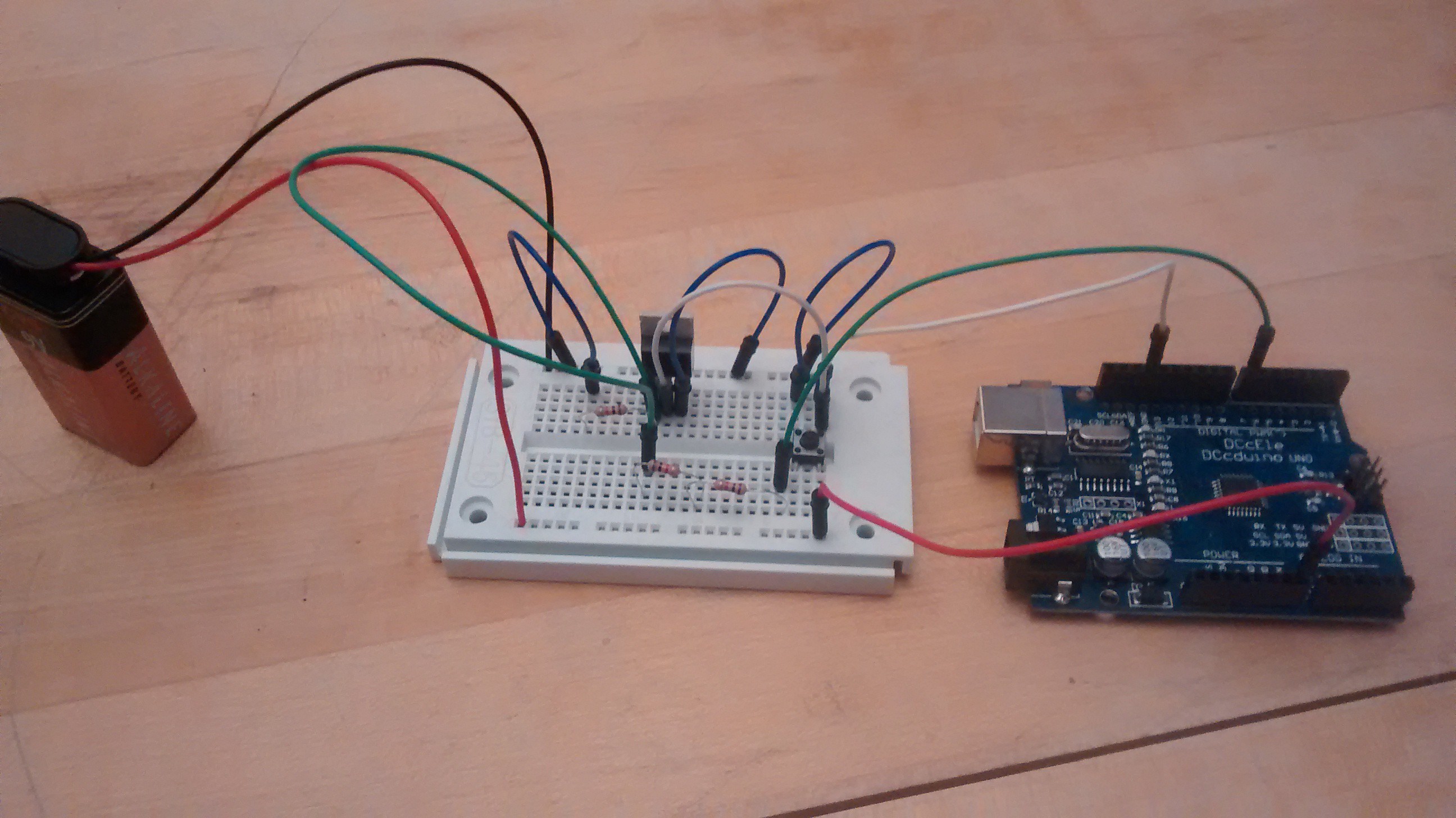
    Here is a picture of the circuit when finished on the breadboard:

    I am still missing the Trinket Pro, the accelerometer, and a better speaker.

  • Power circuit designed!

    MakerSelf12/11/2014 at 04:28 0 comments

    While I am waiting for my parts to arrive, I decided to work on designing the power circuit of the project.

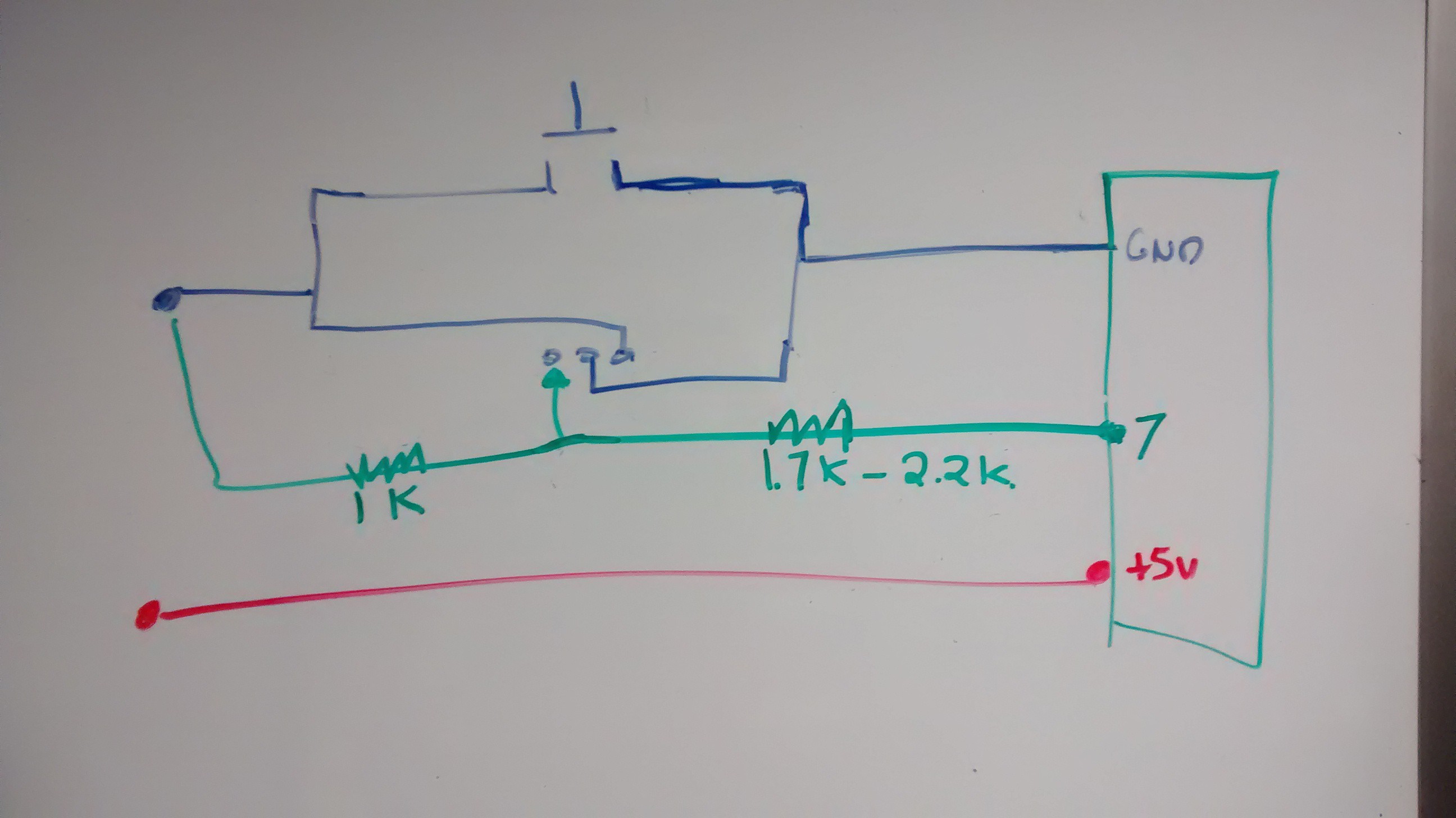
    A key part of the project is that you can hit a button to turn the board on, but hitting the button again does not turn it off. This is to prevent the thief from being able to turn the alarm off by simply hitting the on/off switch. I also wanted to have it so that the device would completely power off when not in use, not in a sleep mode or similar waiting for the arm button to be pressed.

    I decided to make a circuit where the power from the battery would flow to the board by one of two ways:

    1) a button

    2) a transistor, which is controlled by digital pin on the microcontroller

    The basic schematic is below: (the 7 is just because I used that pin when testing the circuit)

    The transistor is an N-channel power MOSFET transistor, available here: https://www.adafruit.com/products/355?&main_page=product_info&products_id=355

    Way over kill for this project, but it was what I had on hand. I imagine I can replace it with a ZVN2110A, which I can get from Mouser for less than a dollar. I anticipate relatively low current needs for this project, so that transistor should be able to handle it.

    I also put in a 1k resistor to tie the gate of the MOSFET to ground (which was expected, and designed to keep that part of the transistor circuit normally off), but was not expecting to need to put in resistors between the digital pin on the microcontroller and the MOSFET gate. After some experimentation, I found that a resistor of between 1.7k and 2.2k did the trick. So I put in two 2k resistors when I constructed the circuit on the breadboard.

    In the sketch, I have the digital pin that is tied to the MOSFET gate (in my case, pin 7) pulled to HIGH in the setup, so the MOSFET gate opens nearly as soon as the button is pressed. When the button is depressed, the MOSFET remains on and power continues to flow to the board. Further presses of the button have no impact. The circuit stays on until I decide to put the pin LOW, turning off the circuit completely and de-powering the board. In the test circuit, this occurred 5 seconds after the board turns on, but in the actual project I will program it to do so only when the correct 4-digit code has been punched in.

  • Components ordered!

    MakerSelf12/08/2014 at 05:32 0 comments

    I ordered the components that I am missing!

    Ordered:

    - 1x Trinket Pro from Hackaday.io (the screenprint looks badass)

    - 1x MPU 6050 accelerometer

    - A variety of small plastic boxes and project boxes from Amazon. I would like to put this in a small container, and eventually will try to 3D print this (but that will likely occur in the new year).

    - Some nice, big momentary on buttons (5), also from Amazon

    I have the LED, some other buttons should I need, the transistor etc. already. Just hoping the components don't take too long to arrive so I will be able to get down to working on the project.

View all 10 project logs

  • 1
    Step 1

    Step 1: Gather your componenets

    Obtain / purchase the following components:

    • 1x Trinket Pro. You can get one at the Hackaday store.
    • 1x Accelerometer. You can use a variety, but I used the GY-521 available here.
    • 1x Project box. I used a project box with an integrated PCB and battery compartment, available here.
    • 1x Piece of perf board (doesn't need to be very big, just enough to cover one end of the project box)
    • 1x Buzzer. You can use various depending on your preference for sound, but I used this one from RadioShack. I chose it based on the loud sound but low current consumption, and that it takes a broad range of voltages (3V-28V) so I wouldn't need to be too fussy about battery voltage.
    • 2x P-Channel MOSFET transistor. From Mouser here. These are TO-92 packages, so fairly small. The max current is below what I anticipate would ever be needed to power all the components.
    • 2x N-Channel MOSFET transistor. From Mouser here.
    • 2x 330 ohm resistor (for current limiting on the LEDs)
    • 12x 10k ohm resistor (for ground ties, etc.)
    • 1x 47k ohm resistor (for current limiting for the battery monitor pin)
    • 1x 100nF capacitor (for dealing with any spikes on the battery monitor pin)
    • 1x Green LED
    • 1x Yellow LED
    • 5x momentary on push buttons. Your choice of style and size!
    • 1x 6 pin female header
    • 2x 12pin male headers (for the Trinket Pro, and may come with your Trinket Pro)
    • 1x 9V battery clip
    • 1x 9V battery
    • Hook up wire (multi color if you want to keep things straight for yourself)
    • some thin foam padding (e.g. from envelope padding). Optional, to make the battery fit more snug.


  • 2
    Step 2

    Step 2: Get your tools

    To complete this project you will need:

    • Soldering iron and solder
    • Hot glue gun
    • Dremel or similar saw (for cutting the perf board)
    • File (for filing the cut perf board)
    • Helping Hands and tweezers, for helping to hold and place the components
    • Wire snips
    • Wire stripper
    Pic of some of the components:


  • 3
    Step 3

    Step 3: Plan how to lay out the components on the board

    I had to think about how to lay out the board. The board I used came with the project box, which you can see here:

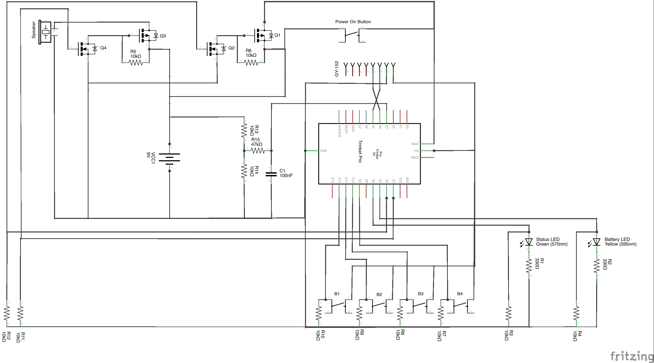
    The schematic of the project is here:

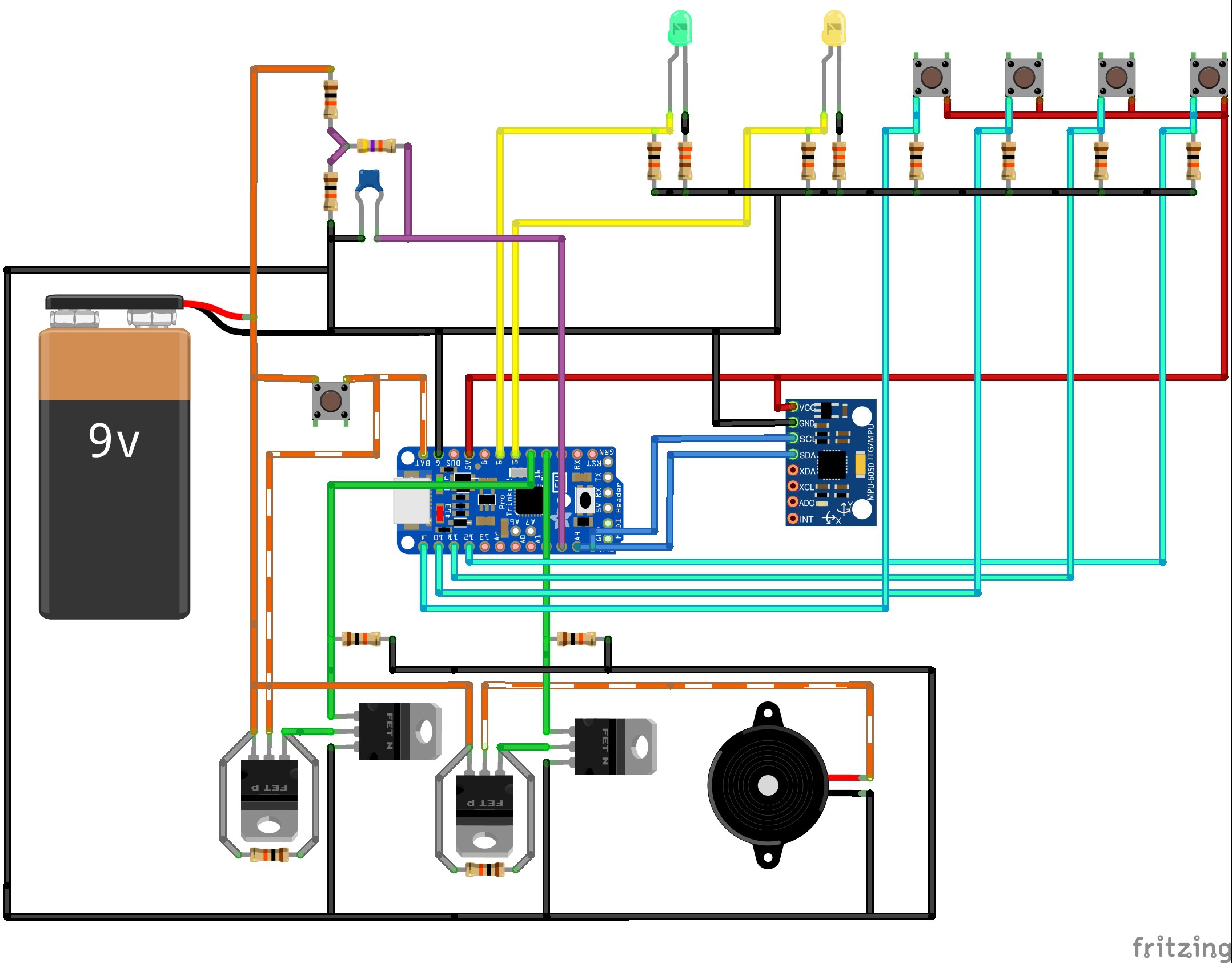
    And a picture of how all the components are connected is here:

    Note in the diagram above, I have used orange to indicate 9V rail (stripped indicates that it is only sometimes on), and red to indicate 5V rail. Ground is consistent as black. Yellow connects to the LEDs, Cyan to the push buttons, purple is the input to the battery monitor pin, blue is the SCL and SDA for the accelerometer, and green are the two switching pins (to turn the power circuit on and the speaker on.

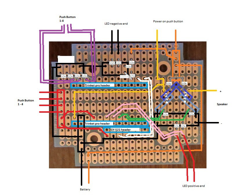
    Since the board is fairly small, I laid all the components out on the board by drawing it out on a piece of paper (just made it easier). The end result is below:

    The two headers for the Trinket Pro are marked in the light blue boxes, with the USB port for the Trinket Pro pointed to the left. The headers I used on the Trinket Pro had enough space so I could run wires underneath it (you can see the gold, green, pink, red wires all underneath the board. These components and wires are actually placed on the OTHER side of the board, with the soldering on this side. For the GY-521, I actually soldered on a header, and then put the GY-521 into the header. I had enough head room (barely) in the project box to do this and it made it easier to fit the wires underneath the GY-521.

    The grey lines are passive components, and are marked appropriately.

    The black, red and orange squares are ground, +5V and +9V rails. You will need to solder all connections in this square together.

    The transistors are in a arrow head pattern, allowing the drain of the N-Channel MOSFETS to go directly to the gate of the P-Channel MOSFET. The top of the arrow head is the common source (+9V) for the two P-Channel MOSFETs. With the TO-92 packages, the P and N MOSFET pairs should either face each other or have their backs to each other. The left ones should face each other (rounded part towards rounded part) and the right ones should have backs to each other (flat part towards flat part). Confirm the pin layout for your transistors.

    The five buttons and the two LEDs go on a piece of perf board that would replace the end piece of the project box was removable (see the small black rectangular piece in the project box picture above. Where those connections are (buttons and LEDs) are marked on the diagram above. Additional external connections are the battery + and - from the battery clip, and the speaker would just hang loose and be stuffed in on top of the Trinket Pro when closing up the box.


View all 15 instructions

Enjoy this project?

Share

Discussions

MakerSelf wrote 01/01/2015 at 21:39 point

Thanks, much appreciated!

Will post a video of the final project in action shortly!

  Are you sure? yes | no

Mehmet-cileli wrote 01/01/2015 at 20:45 point

well done good idea

  Are you sure? yes | no

Similar Projects

Does this project spark your interest?

Become a member to follow this project and never miss any updates