-
1Step 1
Step 1: Gather your componenets
Obtain / purchase the following components:
- 1x Trinket Pro. You can get one at the Hackaday store.
- 1x Accelerometer. You can use a variety, but I used the GY-521 available here.
- 1x Project box. I used a project box with an integrated PCB and battery compartment, available here.
- 1x Piece of perf board (doesn't need to be very big, just enough to cover one end of the project box)
- 1x Buzzer. You can use various depending on your preference for sound, but I used this one from RadioShack. I chose it based on the loud sound but low current consumption, and that it takes a broad range of voltages (3V-28V) so I wouldn't need to be too fussy about battery voltage.
- 2x P-Channel MOSFET transistor. From Mouser here. These are TO-92 packages, so fairly small. The max current is below what I anticipate would ever be needed to power all the components.
- 2x N-Channel MOSFET transistor. From Mouser here.
- 2x 330 ohm resistor (for current limiting on the LEDs)
- 12x 10k ohm resistor (for ground ties, etc.)
- 1x 47k ohm resistor (for current limiting for the battery monitor pin)
- 1x 100nF capacitor (for dealing with any spikes on the battery monitor pin)
- 1x Green LED
- 1x Yellow LED
- 5x momentary on push buttons. Your choice of style and size!
- 1x 6 pin female header
- 2x 12pin male headers (for the Trinket Pro, and may come with your Trinket Pro)
- 1x 9V battery clip
- 1x 9V battery
- Hook up wire (multi color if you want to keep things straight for yourself)
- some thin foam padding (e.g. from envelope padding). Optional, to make the battery fit more snug.
-
2Step 2
Step 2: Get your tools
To complete this project you will need:
- Soldering iron and solder
- Hot glue gun
- Dremel or similar saw (for cutting the perf board)
- File (for filing the cut perf board)
- Helping Hands and tweezers, for helping to hold and place the components
- Wire snips
- Wire stripper
![]()
-
3Step 3
Step 3: Plan how to lay out the components on the board
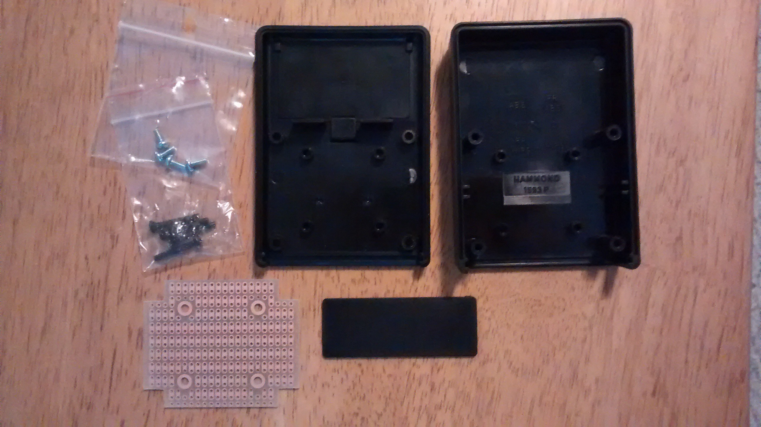
I had to think about how to lay out the board. The board I used came with the project box, which you can see here:
![]()
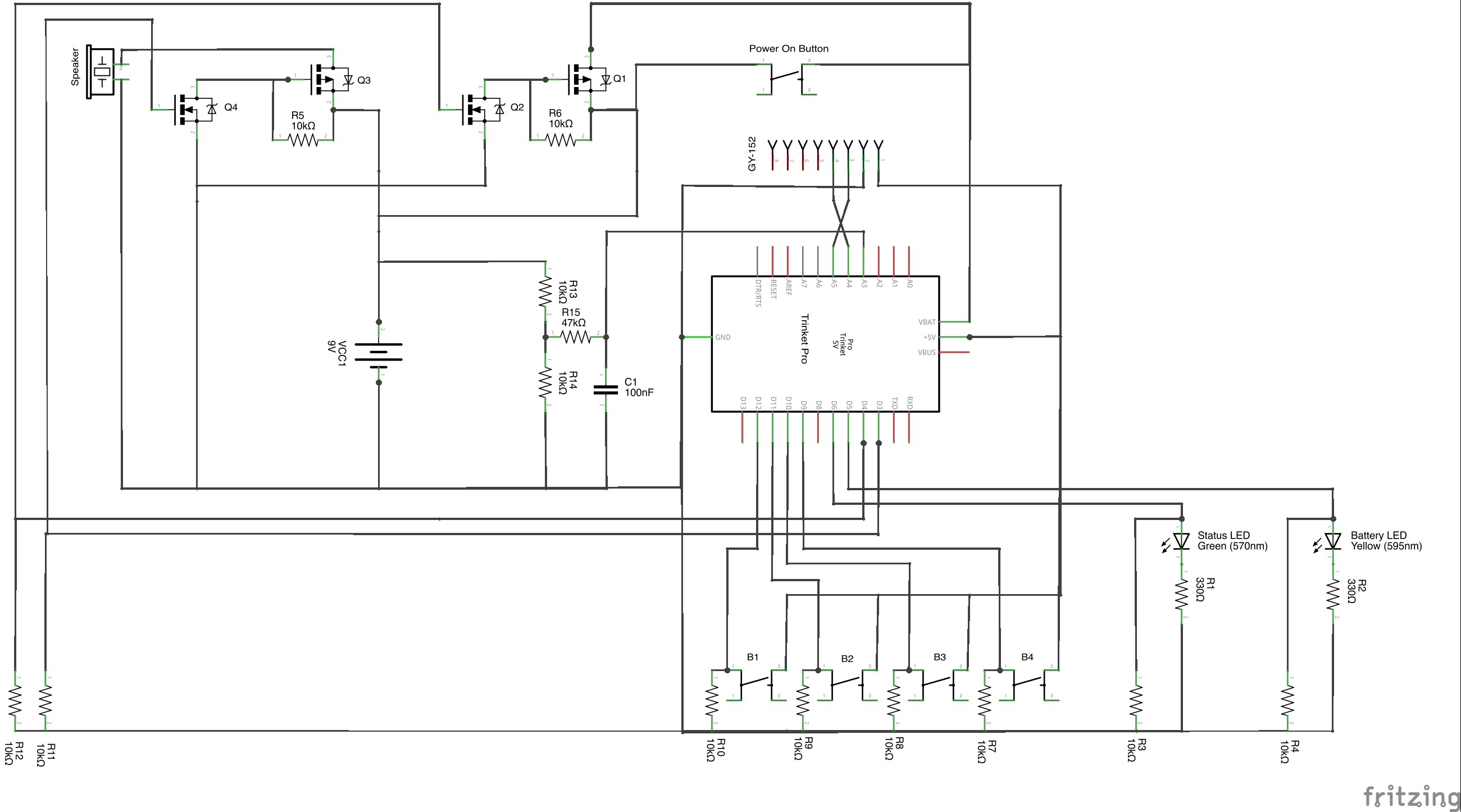
The schematic of the project is here:
![]()
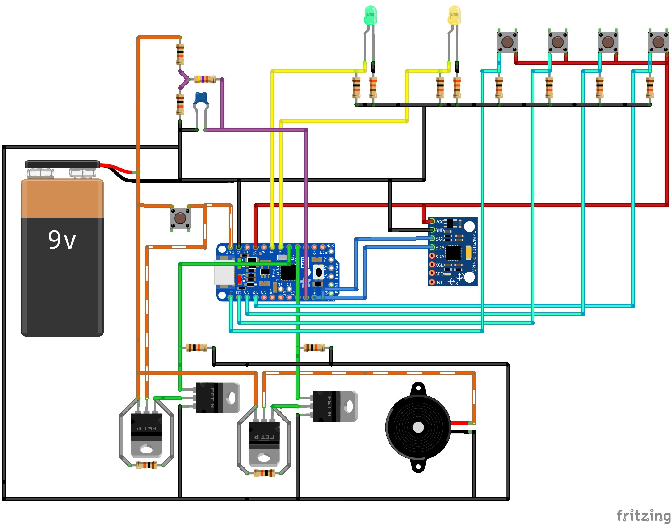
And a picture of how all the components are connected is here:
![]()
Note in the diagram above, I have used orange to indicate 9V rail (stripped indicates that it is only sometimes on), and red to indicate 5V rail. Ground is consistent as black. Yellow connects to the LEDs, Cyan to the push buttons, purple is the input to the battery monitor pin, blue is the SCL and SDA for the accelerometer, and green are the two switching pins (to turn the power circuit on and the speaker on.
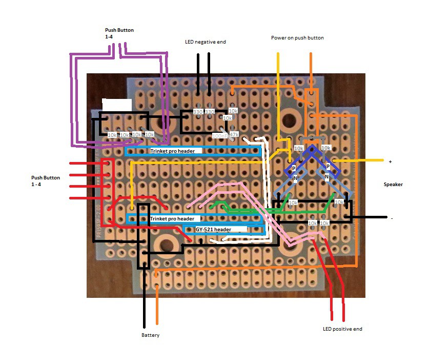
Since the board is fairly small, I laid all the components out on the board by drawing it out on a piece of paper (just made it easier). The end result is below:
![]()
The two headers for the Trinket Pro are marked in the light blue boxes, with the USB port for the Trinket Pro pointed to the left. The headers I used on the Trinket Pro had enough space so I could run wires underneath it (you can see the gold, green, pink, red wires all underneath the board. These components and wires are actually placed on the OTHER side of the board, with the soldering on this side. For the GY-521, I actually soldered on a header, and then put the GY-521 into the header. I had enough head room (barely) in the project box to do this and it made it easier to fit the wires underneath the GY-521.
The grey lines are passive components, and are marked appropriately.
The black, red and orange squares are ground, +5V and +9V rails. You will need to solder all connections in this square together.
The transistors are in a arrow head pattern, allowing the drain of the N-Channel MOSFETS to go directly to the gate of the P-Channel MOSFET. The top of the arrow head is the common source (+9V) for the two P-Channel MOSFETs. With the TO-92 packages, the P and N MOSFET pairs should either face each other or have their backs to each other. The left ones should face each other (rounded part towards rounded part) and the right ones should have backs to each other (flat part towards flat part). Confirm the pin layout for your transistors.
The five buttons and the two LEDs go on a piece of perf board that would replace the end piece of the project box was removable (see the small black rectangular piece in the project box picture above. Where those connections are (buttons and LEDs) are marked on the diagram above. Additional external connections are the battery + and - from the battery clip, and the speaker would just hang loose and be stuffed in on top of the Trinket Pro when closing up the box.
-
4Step 4
Step 4: Cut the perf board
The easiest way to mount the buttons was to cut a piece of perf board the same size as the end piece for the project box.
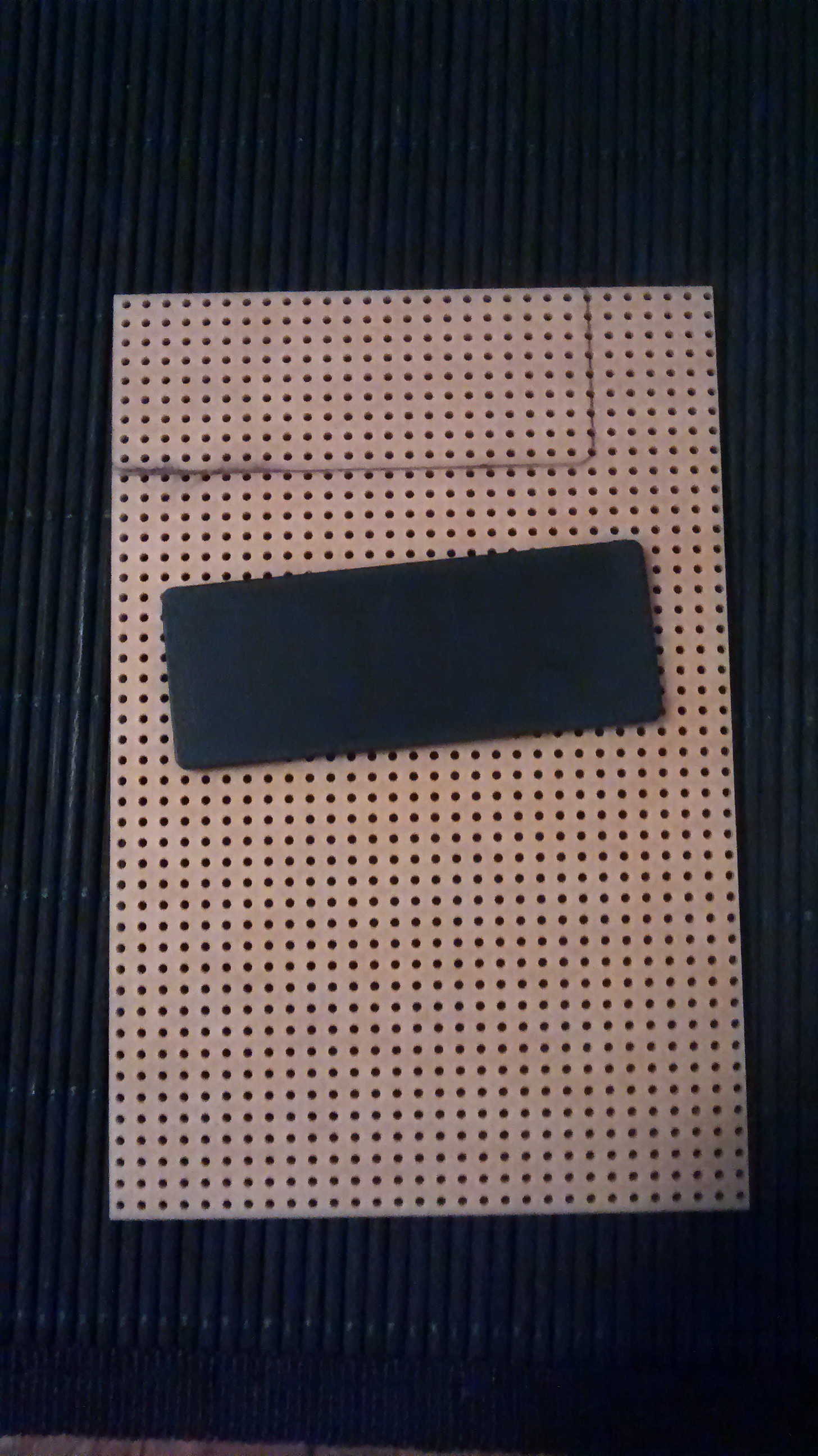
To do this, I traced out the piece from the project box on a piece of perf board:
![]()
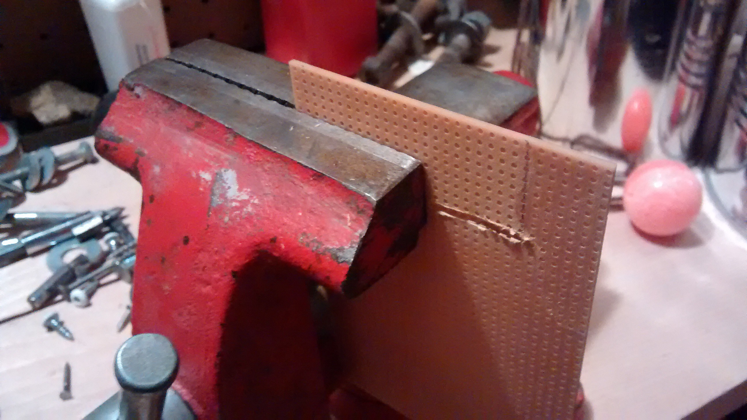
And then cut it with a dremel:
![]()
![]()
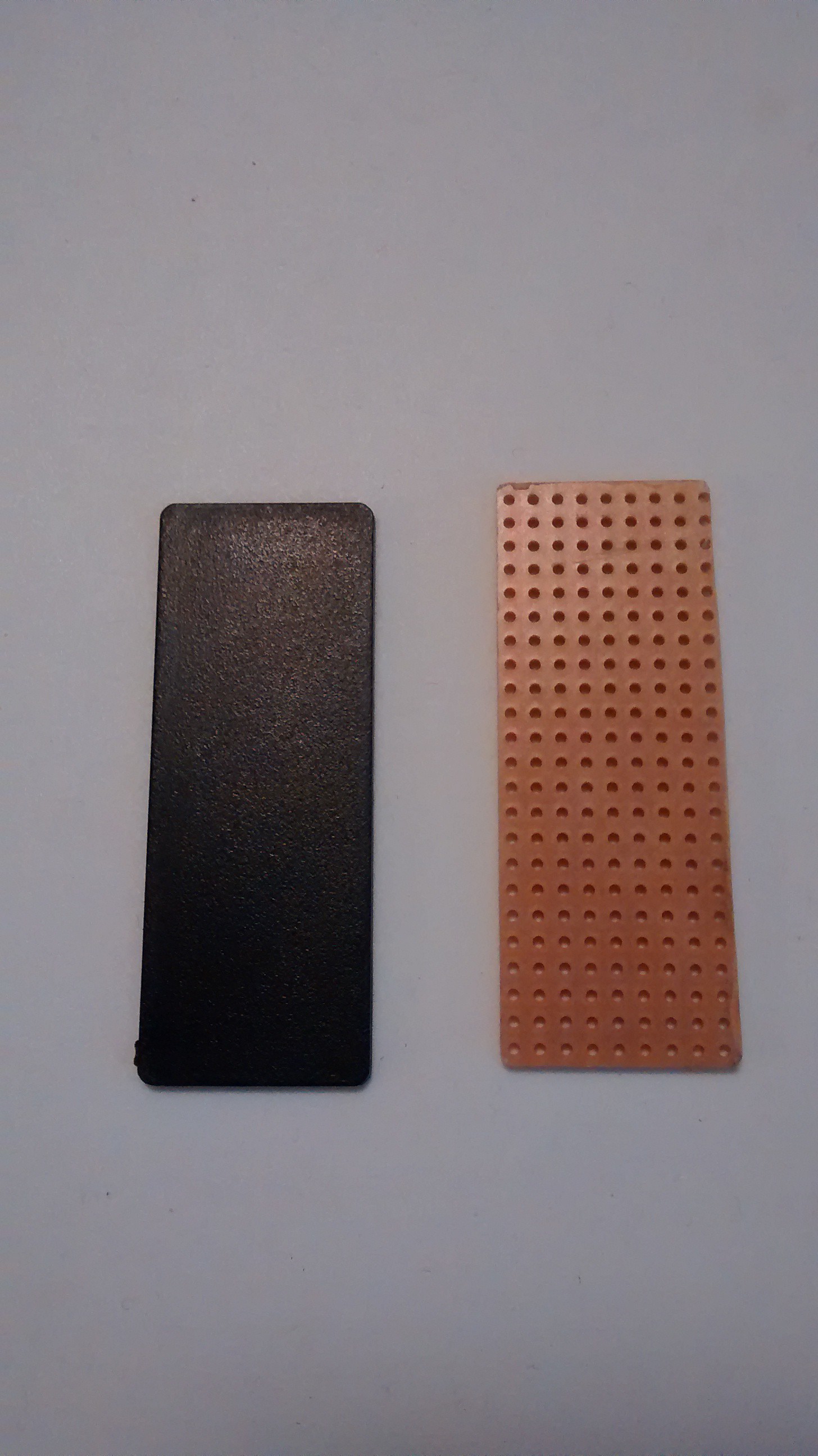
And then filed the perf board so it matched the piece from the project box pretty exactly:
![]()
The end result:
![]()
And finally test it to see that it fits in the project box:
![]()
-
5Step 5
Step 5: Solder the perf board
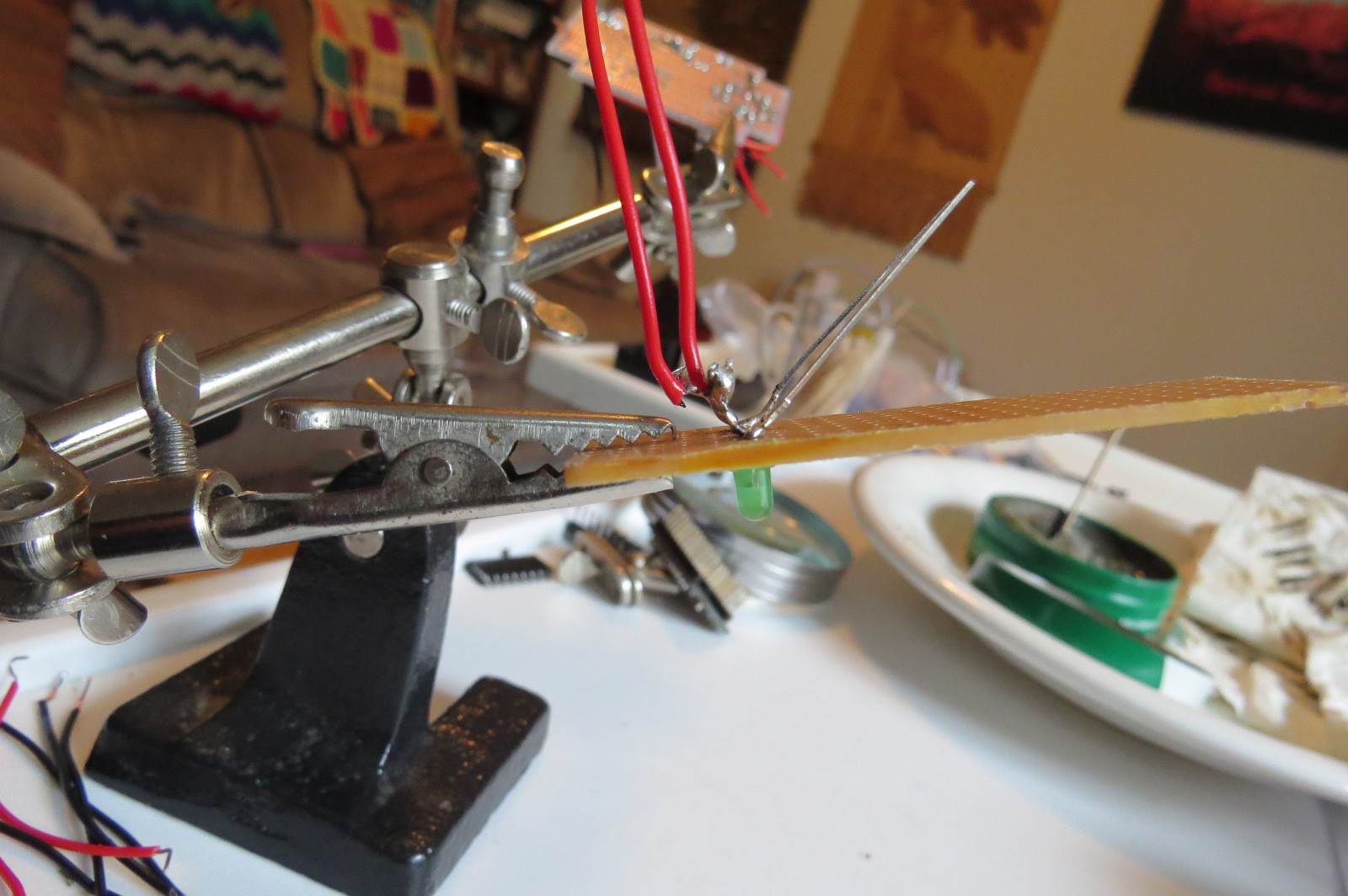
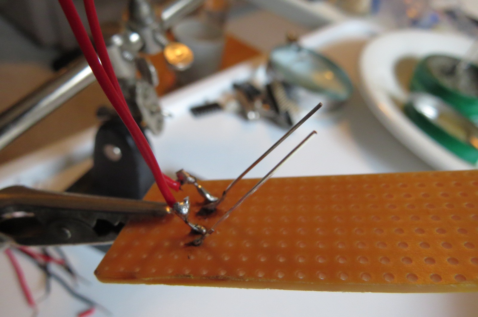
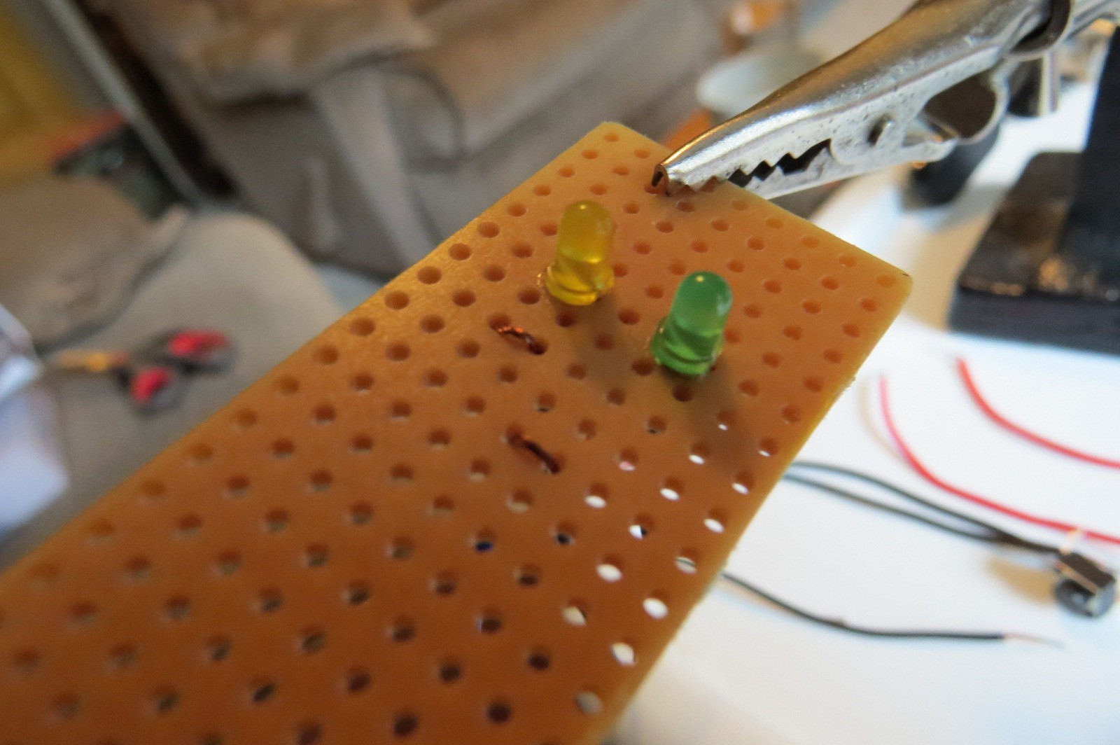
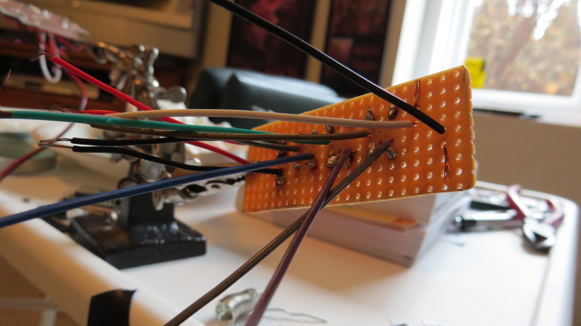
It is easier to solder to the components on the perf board first, and then solder the other end of the wire to the project board.After laying out the buttons and the LEDs on the perf board, I first soldered the LEDs: (excuse the abundant and poor quality soldering!):
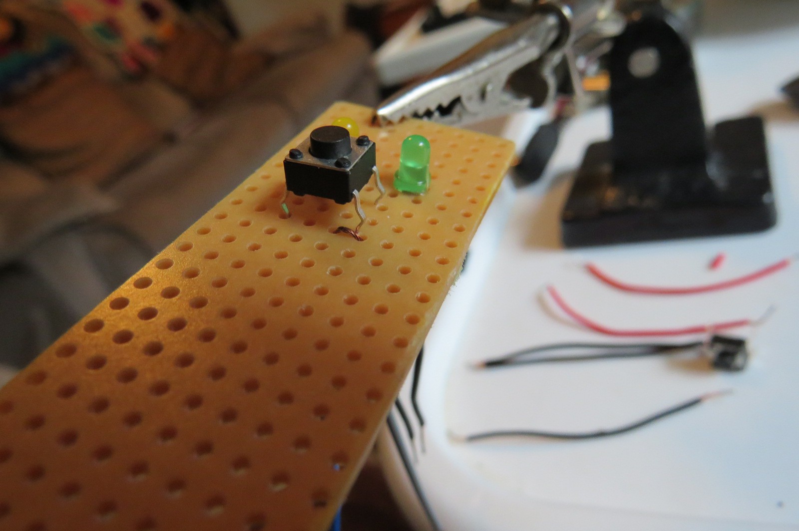
Then, solder on the buttons. I found the easiest way was to loop the wire into the perf board (through a hole under the button), and then out the hole where the leg of the button would be coming out. This way, they are both coming out the same direction and it made it a lot easier to solder.
You can see the loops here:
Make sure that you put the loops on opposite sides of the button, so that they are not connected normally.
Then place your button on top of the loops....
... and squeeze it down.
Solder wires to the two ends of the button on the opposite side of the perf board:
I also put a little solder on the unused legs, just for additional physical support.
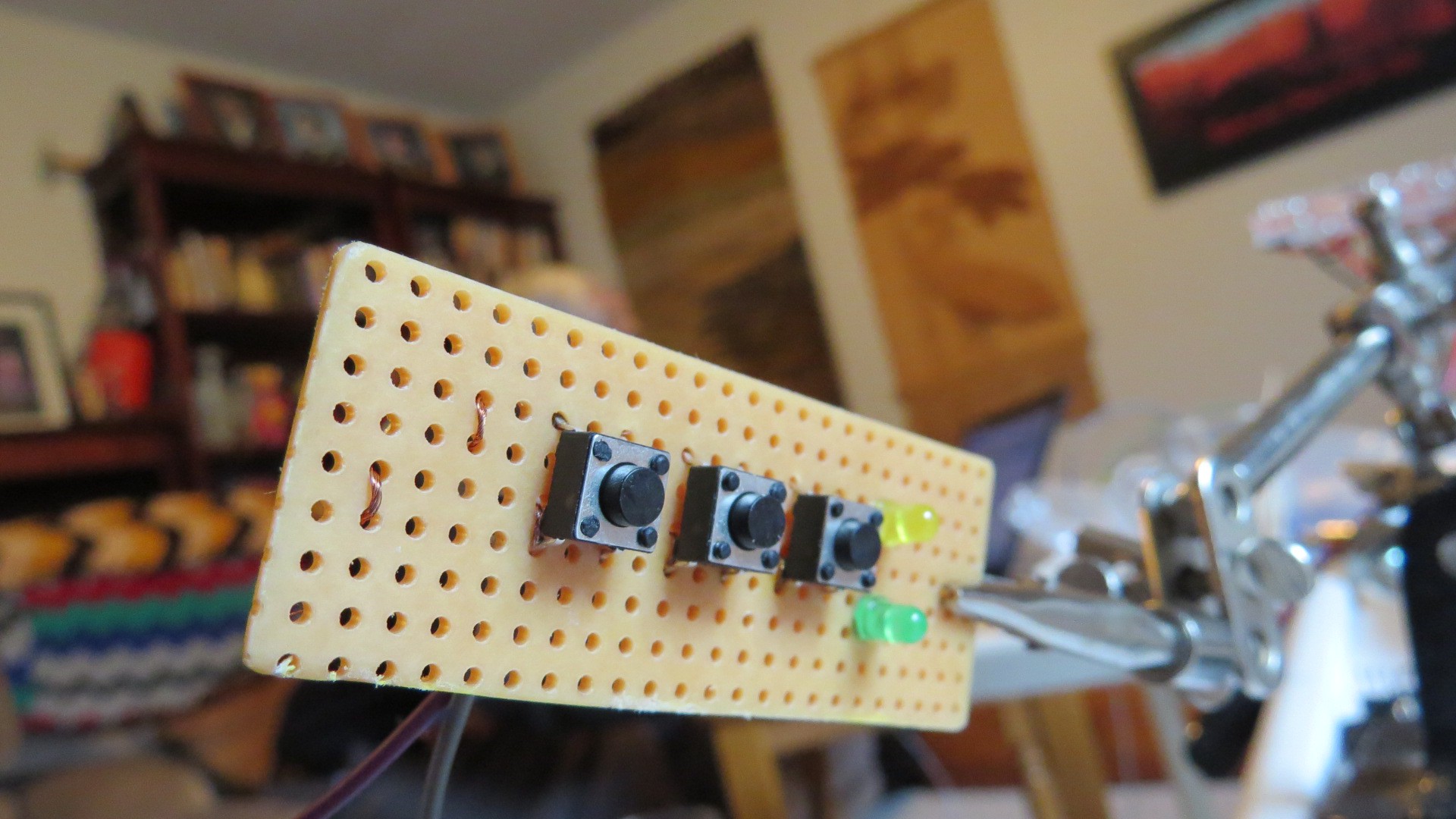
Complete this for the rest of the buttons:
-
6Step 6
Step 6: Solder the project board
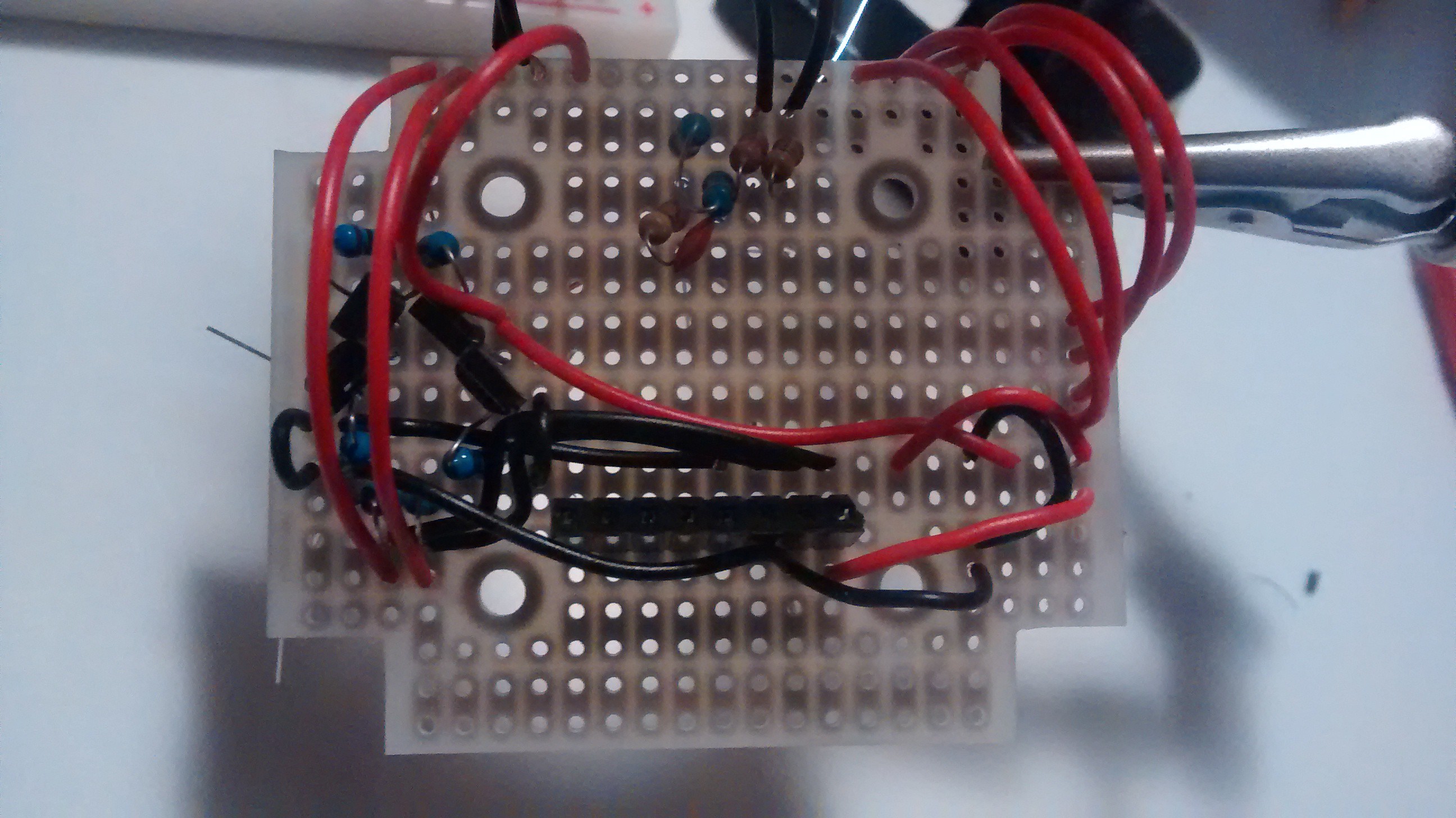
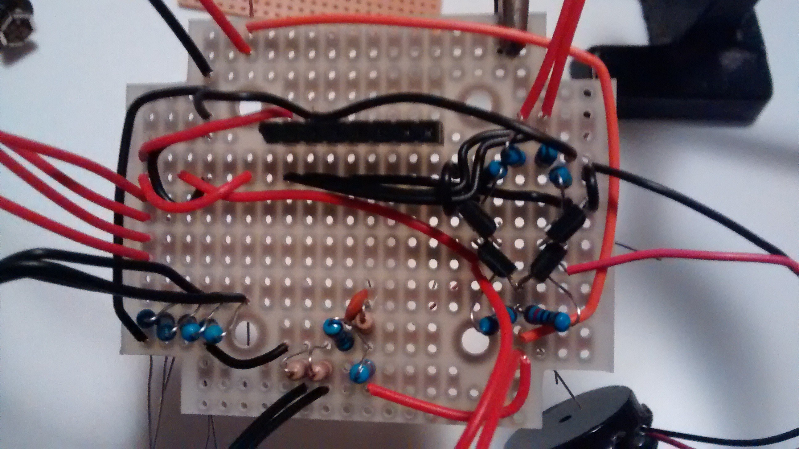
It takes a fair amount of time to solder the board. I started with placing all the passive components and wires on the board, and then turning it over and soldering all of those components.
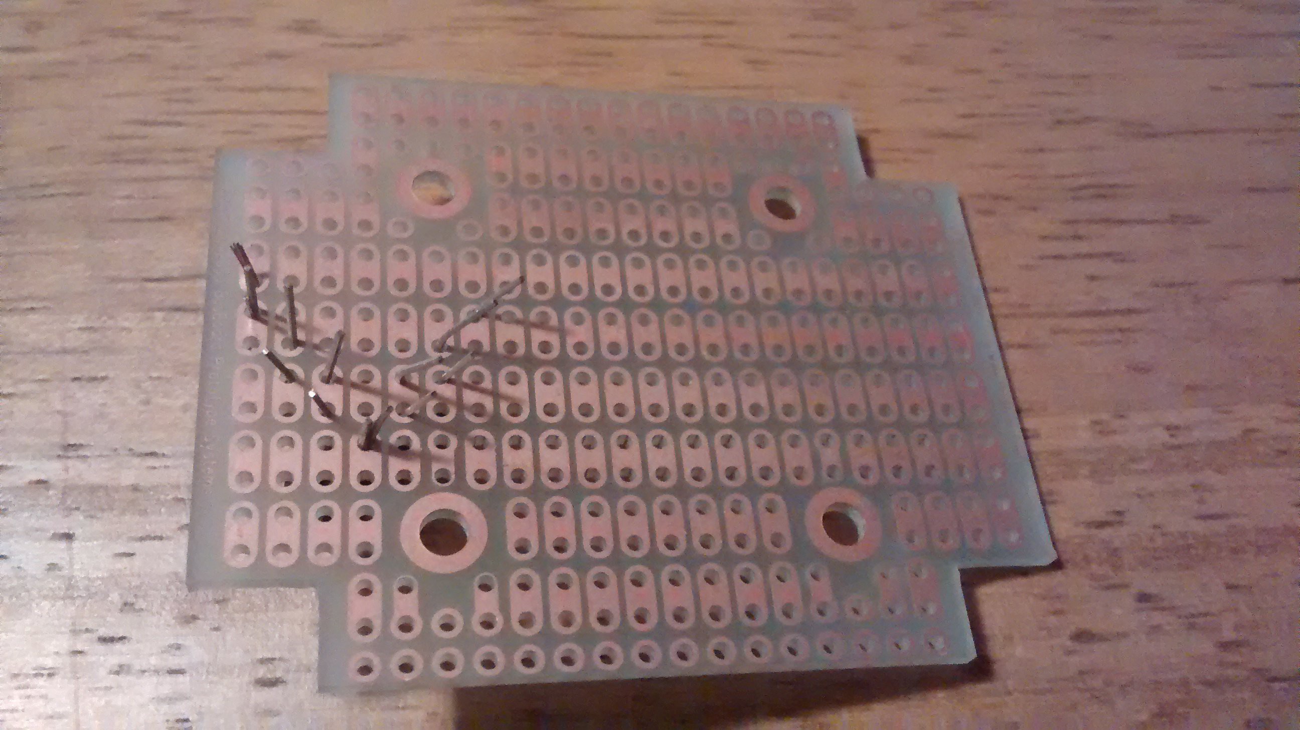
The board that comes with the box is a one-sided board. I placed all the components on the side that does NOT have the plating, and then did the soldering on the side that does have the plating. In many cases, there are multiple things that go into the same hole (e.g. resistor and a wire) so make sure you get both in there before soldering it up.
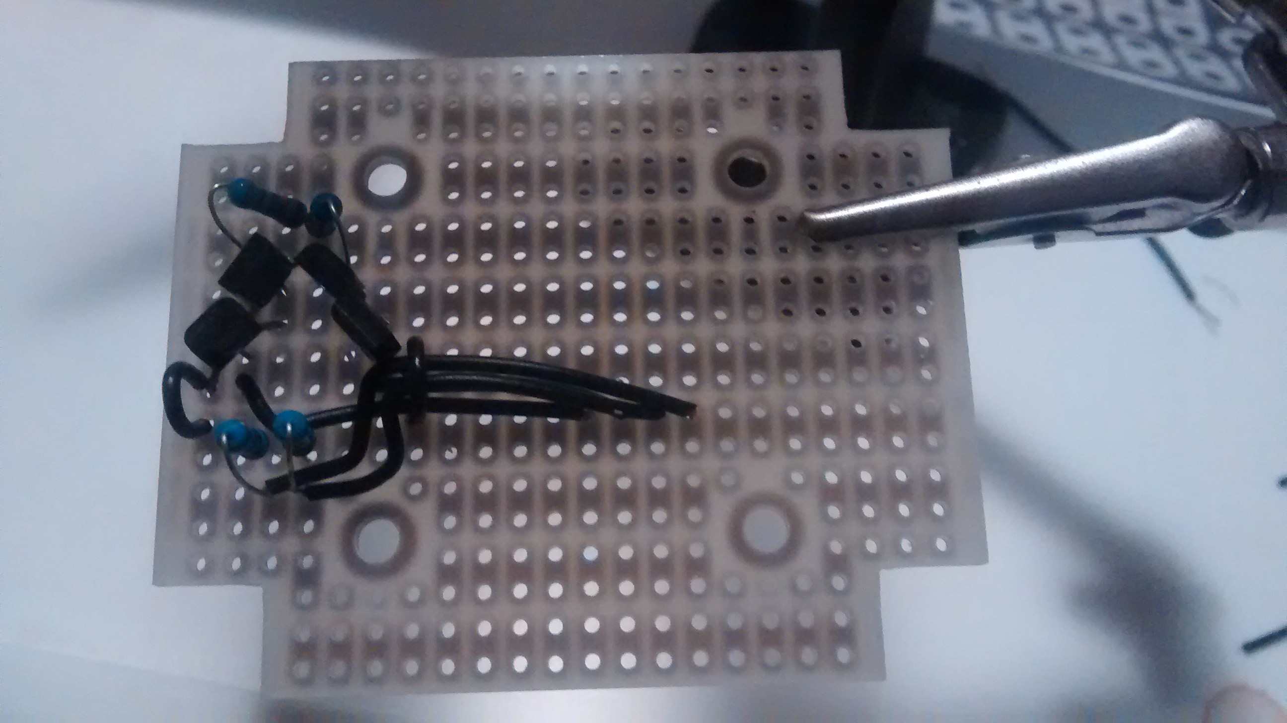
First, do the transistors, resistors for the power circuit and wires that run to them from the Trinket Pro pins. I used little loops of wire to run the ground link from the source of the N-Channel MOSFETs, and then the wires that would come from out from under the Trinket Pro through them. Always be conscious that you need to put the Trinket Pro overtop of these wires.
![]()
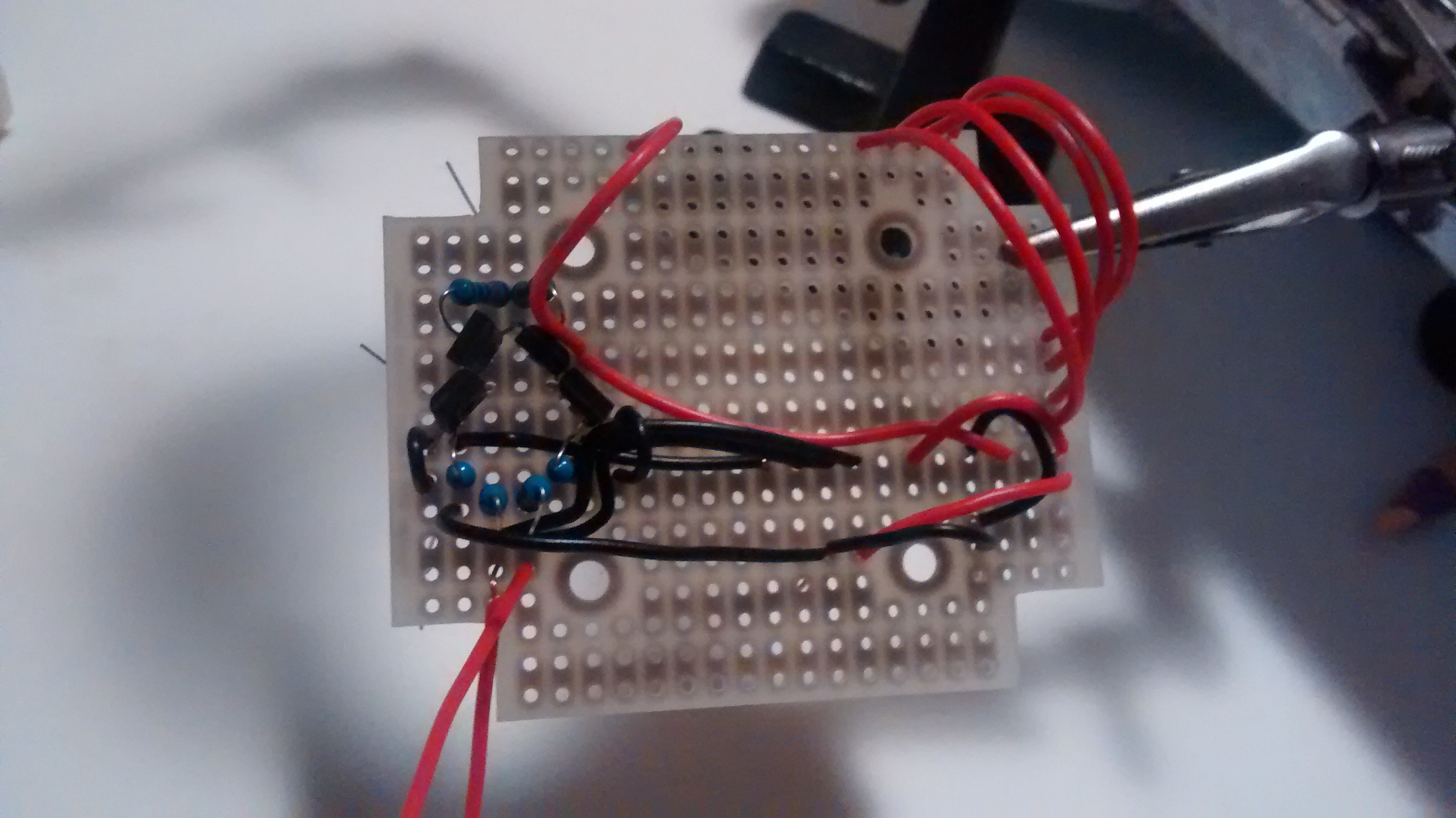
The add more of the wires. I had red and black hook up wire, so the red was power and the black was ground and logic wires.
![]()
![]()
(In the above, ignore the four red wires in the top right... they are to connect the four buttons on the perf board)
Periodically (when done a section), I would flip it over and solder those components):
![]()
Add the power monitor circuit components (top middle):
![]()
Add the other components and wires:
![]()
Note, still a few wires to add in the above (e.g. from SDA and SCL to the Trinket Pro) but I found those easiest to do after. Each to their own in ordering tho.
Note, do not complete soldering on this board, as you still need to connect the perf board wires to the project board.
-
7Step 7
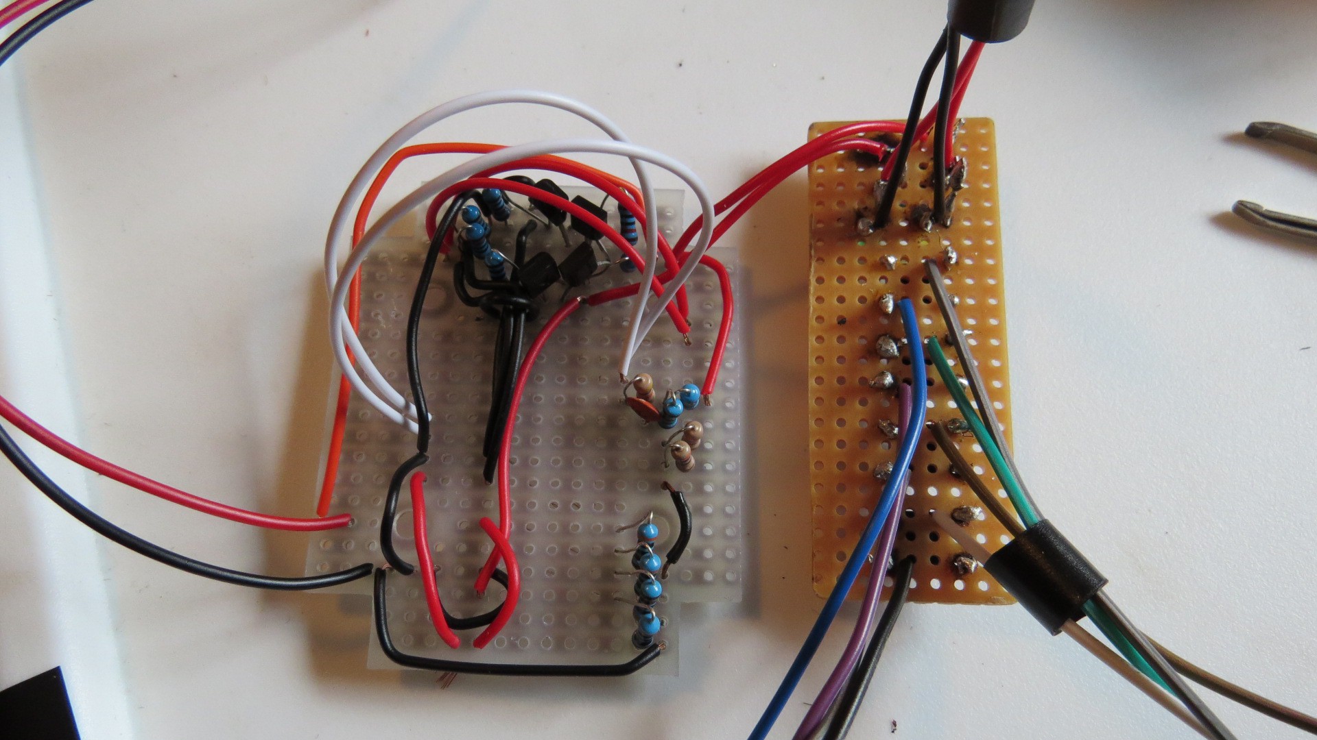
Step 7: solder the connection between the perf board and the project board
Connect the two boards by soldering the wires from the perf board to the right spot on the project board. You should not have soldered these connections yet.
Start with one button (here, the power button):
And then complete the rest of the connections:
Note: I had temporarily removed the header for the the GY-521 while doing this soldering.
-
8Step 8
Step 8: Add the Trinket Pro
Insert the Trinket Pro over top of the wires in the center of the board.
And then flip it over and solder the remaining pins.
-
9Step 9
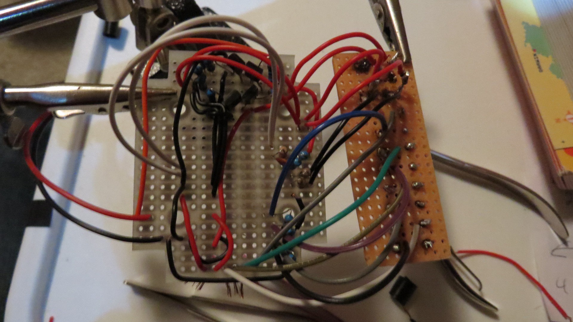
Step 9: Insert accelerometer and finalize soldering
Finalize any soldering (e.g. ground rails) and insert the GY-521 accelerometer into the header.
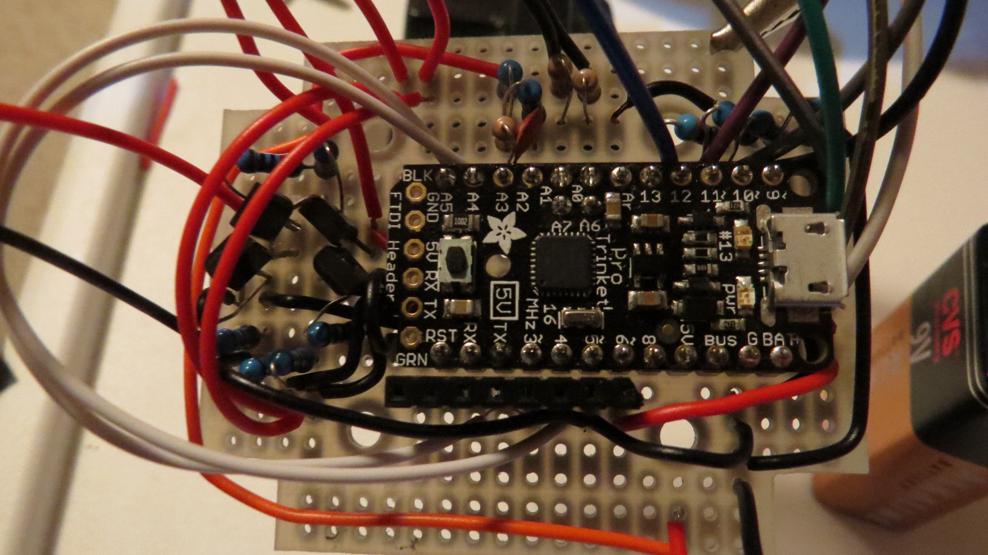
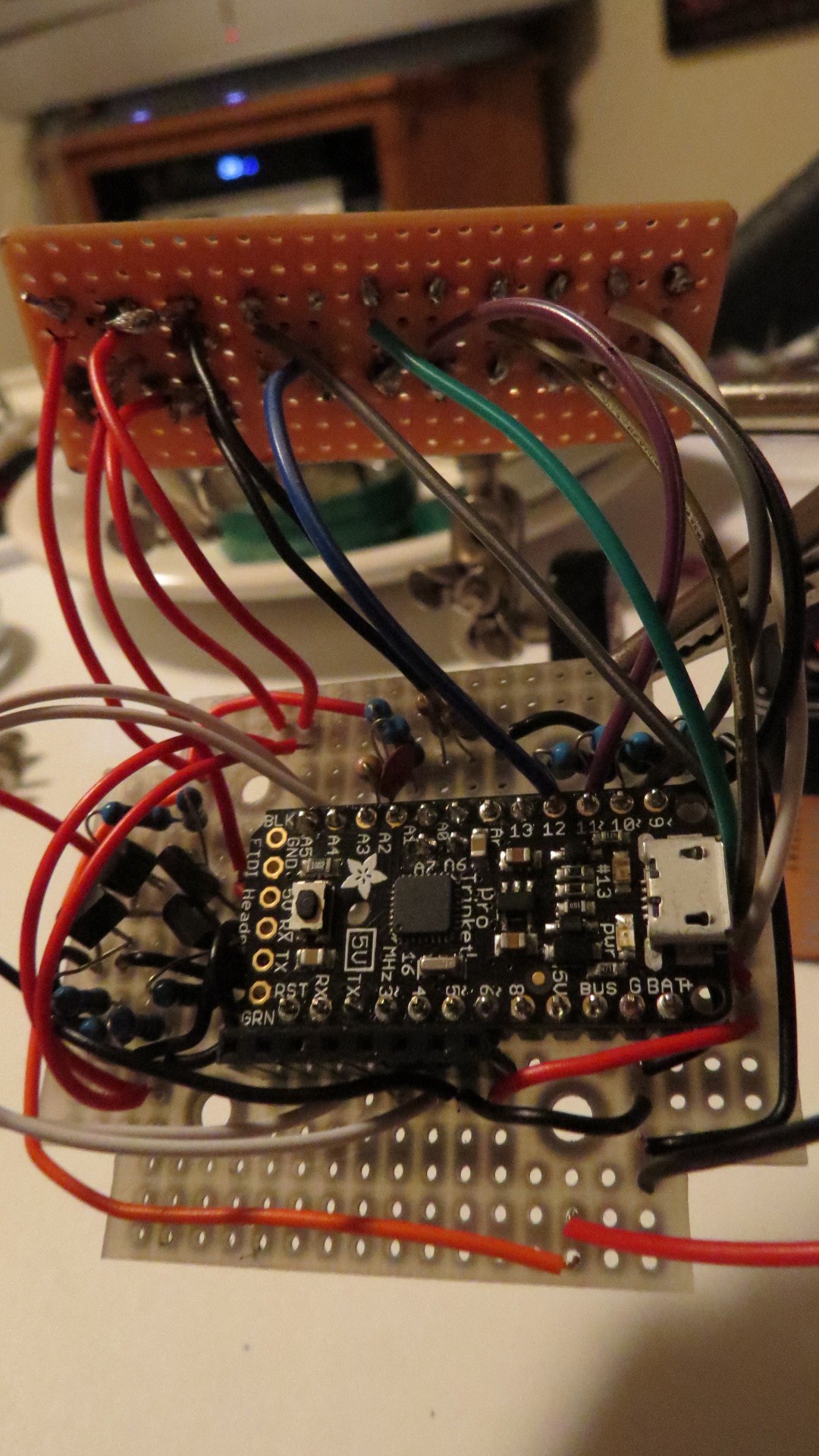
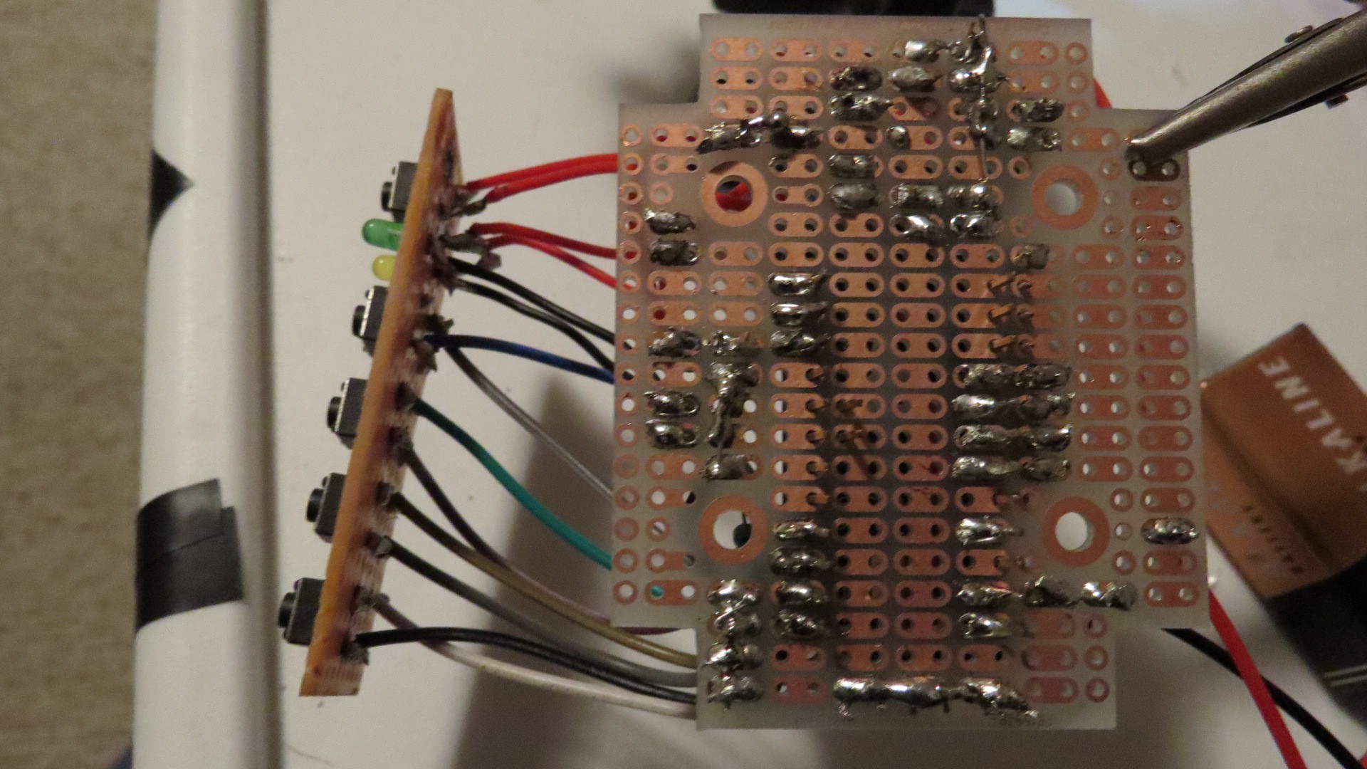
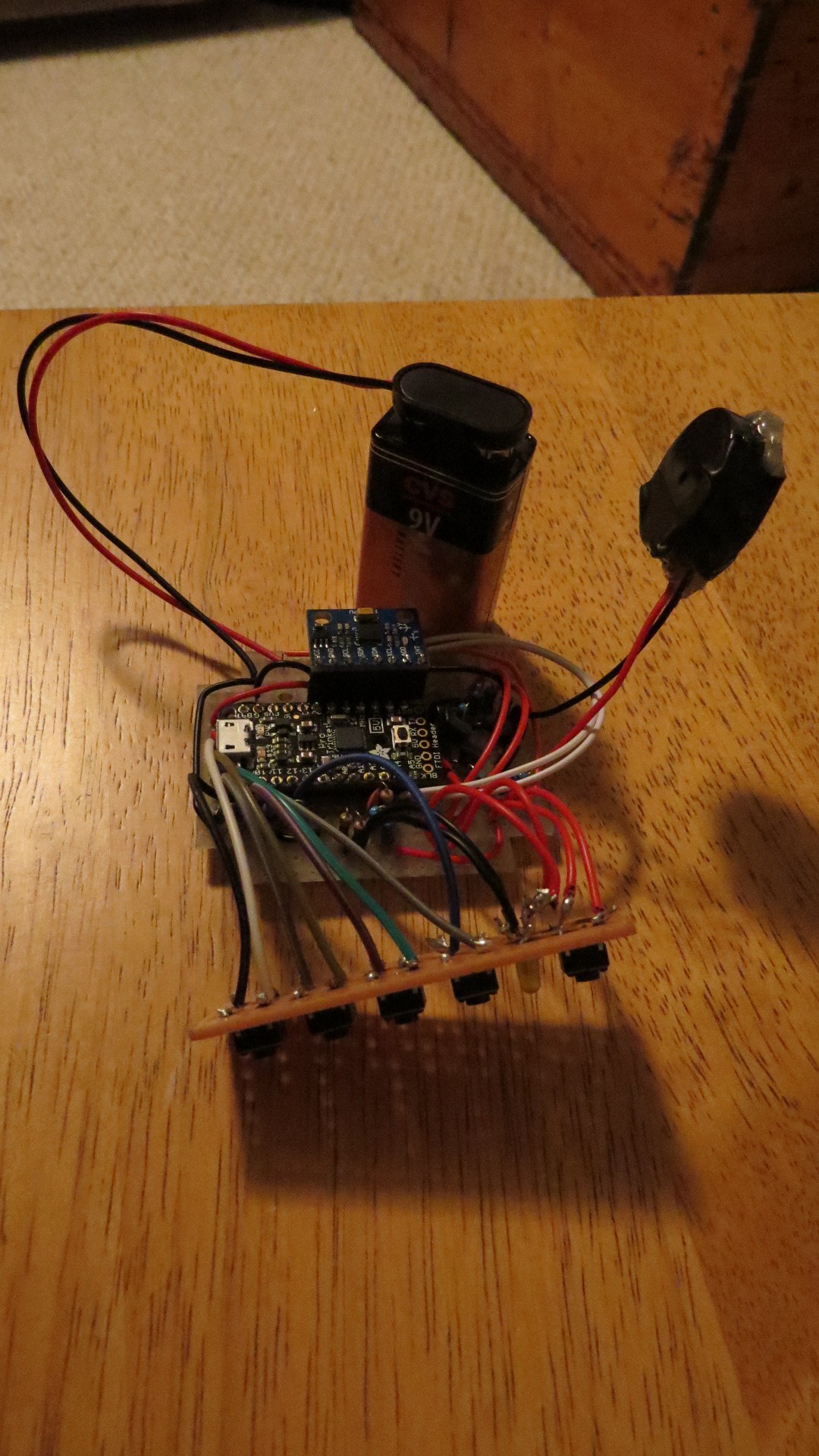
Completed connections. Whew!
-
10Step 10
Step 10: Program the board
Really, you could do this first, but you will likely need to do it here anyway to do some modifications.
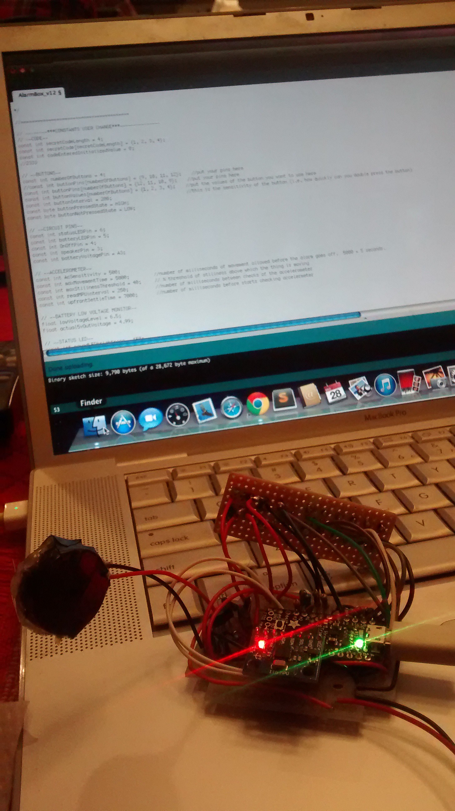
The Trinket Pro requires you to take a few steps to get code to upload. Read more at MakerSelf (my personal blog) as to how to do this.
![]()
Download the ino code, or copy from here:
---------- more ----------
/* alarmbox.ino Implements a movement alarm box with a security code using buttons as the way to input the code. The project includes utilizes an accelerometer to track movement, a set of buttons to input the security code and power the project on, and Trinket Pro as the brains (although other implementations of an ATMega328 could be substituted). The number of buttons, the number of digits in the secret code, and the numerical value of each button (for the code), the sensitivity of the movement testing, and the timeframes for various components of the user experience can all be defined independently. The box has a power circuit where pressing and holding the power button turns the project on, but then does not work to turn the box off. The box can only be turned off by the software. There is no need for resetting the code entered periodically as the code entered is simply made up of the last X number of digits that had been entered (X depends on the length of the secret code). User interface [indicate changable elements]: (1) Device is normally off. Press and hold power button for 3-5 seconds to turn decice on; wait for the Status LED [green LED] to turn on. (2) After powering up, Status LED will blink for [10] seconds. During this time the user must enter the [secret code]. This is to ensure against turning on accidentally as well as to ensure that user remembers what the code is before the device gets armed. If the user does not successfully enter the secret code during this time, the device turns itself off. (3) After successfully entering the code, the Status LED will turn solid on. This indicates that the device is giving the user time to put the device stationary, in this sketch [20] seconds. (4) The Status LED turns off, indicating that the device is now armed and listening to the accelerometer. If there is movement, the Status LED blinks slightly to indicate movement. (5) If there is movement for more than [5] seconds and above [threshhold], the alarm goes off and turns the Status LED solid on. The alarm stays on until the user enters the secret code. (6) Once the device is on, if the user enters the secret code after or during the settling time, the Status LED will blink once long, then three short, and then then the device will turn itself off without turning the alarm on. (5) If the battery is low voltage, set as below [6.5] volts, then when the Status LED is turned on in step (1) or in (5) or (6), the Battery Low Voltage LED [yellow LED] will turn on solid on. Created December 2014 by MakerSelf (makerself.com) Please use, modify and be merry! */ //======================================== // --------***CONSTANTS USER CHANGE***--------------- // --SECRET CODE-- const int secretCodeLength = 7; //secret code can be any length. Suggest 4-7 digits. const int secretCode[secretCodeLength] = {1, 2, 3, 4, 3, 2, 1}; //secret code is hard coded const int codeEnteredInitializedValue = 0; //suggest something that is NOT in the possible values from the buttons pressed // --BUTTONS-- const int numberOfButtons = 4; //reflects number of buttons in the circuit const int buttonPins[numberOfButtons] = {9, 10, 11, 12}; //put your pins here, depending on which pins your have wired to in the circuit. const int buttonValues[numberOfButtons] = {1, 2, 3, 4}; //put the values of the button you want to use here const int buttonInterval = 200; //this is the sensitivity of the button (i.e. how quickly can you double press the button) const byte buttonPressedState = HIGH; //can either tie pins to ground (in this sketch) or to +5V rail const byte buttonNotPressedState = LOW; // --CIRCUIT PINS-- //put your pins here for your circuit const int statusLEDPin = 6; //must be PWM pin const int batteryLEDPin = 5; //either PWM or just HIGH/LOW out const int OnOffPin = 4; //either PWM or just HIGH/LOW out const int speakerPin = 3; //suggest PWM pin, depending on your speaker/alarm const int batteryVoltagePin = A3; //must be an analog in pin // --ACCELEROMETER-- const int AcSensitivity = 1400; //high enough so that little bumps dont trigger it, but movement does. Will need to experiment. const int maxMovementTime = 5000; //number of milliseconds of movement allowed before the alarm goes off. 5000 = 5 seconds. const int maxStillnessThreshold = 20; // % threshold of stillness above which the thing is moving const int readMPUinterval = 250; //number of milliseconds between checks of the accelerometer const int upfrontSettleTime = 20000; //number of milliseconds before starts checking accelermeter // --BATTERY LOW VOLTAGE MONITOR-- float lowVoltageLevel = 6.5; //Warning level. Trinket Pro indicates that it needs 5.5 V (although apparently can handle a bit less), so this give a bit of head room before it becomes a problem, and is approximately the knee of the battery discharge curve for 9V ones I have found float actual5vOutVoltage = 4.99; //use a volt meter to test what the AREF is to get what the logic level is. This should nominally be 5v. Just helps the accuracy of the battery monitor, but not necessary: can just assign as 5.00. // --STATUS LED-- const int movedLEDbrightness = 150; //whatever you want. Set here for about 50% brightness, which is visable but not annoying. // --STARTUP PHASE ASKING FOR CODE TO BE ENTERED-- const int startingTime = 10000; //time up front where the user needs to enter the code to cause it arm const int startingMillisBlinkInterval = 200; //whatever you want // ---------***CONSTANTS THAT THE USER DOES NOT CHANGE***--------- const int MPU=0x68; // I2C address of the MPU-6050 const int maxMovementTimeArrayDifference = maxMovementTime / readMPUinterval; // number of array entries necessary for their to be movement const int movedRecordLength = maxMovementTimeArrayDifference * 2; //need to keep more than just the maxMovementTime otherwise if the first or the last in the array is 'not moved' then sketch will consider it to be not moved. boolean movedRecord[movedRecordLength]; //the array of each check to see if it moved. Recent ones gets added, and old ones get shifted out. //------------**** VARIABLES ****--------------------- int codeEntered[secretCodeLength]; //array of the buttons pressed so far. This gets initilized. byte buttonStates[numberOfButtons]; //array of buttonStates, for debouncing. This gets initilized. unsigned long previousButtonMillis[numberOfButtons]; //timer for button presses. Array of last time the button was pressed, for debouncing. This gets initilized. byte speakerState; //gets set before speaker is called int AcX,AcY,AcZ; //accelerometer values int OldAcX,OldAcY,OldAcZ = 0; //old accelerometer values from last time it was checked boolean moved = false; //to track if it is moved boolean isStolen = false; //to track if the device has been stolen (exceeds the max movement time and threshold) unsigned long previousMPUmillis = 0; //timer for checking the accelerometer unsigned long endOfSetupMillis; //to track when the setup has ended (user has successfully put in the code to arm the device) unsigned long previousSerialMillis; //for debugging or printing to the serial. Gets initialized to zero when begin Serial Communication. Unecessary for sketch to work. // -------LIBRARIES---------------- #include<Wire.h> //for communicating to the accelerometer // ================================================================================== // --------MAIN PROGRAM--------------- void setup() { //--TURN ON CIRCUIT VIA SOFTWARE-- //turn the Circuit on via transistor pinMode(OnOffPin, OUTPUT); // initialize digital OnOffPin as an output. digitalWrite(OnOffPin, HIGH); // turn the OnOffPin HIGH and thus the power circuit transistor on by making the voltage HIGH pinMode(statusLEDPin, OUTPUT); // initialize the statusLED as an output digitalWrite(statusLEDPin, HIGH); // turn the statusLED on to show that the power is flowing to the TrinketPro without the continued press of the power button. //INITALIZE THINGS //intialize speaker pinMode(speakerPin, OUTPUT); //intialize the speakerPin as an output //initialize codeEntered and Buttons initializeCodeEntered(); //makes the code entered be all zeros (or whatever value you define) initializeButtons(); //make the buttons ready to be pressed //initialize MPU accelerometer beginMPUcommunications(); //start communicating with the accelerometer initializeMovedRecord(); //set the moved record as all 'not moved' //initialize battery monitor pinMode(batteryVoltagePin, INPUT); //initilize the analog in pin for reviewing the battry voltage pinMode(batteryLEDPin, OUTPUT); //Battery LED pin digitalWrite(batteryLEDPin, LOW); //assume that the battery is fine unless below the threshold. //to communicate and debug Serial.begin(9600); //for debugging. Unecessary for sketch to work. previousSerialMillis = 0; //for debugging. Unecessary for sketch to work. //--ACTUAL ACTION-- //check battery and put on LED if low boolean isVoltageTooLow = voltageCheck(); if (isVoltageTooLow == true) { digitalWrite(batteryLEDPin, HIGH); //battery LED is solid on, even if the status LED is flashing } //end if //blink to indicate that code is to be entered. If not entered, shut off. unsigned long currentMillis = millis(); unsigned long previousStartingMillis = currentMillis; //need these as they get tested once before being set again in the while loop int startingLEDstate = HIGH; digitalWrite(statusLEDPin, startingLEDstate); boolean isMatchedSetup = doesCodeEnteredMatchSecretCode(); //this is probably unnecessary (could just set isMatchedSetup == false) as at this point user will have had to be milisecond quick to have entered the code, but might as well leave it in and it only gets run once. while (isMatchedSetup == false && currentMillis < startingTime) { //stays in this while loop until the code is matched or starting time elapses with no code pressed. Nothing else happens except this. //blink the LED if ((currentMillis - previousStartingMillis) > startingMillisBlinkInterval) { //blink to LED on the blink interval set above startingLEDstate = !startingLEDstate; digitalWrite(statusLEDPin, startingLEDstate); previousStartingMillis = currentMillis; } //end if to blink LED //read buttons and see if the code entered via the button matches the secret code yet readButtonsAndShiftEnteredCode(); isMatchedSetup = doesCodeEnteredMatchSecretCode(); //reset the timer currentMillis = millis(); } //end the while for waiting for the code to be entered successfully or starting time to pass //code was entered successfully if (isMatchedSetup == true) { digitalWrite(statusLEDPin, HIGH); //when the code has been entered successfully, set the Status pin to solid (indicating waiting time) and... initializeCodeEntered(); //...reinitilize the code entered so far back to zeros } else //isMatched == false, so it was the currentMillis that ended the while and code was not entered successfully in the startingTime { digitalWrite(OnOffPin, LOW); //shut off the circuit } //exit from setup and go to loop endOfSetupMillis = millis(); //need this so the settling time can start properly } //end setup void loop() { //--------REAL WORLD--------------- // Get new timer for each round of the loop unsigned long currentMillis = millis(); // indicate that you are within the settle time by turning the LED high, if not, put the pin low if (currentMillis < (endOfSetupMillis + upfrontSettleTime)) { digitalWrite(statusLEDPin, HIGH); } else { digitalWrite(statusLEDPin, LOW); digitalWrite(batteryLEDPin, LOW); //if battery LED pin is on, it will turn off. If battery LED pin was off, this makes no difference. } // start reading the MPU on a regular basis (if outside of the upfront settle time) and then check to see if device has been stolen after each reading if (((currentMillis - previousMPUmillis) > readMPUinterval) && (isStolen == false) && (currentMillis > (endOfSetupMillis + upfrontSettleTime))){ // read the MPU and process the data checkPositionChangeAndShiftRecord(); printMovedRecord(); //for debugging. Not necessary for sketch to work. isStolen = checkIfStolen(); previousMPUmillis = currentMillis; //reset timer } //end if //read the buttons and check to see if it matches readButtonsAndShiftEnteredCode(); //read the buttons and add them to the entered code if a button has been pressed boolean isMatched = doesCodeEnteredMatchSecretCode(); //check to see if the code matches //take action if stolen if (isStolen == true) { digitalWrite(statusLEDPin, HIGH); if (isMatched == true) { //if the entered code matches the secret code, turn the LED off, the speaker off, and the device off 2 seconds later (could shut it off at the same time, but I wanted to make it obvious they were separate) digitalWrite(statusLEDPin, LOW); speakerState = false; speakerPlayBuzzer(speakerState); //this speaker play can be changed to different function depending on what type of buzzer you are using (e.g. does it need a tone, etc.) //turn off device delay(2000); digitalWrite(OnOffPin, LOW); } // if isMatched else { //code does not yet match speakerState = true; speakerPlayBuzzer(speakerState); //see comment above about the speaker play function } } else { //end if stolen now look at when it has not been stolen if (isMatched == true) { //if the entered code matches the secret code (and it was not stolen), turn on the LED to flash it, then turn the device off. //check battery and put on LED if low boolean isFinalVoltageTooLow = voltageCheck(); //check the voltage again and put on the LED. Could be different than during the setup, as some time may have passed. byte voltageLEDfinalStatus = LOW; if (isFinalVoltageTooLow == true) { voltageLEDfinalStatus = HIGH; } //end if //flash the status pin before turning off. This is quick and dirty flash based on delays. I could have made this based on some timer, but felt it was unnecessary as the code is just heading to shutting the device down. digitalWrite(statusLEDPin, HIGH); //flash the status LED digitalWrite(batteryLEDPin, voltageLEDfinalStatus); //flash the battery LED along with the status LED delay(1000); digitalWrite(statusLEDPin, LOW); digitalWrite(batteryLEDPin, LOW); delay(100); digitalWrite(statusLEDPin, HIGH); digitalWrite(batteryLEDPin, voltageLEDfinalStatus); delay(200); digitalWrite(statusLEDPin, LOW); digitalWrite(batteryLEDPin, LOW); delay(100); digitalWrite(statusLEDPin, HIGH); digitalWrite(batteryLEDPin, voltageLEDfinalStatus); delay(200); digitalWrite(statusLEDPin, LOW); digitalWrite(batteryLEDPin, LOW); delay(100); digitalWrite(statusLEDPin, HIGH); digitalWrite(batteryLEDPin, voltageLEDfinalStatus); delay(200); digitalWrite(statusLEDPin, LOW); digitalWrite(batteryLEDPin, LOW); //turn off device delay(2000); digitalWrite(OnOffPin, LOW); } //if matched }//else //--------SERIAL COMMUNICATIONS------------- //This section is for debugging, and is unnecessary for the sketch to run. //print out the entered code and if matched. if ((millis() - previousSerialMillis) > 1000) { //only print every so often, eg. every 1 second for (int x = 0; x < secretCodeLength; x++){ //print the secretCode Serial.print(codeEntered[x]); } //end for Serial.println(); //make new line previousSerialMillis = millis(); //record when you did the last print } //end serial printing if //------------------------------------------- } //end loop // ================================================================================== // --------FUNCTIONS--------------- //--Button and code functions-- void readButtonsAndShiftEnteredCode() { //PURPOSE: read the buttons and then call shiftCodeEntered if a button has been are pressed for (int x = 0; x < numberOfButtons; x++) { //step through all buttons unsigned long currentMillis = millis(); if ((currentMillis - previousButtonMillis[x]) > buttonInterval) { //check to see if enough time has passed since last press int newButtonState = digitalRead(buttonPins[x]); //if enough time has passed, read the buttons if (newButtonState == buttonPressedState && buttonStates[x] == buttonNotPressedState) { //only add to the code entered if it has from NotPressed to Pressed (i.e pressing and holding does not give more than one press) shiftCodeEntered(buttonValues[x]); //if button was pressed, add its value to code array previousButtonMillis[x] = currentMillis; //reset button time } //end button state check if buttonStates[x] = newButtonState; //update the button state } //end millis if } //end of number of buttons for loop } //end readButtons void shiftCodeEntered(int buttonValue) { //PURPOSE: shifts the code one to the left, and then adds the value of the most recent pressed button on the right for (int x = 0; x < secretCodeLength; x++) { //step through the code codeEntered[x] = codeEntered[x+1]; //for each code spot, shift it to the left. the first digit gets lost. if (x == (secretCodeLength-1)) { //if the last spot, add the new digit from the button press codeEntered[x] = buttonValue; } //if }//for } //end shiftCodeEntered void initializeCodeEntered() { //PURPOSE: initializes all spots in the code entered at the initization value, which is typically zero. This is so you dont get an error and should be a different set of characters than is on the buttons (i.e. if the buttons are of value 1 - 4, make initilization 0) or ensure that this code will not be the secret code (i.e. can have any code except for all zeros) //make each of the codes equal to the initial value it is to be assigned (typically 0) for (int x = 0; x < secretCodeLength; x++) { //step through the code entered codeEntered[x] = codeEnteredInitializedValue; //for each digit, get it to the initilized value (typically zero) }// end for } //end resetCodeEntered void initializeButtons() { //PURPOSE: initilizes all the buttons as inputs, as not pressed, and waiting for a press for (int x = 0; x < numberOfButtons; x++) { //step through the buttons pinMode(buttonPins[x], INPUT); //for each button, make that buttons pin an input buttonStates[x] = buttonNotPressedState; //for each button, intialize each button as not pressed previousButtonMillis[x] = 0; //for each button, intialize when it was last pressed at zero (so can record future presses correctly) } } //end initializeButtons boolean doesCodeEnteredMatchSecretCode() { //PURPOSE: check each digit of the entered code and the secret code against each other to see if they match boolean isMatched = true; //assume the code is matched, and then make it not matched as soon as there is one different for (int x = 0; x < secretCodeLength; x++) { //step through the code entered if (isMatched == false || codeEntered[x] != secretCode[x]) { //if the code entered digit at that code spot does not equal the secret code digit at the code spot, or do not match in any previous checks, then make it false isMatched = false; //for each digit, get it to the initilized value (typically zero) } //end if } // end for return isMatched; //return this to main program, to tell it if the code was matched or not } //end doesCodeEnteredMatchSecretCode // --Speaker Functions-- void speakerPlayPiezo(boolean isSpeakerOn) { //PURPOSE: Turn the speaker on or off. For use with a simple piezo speaker. if (isSpeakerOn == true) { tone(speakerPin, 200, 1000); //chose your tone, or have several tones. } //end if isSpeakerOn } //end speakerPlayPiezo void speakerPlayMallory(boolean isSpeakerOn) { //PURPOSE: Turn the speaker on or off. For use with a mallory speaker (this may need adjustment) int frequency = ((1 / 3400)*1000000)/2; //chose based on the frequency of the speaker for (long i = 0; i < 3400 * 3; i++ ) { digitalWrite(speakerPin, HIGH); delayMicroseconds(frequency); digitalWrite(speakerPin, LOW); delayMicroseconds(frequency); } //end if } //end SpeakerPlayMallory void speakerPlayBuzzer(boolean isSpeakerOn) { //PURPOSE: Turn the speaker on or off. For use with a simple ON/OFF buzzer. if (isSpeakerOn == true) { digitalWrite(speakerPin, HIGH); } else //isSpeakerOn == false { digitalWrite(speakerPin, LOW); } //end if isSpeakerOn } //end speakerPlayBuzzer //--Battery Voltage Monitor functions-- boolean voltageCheck() { //PURPOSE: check the voltage on the battery and see if it is less than the threshold, returning a boolean of if it is too low or not // read the input on the voltage int sensorValue = analogRead(batteryVoltagePin); // Convert the analog reading (which goes from 0 - 1023) to a voltage (0 - 5V): float voltage = sensorValue * (actual5vOutVoltage/1023.0) * 2; //in circuit, use a voltage divider to bring the 9v below the 5v for the analog in pin. Use two equal resistors for the voltage divider so multiply by two here to get the actual voltage. //Serial //only for debugging purposes. Unnecessary for sketch to run. Serial.print(" SV: "); Serial.print(sensorValue); Serial.print(" Voltage: "); Serial.print(voltage); // check to see if the voltage is below the threshold boolean isVoltageTooLow = false; //assume it is not too low, unless the comparison results in it being too low if (voltage < lowVoltageLevel) { isVoltageTooLow = true; } return isVoltageTooLow; } //--Accelerometer functions-- void initializeMovedRecord() { //PURPOSE: set the moved record at all false to begin with. for (int x = 0; x < movedRecordLength; x++) { movedRecord[x] = false; } //end for } //end initializeMovedRecord void beginMPUcommunications() { //PURPOSE: begin communications with MPU accelerometer. Done once. Wire.begin(); Wire.beginTransmission(MPU); Wire.write(0x6B); // PWR_MGMT_1 register Wire.write(0); // set to zero (wakes up the MPU-6050) Wire.endTransmission(true); } //end beginMPUcommunications void readMPUrawvalues() { //PURPOSE: read the raw values from the accelerometer. Wire.beginTransmission(MPU); Wire.write(0x3B); // starting with register 0x3B (ACCEL_XOUT_H) Wire.endTransmission(false); Wire.requestFrom(MPU,14,true); // request a total of 14 registers AcX=Wire.read()<<8|Wire.read(); // 0x3B (ACCEL_XOUT_H) & 0x3C (ACCEL_XOUT_L) AcY=Wire.read()<<8|Wire.read(); // 0x3D (ACCEL_YOUT_H) & 0x3E (ACCEL_YOUT_L) AcZ=Wire.read()<<8|Wire.read(); // 0x3F (ACCEL_ZOUT_H) & 0x40 (ACCEL_ZOUT_L) } //end readMPUrawvalues void checkPositionChangeAndShiftRecord() { //PURPOSE: read the raw values from the accelerometer, check against the old values. If there is movement above the sensitivity level, add 'true' to the movement record, if not, add 'false' to the movement record readMPUrawvalues(); //Check to see if it has moved and add to the move record if (abs(OldAcX - AcX) > AcSensitivity) { moved = true; } if (abs(OldAcY - AcY) > AcSensitivity) { moved = true; } if (abs(OldAcY - AcY) > AcSensitivity) { moved = true; } shiftMovedRecord(moved); //add the moved value (either true or false) to the moved record //turn on Status if moved if (moved == true) { analogWrite(statusLEDPin, movedLEDbrightness); } //reset the values for next check OldAcX = AcX; OldAcY = AcY; OldAcZ = AcZ; moved = false; } //end checkPositionChangeAndShiftRecord void shiftMovedRecord(boolean movedValue) { //PURPOSE: shifts the movedRecord one to the left, and then adds the value of the most recent moved record the right for (int x = 0; x < movedRecordLength; x++) { //step through the movedRecord movedRecord[x] = movedRecord[x+1]; //for each record spot, shift it to the left. the first record gets lost. if (x == (movedRecordLength-1)) { //if the last spot, add the new record from the most recent record movedRecord [x] = movedValue; } //end if }//end for } //end shiftMovedRecord boolean checkIfStolen() { //PURPOSE: step through the moved record and see if the record meets the circumstances deemed to mean the at the device is stolen boolean stolenStatus = false; //assume it has not been stolen until it has been proven stolen //---------------First test: is there movement more than 5 seconds apart int firstMoved = movedRecordLength -1; //initalize as the far end of where it will start int lastMoved = 0; //initalize as the far end of where it will start boolean firstMovedSet = false; boolean lastMovedSet = false; boolean movedEnoughTime = false; for (int x = 0; x < movedRecordLength; x++) { // get first moved, starting from 0. Note this will cycle through the whole record, even if it finds first moved early. Okay but slightly inefficient. if (movedRecord[x] == true && firstMovedSet == false) { firstMoved = x; firstMovedSet = true; } //end if } //end for for (int x = (movedRecordLength - 1); x >= 0; x--) { // get last moved, starting from the end of the moved record. Note this will cycle through the whole record, even if it finds last moved early. Okay but slightly inefficient. if (movedRecord[x] == true && lastMovedSet == false) { lastMoved = x; lastMovedSet = true; } //end if } //end for if ((lastMoved - firstMoved) > maxMovementTimeArrayDifference){ movedEnoughTime = true; } //-------------end First test ----------------------------------------- //---------------Second test: if there is movement over 5 seconds, is it more than the threshold if (movedEnoughTime == true){ int trueCounter = 0; for (int x = firstMoved; x <= lastMoved; x++) { //step through the movedRecord between the first moved and the last moved positions if (movedRecord[x] == true) { trueCounter++; //count the number of trues in the section of movedRecord } //end if } //end for int movementPercent = map(trueCounter, 0, lastMoved - firstMoved + 1, 0, 100); //map the trueCounter amount out of the number of records being checked, to a 0 to 100 percentage. This allows the use of interger math. if (movementPercent > maxStillnessThreshold) { stolenStatus = true; } //end greater than maxStillnessThreshold else { stolenStatus = false; } //end less than maxStillnessThreshold } //end-----------------Second test --------- if movement over difference in array return stolenStatus; } //end checkIfStolen //--------------------SERIAL COMMUNICATIONS -------------------------------------- //only for debugging. Unnecessary for the sketch to run. void printMovedRecord() { for (int x = 0; x < movedRecordLength; x++) { Serial.print(movedRecord[x]); } //end for Serial.println(); } //end initializeMovedRecord
TrinketPro Movement Alarm for Bag Theft Prevention
A portable, battery powered device that sounds an alarm when your bag is moved. Once armed, can only be turned off by your secret code.







Discussions
Become a Hackaday.io Member
Create an account to leave a comment. Already have an account? Log In.