-
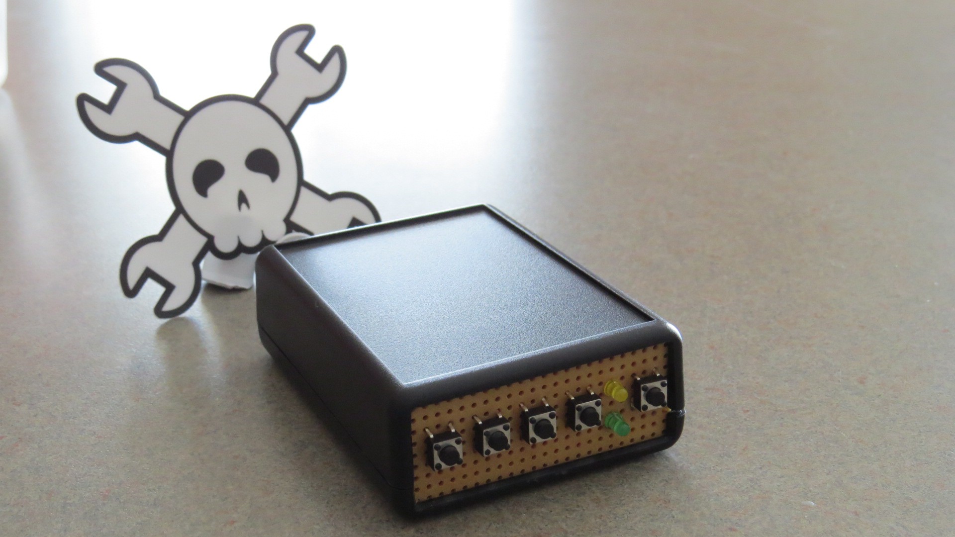
Project complete!
01/03/2015 at 22:36 • 0 commentsWell, the project is now complete and fully functioning!
![]()
You can see a video of it in action:
I have also uploaded a number of things to be helpful if anyone wants to replicate this:
1) Detailed instructions! (see the instructions on this project page)
2) Schematic and circuit diagrams. See Step 3 of the instructions.
3) The code, which is well commented. See Step 10 of the instructions.
-
Project in project box
01/01/2015 at 20:34 • 0 commentsIn the previous log, I had finished soldering the PCB, and tested it outside of the project box.
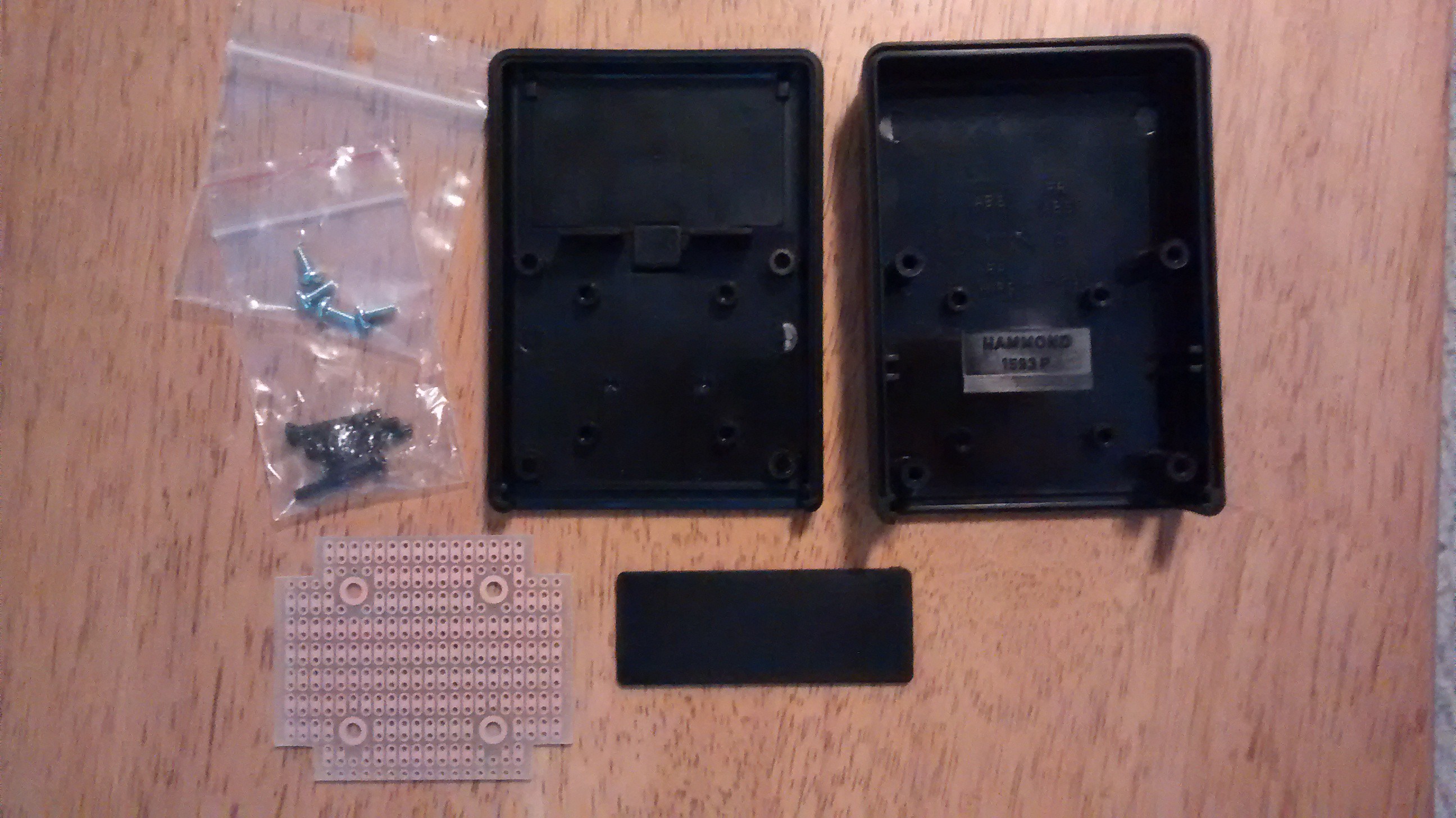
I then took the PCB, the perf board with the buttons, and put it into a project box I had ordered specifically for this project. This was the project box, which included a custom PCB to fit into the box.
![]()
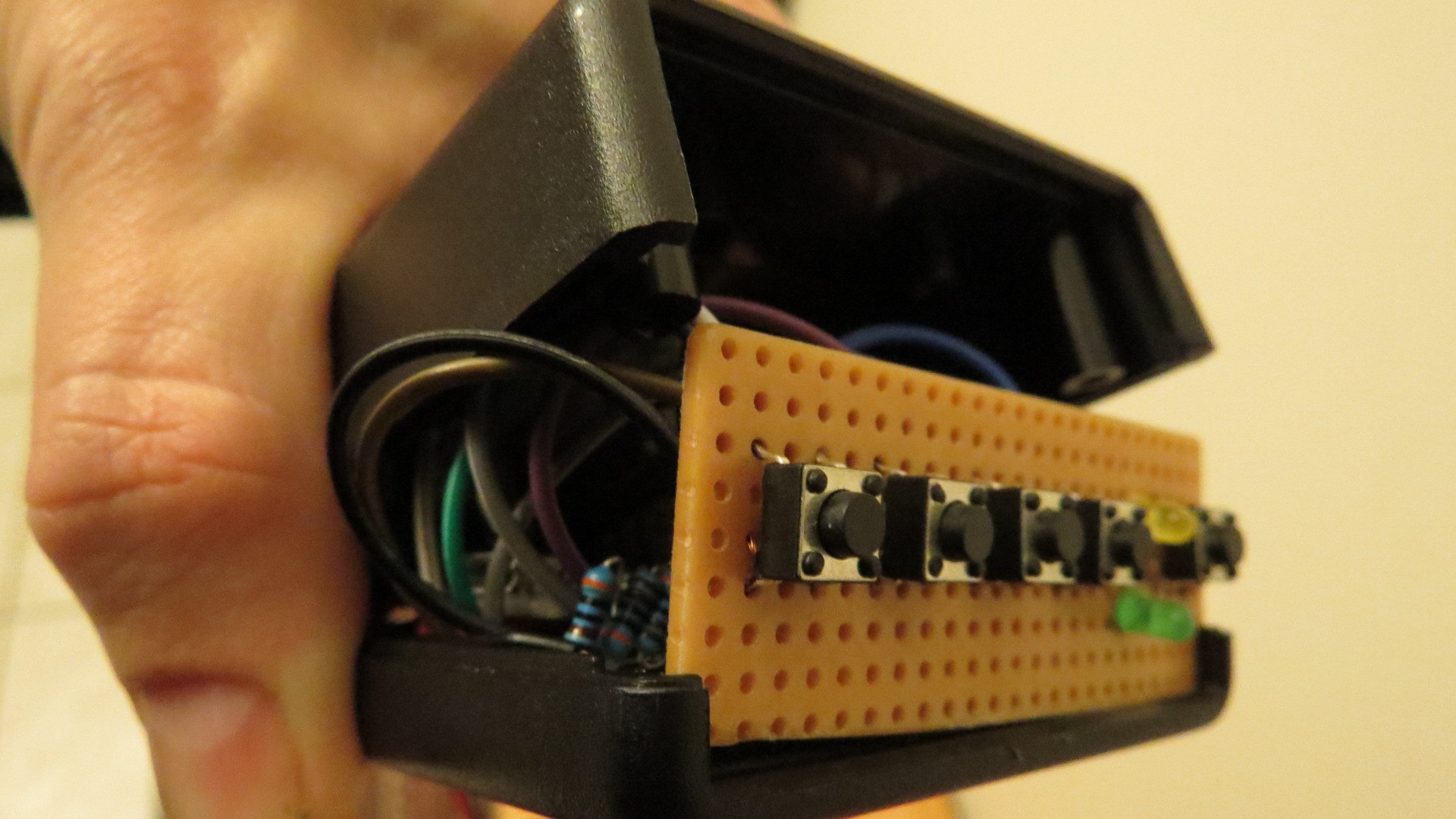
I then had to squish the wiring, the alarm, and the PCB into the project box, which proved to be a little bit of a challenge. I managed to get it, but really had to work to fit it in, and bend the wires in the right way.
![]()
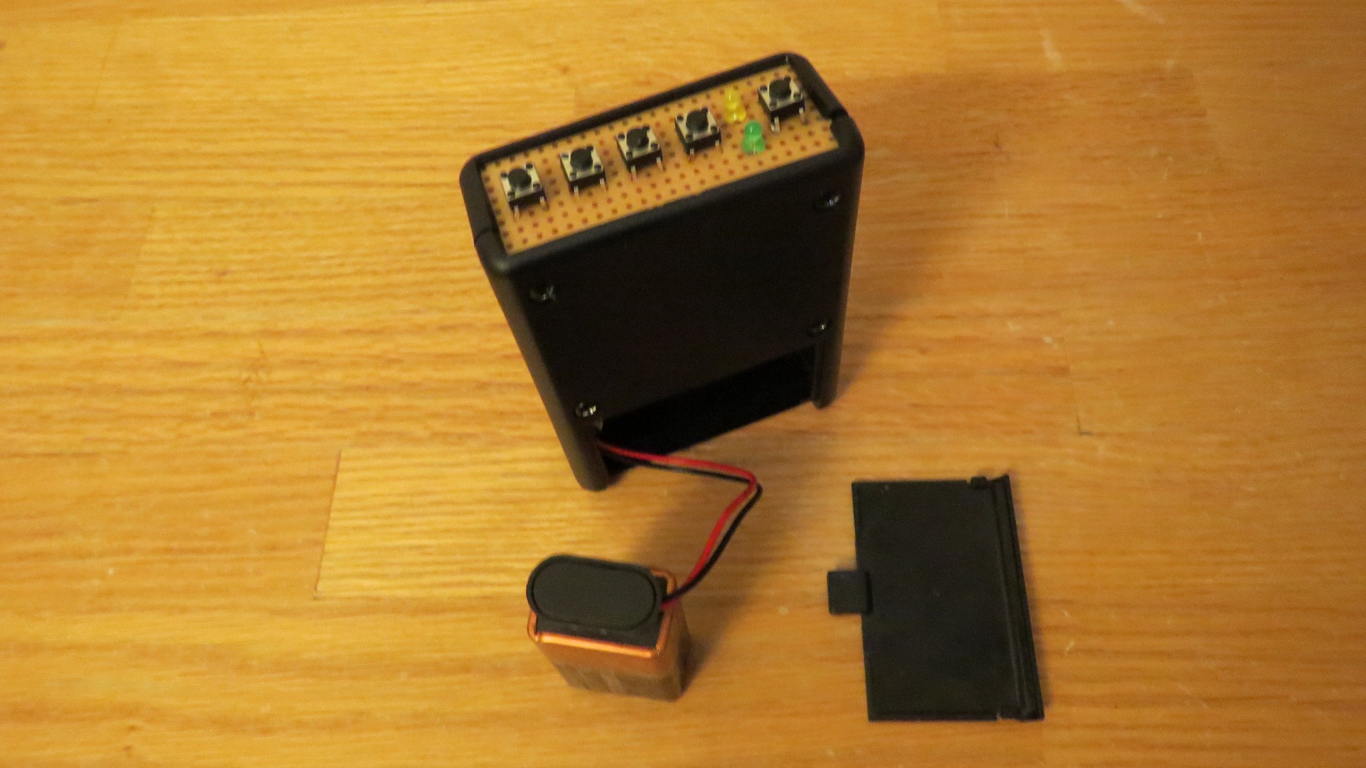
Then I screwed it shut and tested it out! Works like a charm.
The completed project:
![]()
-
Soldering complete!
12/27/2014 at 08:20 • 1 commentI thought for a little while it wouldn't all fit, but I managed to squeeze the entire prototype onto a small little PCB that will fit into a project box that I have, with the buttons and LEDs on a bit of perf board that will replace one of the ends of the box.
It took me sometime to figure out how to lay it all out (I took a picture of the blank PCB, printed it out, and drew on it), and then it took a solid day and a half to actually do the soldering (thankful for holidays right now!). There were a few moments were I thought I had screwed it up, and it is a bit of a leap of faith because you need to wait until it is all done until you can really test it.
BUT, it is finished, and it works!
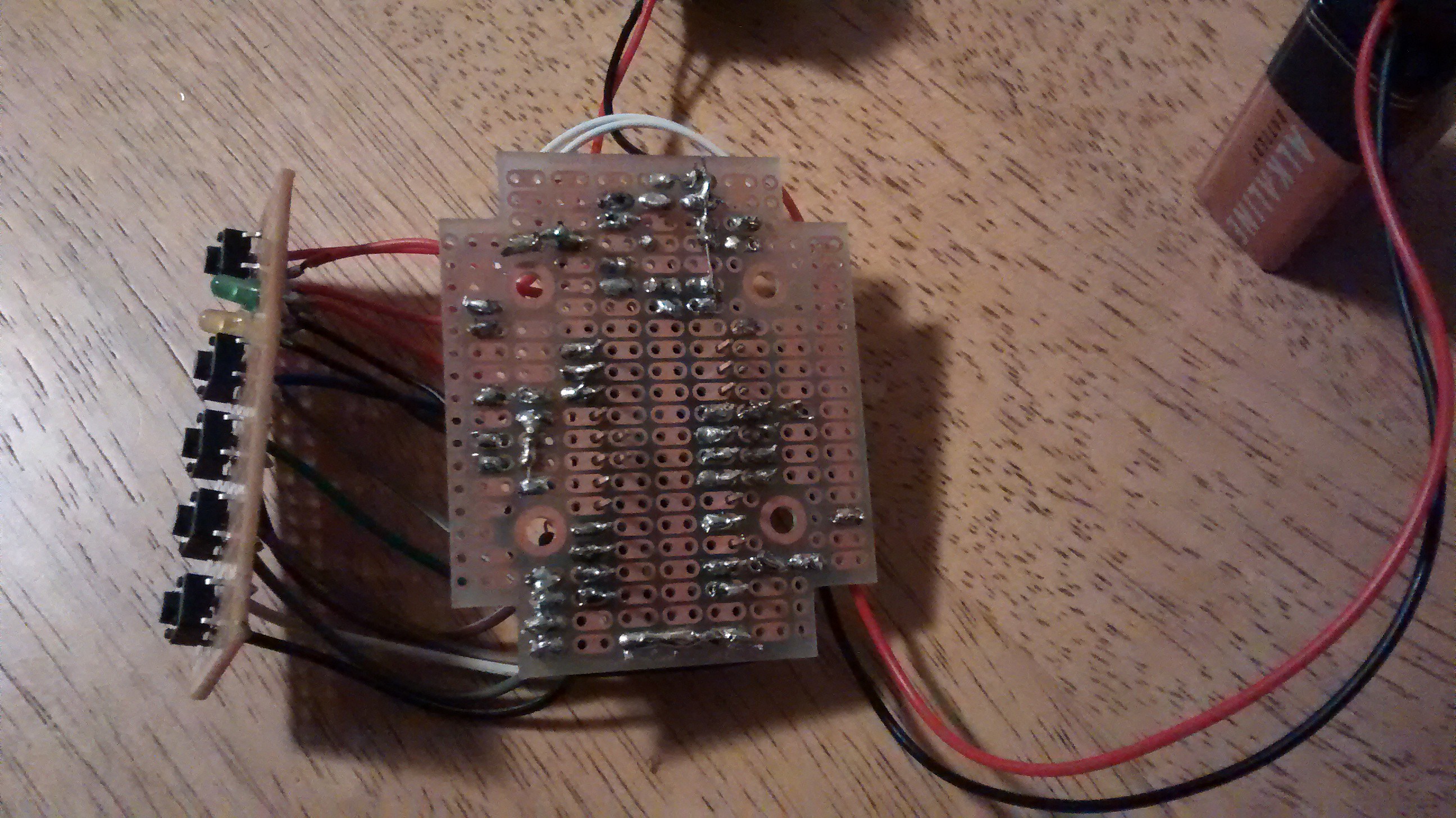
You can see most of it in the pictures. There are a number of wires running underneath the TrinketPro, which was the last thing to be added.
![]()
![]()
![]()
And a video of it in action:
-
Prototype Complete!
12/26/2014 at 10:05 • 0 commentsOkay, so a lot has happened since my last project update:
1) Integrated the TrinketPro into the project. I needed to change my sketch a bit, but the big issue was that with the TrinketPro the power circuit no longer works. I just couldn't find a resistance level that would keep the processor off normally, but allow the transistor to keep it on.
2) Redesigned the power circuit. Some web poking and a post on the Arduino forums helped solve this issue. Solution was to utilize a p-channel MOSFET along with an n-channel MOSFET, using this as the inspiration:
3) Added a battery power monitor circuit and sketch. I use a voltage divider (two equal resistors) to bring the voltage below 5v, and then use an analog in pin to measure the voltage (x2 to get the actual voltage). Crude, but functional, and really it is just a low battery warning.
4) Added some UX elements to the sketch (e.g. when it is armed, can enter the code to shut it off without triggering the alarm).
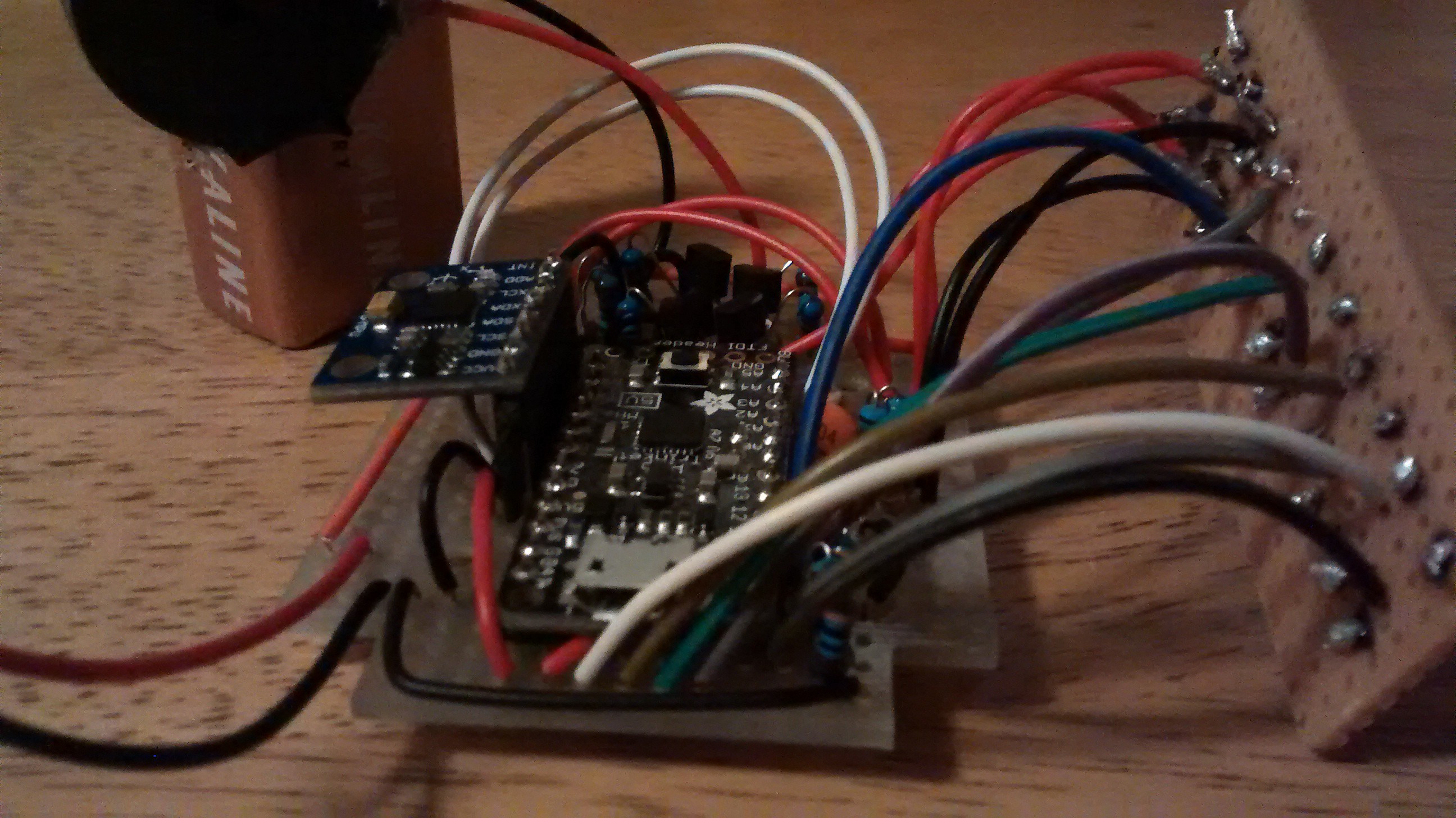
The completed circuit is below, as is a video of it in action.
From the top:
![]()
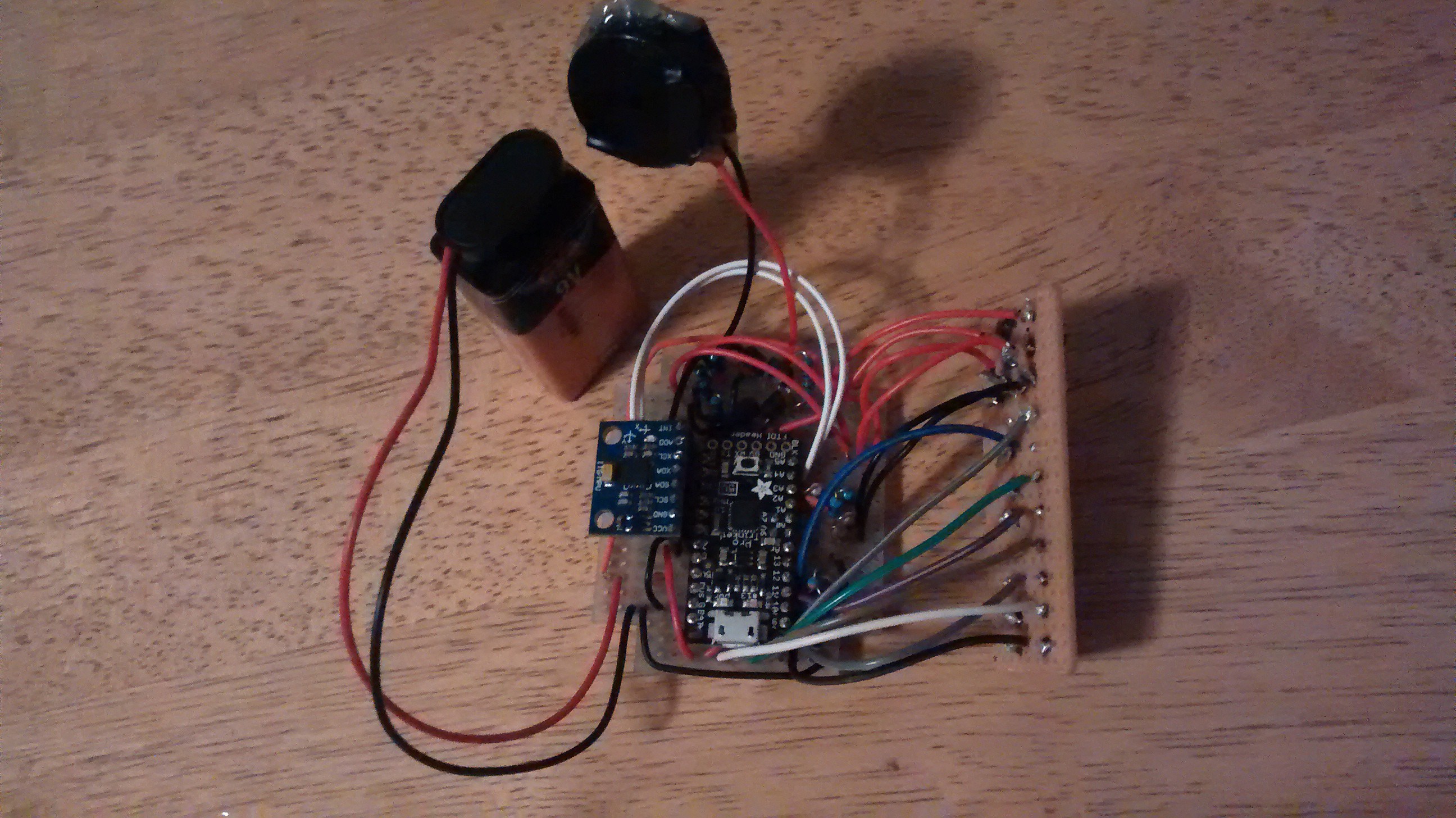
And a close up:
![]()
A video of it in action:
-
TrinketPro arrived!
12/22/2014 at 01:44 • 0 commentsMy Trinket Pro arrived!!
Looks pretty cool, especially with that black Hackaday mask on it!
![TrinketPro... a little small, but packs an Uno punch!]()
I ordered one from the hackaday store, and it came without headers soldered on, so I soldered them right on, including a short two pin header on the A6 and A7 pins (the location of these two pins is inside from the edge, and as a result when in a breadboard these two pins will be the same as A0 and A1. In a perf board, these could be separate).
The first step was to see if I could program it. This proved to be a bit of a challenge.
The introduction pdf was extremely helpful, as was the overview from Adafruit.
There were three challenges:
1) Adding the Trinket Pro as an eligible board. I needed to download the boardfile from Adafruit, and extracted to a folder that I put in the my Arduino folder (end result: arduino/hardware/Trinket Pro/boards.txt).
2) Utilizing the USBtinyISP driver to install via the USB drive (instead of the FTDI header). I tried downloading the driver from Adafruit and installing it on my Windows machine, but it would not install. The install window would just flash briefly and then disappear, as if there was nothing to install. I tried several times. Luckily, I also have an old MacBook Pro which already has USBtinyISP installed. So, instead of using my Windows machine, I needed to transfer files to my MacBook and then I could program the TrinketPro. It also labeled the serial ports differently than on my Windows machine: instead of "COM6″ etc., it used "/dev/cu.Bluetooth-PDA-Sync".
3) Timing the programming. The TrinketPro requires that you press the reset button to put it into the bootloader mode, and then you have window of time to upload a new program before is goes into running the current program on the board. I found that if I pressed the reset button on the TrinketPro and then pressed the upload button on the IDE, the compile would take too long and the bootloader would exit before the uploading began. I needed to press the upload button in the IDE on the computer, wait a second or two, and then press the reset button on the TrinketPro to get into bootloader mode. If I did that, the sketch would upload successfully!
-
Integrated the accelerometer
12/21/2014 at 08:28 • 0 commentsI finally got the accelerometer delivered, and I wanted to integrate it into the circuit and the code.
I first experimented with the accelerometer as a separate entity, and then once I had developed a working code for the accelerometer, integrated it into the main alarm box code.
The big challenge was not reading the accelerometer raw values or putting in a sensitivity to determine if it has moved, but for telling how LONG there has been movement, and only if there is movement for say 5 seconds does it trigger the alarm… if it is moving for longer than 5 seconds then it has been stolen! The difficult part is that there may be moments in there where there is no movement, e.g. for a half second it may stop but then start moving again, and I don't want that to 'reset' the movement time counter.
Here is the approach:
- I would store the "moved" value in an array, shifting the new one in each time I take a reading. Since I have the sensor reading at 1/4 of a second right now, to store the previous 5 seconds of "moved" would take 20 elements. Each time I read a sensor value, I drop the oldest one, and add the newest one to the array.
- I would then look to see if there is a more than 5 second period between two moments of movement (i.e. it has been potentially been moving for more than 5 seconds). As if I only stored 5 seconds of data and the alarm only goes off if there is more than 5 seconds of movement, it would only go off if the very first and the very last elements in the array were recorded as moved, I needed to store MORE than the movement time. I decided to store the previous 10 seconds of data, and look at any more than 5 second period in that.
- Then, I would loop through each element of the array and count how many are "moved" and how many are "not moved" between those two moments of movement, to see if it exceeds a threshold amount (say I allow 20% not movement before).
This way, there would be two tests:
- Does the time between the oldest "moved" and the newest "moved" exceed 5 seconds? (i.e. it has potentially been moving for more that 5 seconds)
- If so, does "moved" exceed the threshold value for that time period? (i.e. it has actually been moving)
I can thus exclude the two events I want to exclude:
- Two blips more than 5 seconds apart, but with little movement in between (below the threshold).
- Movement (even 100% of the time) of say 4 seconds, and then stop.
I would only include it as "stolen" if:
- There are two blips of movement more than 5 second apart (with some maximum time period between moments of movement)
- AND there has been movement above the threshold in between those two blips (e.g. 80% of the time it has been moving)
-
Button based security code
12/16/2014 at 04:55 • 0 commentsThe last update was talking about the steps to build the circuit, and this is about using the circuit. I needed to program it so that when you pressed the arm button, it would turn on. A event (in the final product, movement) would trigger the alarm, and then the code would turn it off.
I built this up over the course of a few days, starting with a simple version using delays, and then building out the button based security code utilizing non-blocking code. I was very happy with the result, and stripped out some the unnecessary pieces for the power circuit component, and posted it to the Ardunio.cc forum (see the post) as a standalone button based security code sketch. Hoping to get some feedback, and also wanted to share in case someone wanted to do something similar.
I have posted the code as it stand so far (includes the power on, and the button based code) below, but also wanted to share a video of it operational so far:
The code (the comments make it a little difficult to follow, sorry!)
/* alarmbox.ino Implements a security code using buttons as the way to input the code. Number of buttons, the number of digits in the secret code, and the numerical value of each button (for the code) can be defined independently. This code can be used to take any action when the secret code is entered correctly. In this example, the on board LED is on while the secret code has not been correctly entered, and then is turned off when the secret code is entered correctly. The sketch also prints the code that has been entered so far to the serial monitor, along with if it has been matched (only when matched). There is no need for resetting the code entered periodically as the code entered is simply made up of the last X number of digits that had been entered (X depends on the length of the secret code). The circuit: * If no LED on the board that is attached to pin 13, attach an LED from pin 13 to ground * For each button you choose to have for inputs into the entered code (in this sketch there are four buttons, but you can change that): -- Use a normally open button (i.e. only on when you press it, then it pops up) -- Connect from one side of the button to ground through a resistor (A decent size, in this example 1k resistors were used but you can use 10k or similar larger value.) -- Connect from the other side of the button to a digital I/O pin on the arduino board. (in this sketch, button 1 was connected to pin 8, button 2 to pin 9, button 3 to pin 10, button 4 to pin 11, but you can change that as long as you change it in the sketch (noted where you do that). Created December 2014 by MakerSelf (makerself.wordpress.com) Please use, modify and be merry! */ //======================================== // --------CONSTANTS--------------- const int secretCodeLength = 7; const int secretCode[secretCodeLength] = {1, 2, 3, 4, 3, 2, 1}; const int codeEnteredInitializedValue = 0; const int numberOfButtons = 4; const int buttonPins[numberOfButtons] = {8, 9, 10, 11}; //put your pins here const int buttonValues[numberOfButtons] = {1, 2, 3, 4}; //put the values of the button you want to use here const int buttonInterval = 300; //this is the sensitivity of the button (i.e. how quickly can you double press the button) const byte buttonPressedState = LOW; const byte buttonNotPressedState = HIGH; const int OnOffPin = 7; const int speakerPin = 6; //------------ VARIABLES--------------------- int codeEntered[secretCodeLength]; //this gets initilized byte buttonStates[numberOfButtons]; //this gets initilized unsigned long previousButtonMillis[numberOfButtons]; //this gets initilized byte speakerState; unsigned long previousSerialMillis; //for debugging or printing to the serial if that is the objective. Gets initialized to zero when begin Serial Communication. // ================================================================================== // --------MAIN PROGRAM--------------- void setup() { //turn the Circuit on via transistor pinMode(OnOffPin, OUTPUT); // initialize digital OnOffPin as an output. digitalWrite(OnOffPin, HIGH); // turn the OnOffPin HIGH and thus the transistor gate open by making the voltage HIGH pinMode(13, OUTPUT); // use digital pin 13 to show when the OnOffPin is high. for debugging, to be removed in final version. digitalWrite(13, HIGH); // use digital pin 13 to show when the OnOffPin is high. for debugging, to be removed in final version. //intialize speaker pinMode(speakerPin, OUTPUT); speakerState = true; //initialize codeEntered and Buttons initializeCodeEntered(); //makes the code entered be all zeros (or whatever value you define) initializeButtons(); //make the buttons ready to be pressed //to communicate and debug Serial.begin(9600); //for debugging, to be removed in final version if you do not plan to use the serial monitor in your project. previousSerialMillis = 0; //for debugging, to be removed in final version if you do not plan to use the serial monitor in your project. } //end setup void loop() { //--------REAL WORLD--------------- readButtonsAndShiftEnteredCode(); //read the buttons and add them to the entered code if a button has been pressed boolean isMatched = doesCodeEnteredMatchSecretCode(); //check to see if the code matches if (isMatched == true) { //if the entered code matches the secret code, take some action digitalWrite(13, LOW); //NOTE: insert the things that you want to do when there is matched code here speakerState = false; } // if isMatched // NOTE: you can put an else in here if there are actions to be taken repeatedly // while code is not matched. However, this will get done extremely rapidly // unless you put in another millis checker (i.e. only do when a certain number // of millis has gone by) //--------------------------------- if (millis() > 5000) { speakerPlay(speakerState); } //--------SERIAL COMMUNICATIONS------------- //This section is unnecessary if you do not plan to use the serial monitor in your project. //print out the entered code and if matched. if ((millis() - previousSerialMillis) > 1000) { //only print every so often, eg. every 1 second for (int x = 0; x < secretCodeLength; x++){ //print the secretCode Serial.print(codeEntered[x]); } //end for if (isMatched == true) { //print if it matches Serial.print(" Matched!"); } //end if Serial.println(); //make new line previousSerialMillis = millis(); //record when you did the last print } //end serial printing if //------------------------------------------- } //end loop // ================================================================================== // --------FUNCTIONS--------------- void readButtonsAndShiftEnteredCode() { //PURPOSE: read the buttons and then call shiftCodeEntered if a button has been are pressed for (int x = 0; x < numberOfButtons; x++) { //step through all buttons unsigned long currentMillis = millis(); if ((currentMillis - previousButtonMillis[x]) > buttonInterval) { //check to see if enough time has passed since last press int newButtonState = digitalRead(buttonPins[x]); //if enough time has passed, read the buttons if (newButtonState == buttonPressedState && buttonStates[x] == buttonNotPressedState) { //only add to the code entered if it has from NotPressed to Pressed (i.e pressing and holding does not give more than one press) shiftCodeEntered(buttonValues[x]); //if button was pressed, add its value to code array previousButtonMillis[x] = currentMillis; //reset button time } //end button state check if buttonStates[x] = newButtonState; //update the button state } //end millis if } //end of number of buttons for loop } //end readButtons void shiftCodeEntered(int buttonValue) { //PURPOSE: shifts the code one to the left, and then adds the value of the most recent pressed button on the right for (int x = 0; x < secretCodeLength; x++) { //step through the code codeEntered[x] = codeEntered[x+1]; //for each code spot, shift it to the left. the first digit gets lost. if (x == (secretCodeLength-1)) { //if the last spot, add the new digit from the button press codeEntered[x] = buttonValue; } //if }//for } //end shiftCodeEntered void initializeCodeEntered() { //PURPOSE: initializes all spots in the code entered at the initization value, which is typically zero. This is so you dont get an error and should be a different set of characters than is on the buttons (i.e. if the buttons are of value 1 - 4, make initilization 0) or ensure that this code will not be the secret code (i.e. can have any code except for all zeros) //make each of the codes equal to the initial value it is to be assigned (typically 0) for (int x = 0; x < secretCodeLength; x++) { //step through the code entered codeEntered[x] = codeEnteredInitializedValue; //for each digit, get it to the initilized value (typically zero) }// end for } //end resetCodeEntered void initializeButtons() { //PURPOSE: initilizes all the buttons as inputs, as not pressed, and waiting for a press for (int x = 0; x < numberOfButtons; x++) { //step through the buttons pinMode(buttonPins[x], INPUT); //for each button, make that buttons pin an input buttonStates[x] = buttonNotPressedState; //for each button, intialize each button as not pressed previousButtonMillis[x] = 0; //for each button, intialize when it was last pressed at zero (so can record future presses correctly) } } //end initializeButtons boolean doesCodeEnteredMatchSecretCode() { //PURPOSE: check each digit of the entered code and the secret code against each other to see if they match boolean isMatched = true; //assume the code is matched, and then make it not matched as soon as there is one different for (int x = 0; x < secretCodeLength; x++) { //step through the code entered if (isMatched == false || codeEntered[x] != secretCode[x]) { //if the code entered digit at that code spot does not equal the secret code digit at the code spot, or do not match in any previous checks, then make it false isMatched = false; //for each digit, get it to the initilized value (typically zero) } //end if } // end for return isMatched; //return this to main program, to tell it if the code was matched or not } //end doesCodeEnteredMatchSecretCode void speakerPlay(boolean isSpeakerOn) { if (isSpeakerOn == true) { // tone(speakerPin, 100, 1000); tone(speakerPin, 200, 1000); } //end if speaker on } //end speakerPlay -
Building more pieces of the circuit: adding buttons and piezo speaker
12/16/2014 at 04:44 • 0 commentsFor this project, I need to have a secret security code that can shut off the alarm. I wanted to have this be very simple, so just use a multi button interface. For the project, I decided to chose 4 buttons.
So I built on top of the power circuit I wrote about in the last project update, to add both the buttons and the speaker.
To add the buttons, I connected one side to the positive power rail through a resistor (1K), and the other side directly to the ground rail. If I connected it the other way (through a resistor to ground, and the other side to the positive rail), then the ground would be connected to the board through the resistor, and it would turn on before I wanted it to (before the power button had been pressed). I also put in a 47k resistor between the button and the input pins on the board, as otherwise the code buttons would be able to turn the board on (I want to only be the power / arm button that does this)
To add the speaker, I utilized a 2n3906 transistor, with the base connected to a PWM output pin via a variable resistor (I used a 100k pot). I needed the resistance else the board would turn on automatically. I connected the source to ground, the drain to the negative side of a small piezo speaker, and the positive side of the piezo speaker to the positive power rail / the +5V out of the Uno I am prototyping this with until my Trinket Pro arrives.
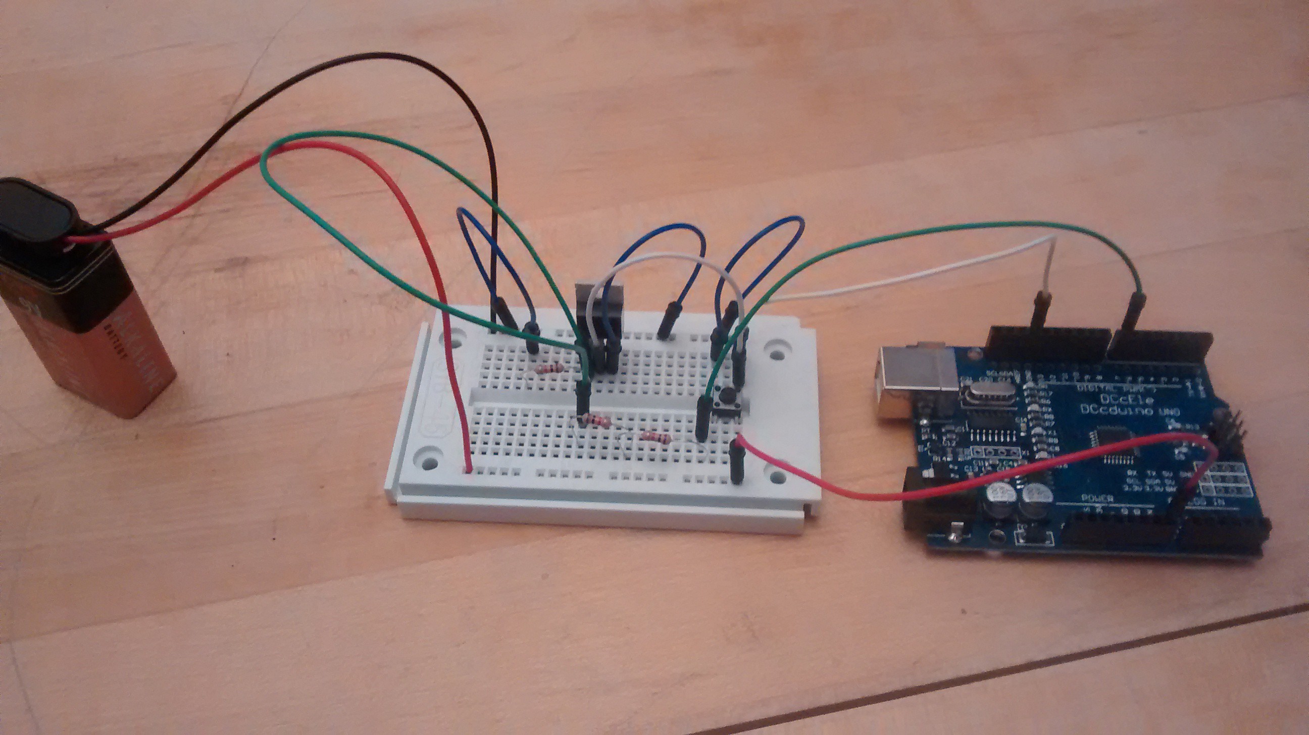
Here is a picture of the circuit when finished on the breadboard:
![]()
I am still missing the Trinket Pro, the accelerometer, and a better speaker.
-
Power circuit designed!
12/11/2014 at 04:28 • 0 commentsWhile I am waiting for my parts to arrive, I decided to work on designing the power circuit of the project.
A key part of the project is that you can hit a button to turn the board on, but hitting the button again does not turn it off. This is to prevent the thief from being able to turn the alarm off by simply hitting the on/off switch. I also wanted to have it so that the device would completely power off when not in use, not in a sleep mode or similar waiting for the arm button to be pressed.
I decided to make a circuit where the power from the battery would flow to the board by one of two ways:
1) a button
2) a transistor, which is controlled by digital pin on the microcontroller
The basic schematic is below: (the 7 is just because I used that pin when testing the circuit)
![]()
The transistor is an N-channel power MOSFET transistor, available here: https://www.adafruit.com/products/355?&main_page=product_info&products_id=355
Way over kill for this project, but it was what I had on hand. I imagine I can replace it with a ZVN2110A, which I can get from Mouser for less than a dollar. I anticipate relatively low current needs for this project, so that transistor should be able to handle it.
I also put in a 1k resistor to tie the gate of the MOSFET to ground (which was expected, and designed to keep that part of the transistor circuit normally off), but was not expecting to need to put in resistors between the digital pin on the microcontroller and the MOSFET gate. After some experimentation, I found that a resistor of between 1.7k and 2.2k did the trick. So I put in two 2k resistors when I constructed the circuit on the breadboard.
![]()
In the sketch, I have the digital pin that is tied to the MOSFET gate (in my case, pin 7) pulled to HIGH in the setup, so the MOSFET gate opens nearly as soon as the button is pressed. When the button is depressed, the MOSFET remains on and power continues to flow to the board. Further presses of the button have no impact. The circuit stays on until I decide to put the pin LOW, turning off the circuit completely and de-powering the board. In the test circuit, this occurred 5 seconds after the board turns on, but in the actual project I will program it to do so only when the correct 4-digit code has been punched in.
-
Components ordered!
12/08/2014 at 05:32 • 0 commentsI ordered the components that I am missing!
Ordered:
- 1x Trinket Pro from Hackaday.io (the screenprint looks badass)
- 1x MPU 6050 accelerometer
- A variety of small plastic boxes and project boxes from Amazon. I would like to put this in a small container, and eventually will try to 3D print this (but that will likely occur in the new year).
- Some nice, big momentary on buttons (5), also from Amazon
I have the LED, some other buttons should I need, the transistor etc. already. Just hoping the components don't take too long to arrive so I will be able to get down to working on the project.
TrinketPro Movement Alarm for Bag Theft Prevention
A portable, battery powered device that sounds an alarm when your bag is moved. Once armed, can only be turned off by your secret code.