 Ford Sleeman
-
1Step 1
Hardware
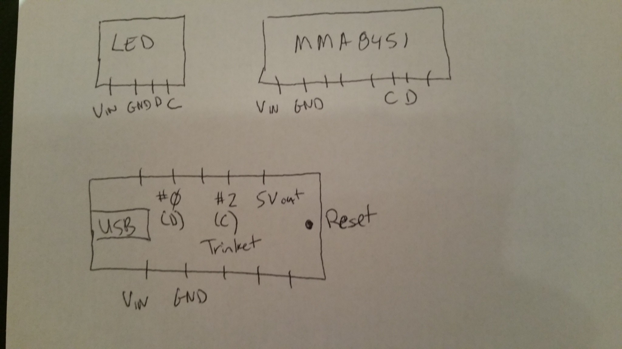
The assembly of components is pretty straightforward, although it would be easier with a proper PCB. Below is a diagram showing the pinouts of the three devices. They are all well marked although its not clear right off the bat which Trinket pins are used for clock (C) and data (D).
![]()
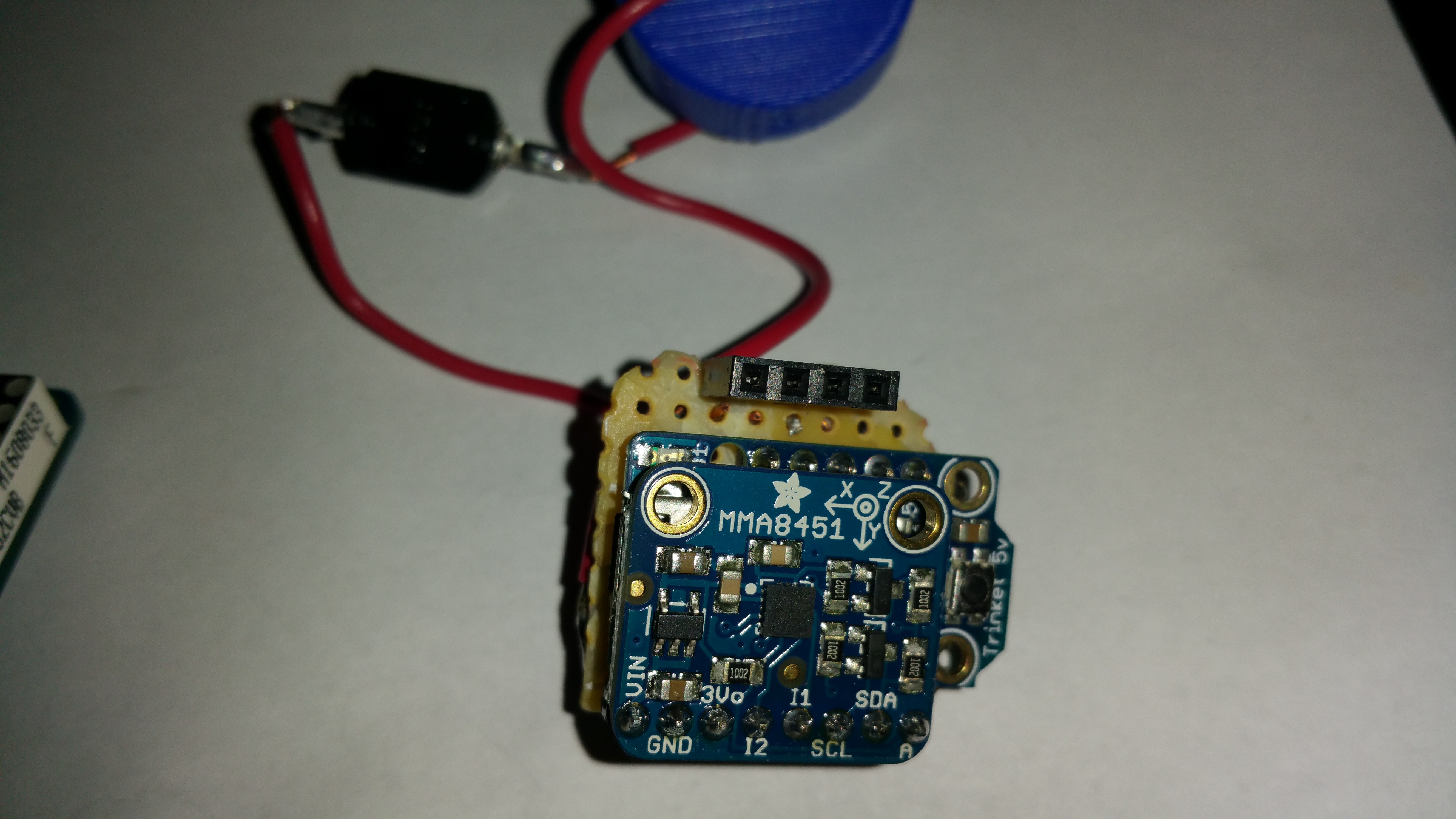
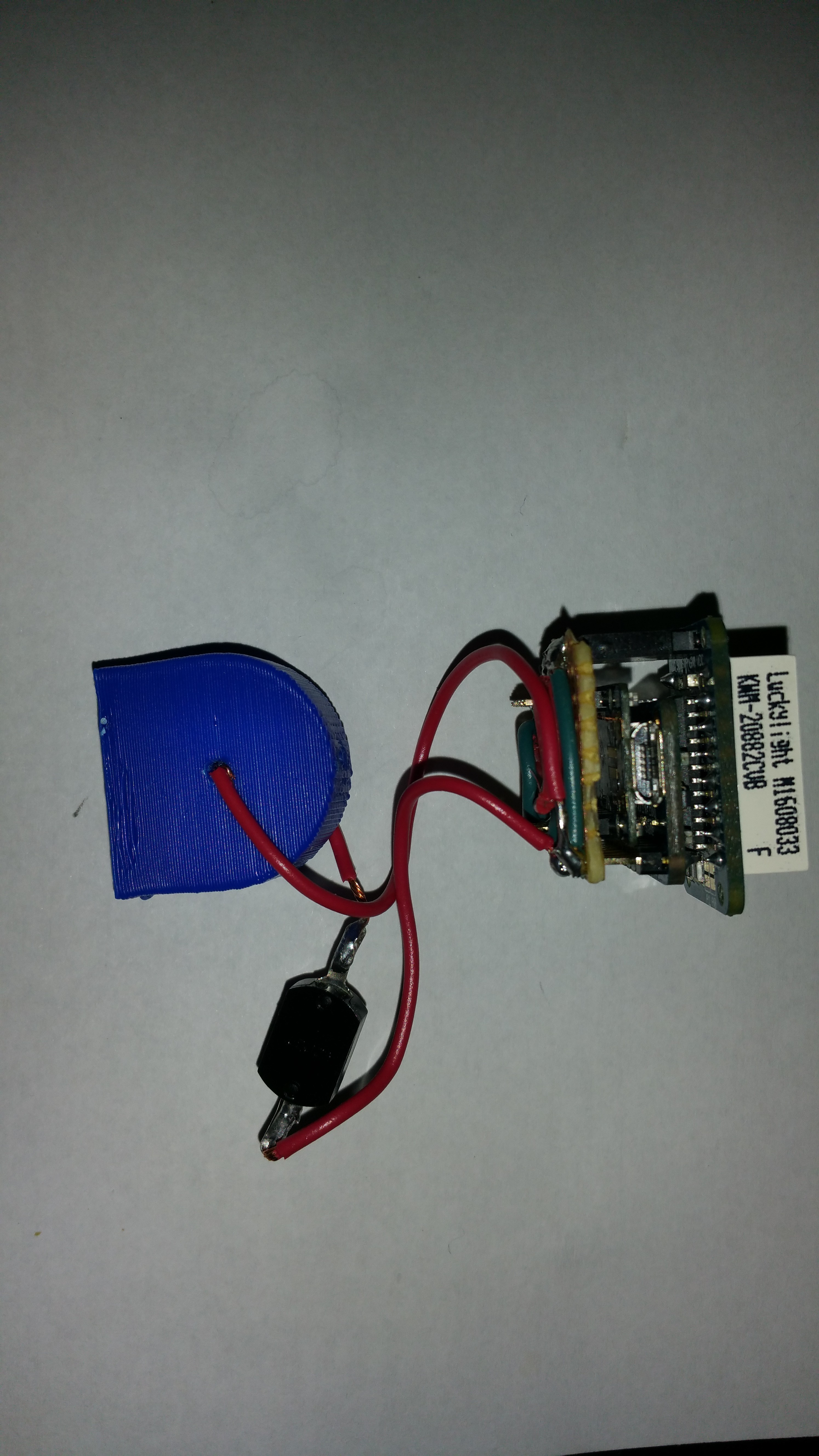
Below are some pictures of the assembled electronics.
![]()
![]()
My wiring is kind of a mess since I didn't have time to make a PCB but it worked. You can't tell very well from the picture above but the MMA8451 board fits nicely right over the Trinket board. The 4-pin female header was used to mount the LED matrix board.Once everything is wired, insert the LED matrix in the top portion of the enclosure. The battery holder has holes on each side to run in wires. With about 0.5 to 1.0 cm of wire on the inside, the batteries when inserted make a good contact with the wires. Then align the power button and then close both sides and finally, bolt the two sides together.
-
2Step 2
Software
In order for all of this code to fit under the 1k limit some of the interrupt code will need to be removed. The quickest and safest way to achieve this was to backup the Arduino code folder normally found in Windows under C:\Program Files (x86)\Arduino. With a backup copy it was safe to modify the code and still have a way to go back to the vanilla code.
The following modification in the Arduino core code needed to be made to fit the 1k limit:
(under C:\Program Files (x86)\Arduino\hardware\arduino\avr\cores\arduino)
In main.cpp comment line containing: init();.
This will disable a lot of interrupts not being used.
Accelerated Dice
A randomized dice using an Adafruit ATTINY85 breakout board, 8x8 LED matrix, and an accelerometer.
Discussions
Become a Hackaday.io Member
Create an account to leave a comment. Already have an account? Log In.